U.S. Pat. No. 7,131,907
SYSTEM AND METHOD FOR SUPERIMPOSING AN IMAGE ON ANOTHER IMAGE IN A VIDEO GAME
AssigneeKabushiki Kaisha Sega
Issue DateFebruary 21, 2002
Illustrative Figure
Abstract
An image processing device which places a display object within a virtually-defined three-dimensional space, creates a picture of the display object viewed from a virtual viewpoint with the image processing device, and displays the picture on a display. The image processing device comprises a display body setting element for setting a plurality of display bodies within said three-dimensional space; a display body disposal element for overlappingly disposing one of the plurality of display bodies within the display object, a display body image setting element for setting an image of the display object such that the one of the plurality of display bodies housed within the display object becomes visible, and a display body movement mode reflection element for making at least one movement mode of the one of the plurality of display bodies reflect a movement mode of the display object.
Description
DETAILED DESCRIPTION OF THE PREFERRED EMBODIMENTS FIG. 1shows a structure of the game device having the image display control in a 3D image according to the present invention programmed therein. InFIG. 1, the game device comprises a control unit1structured mainly with a CPU101and the like, an input device2for a player to input operational signals into the control unit1, an external storage device3storing an operating system (hereinafter referred to as “OS”) and application programs (game programs) and which inputs such programs in the control unit1when necessary, and an output device4structured of a display device4aand speaker4bamong others for providing images and sounds to the player. Further provided is a communication device5for transmitting and receiving data to and from other computers or game devices via a telephone line or the like. Without limitation to the CD-ROM or the like illustrated in the diagram, this may also be a recording medium capable of writing and retaining data from the control unit1. When the power is turned on to start the game, a boot program loader not shown loads the boot program (also referred to as an initial program) stored in the ROM102into the CPU101, and the CPU101executes this boot program. In accordance with this boot program, the CPU101loads all or the necessary portion of the OS stored in the CD-ROM or the like into the main memory103, and executes the OS. Under the control of this OS, the CPU101loads all or the necessary portion of the application program (hereinafter sometimes simply referred to as “program”) stored in the CD-ROM or the like into the main memory103, and, as required, loads the drawing data or image data stored in the CD-ROM or the like into the graphic memory104, and loads the sound data into the sound memory105. The CPU101executes the application program stored in the ...
DETAILED DESCRIPTION OF THE PREFERRED EMBODIMENTS
FIG. 1shows a structure of the game device having the image display control in a 3D image according to the present invention programmed therein. InFIG. 1, the game device comprises a control unit1structured mainly with a CPU101and the like, an input device2for a player to input operational signals into the control unit1, an external storage device3storing an operating system (hereinafter referred to as “OS”) and application programs (game programs) and which inputs such programs in the control unit1when necessary, and an output device4structured of a display device4aand speaker4bamong others for providing images and sounds to the player. Further provided is a communication device5for transmitting and receiving data to and from other computers or game devices via a telephone line or the like. Without limitation to the CD-ROM or the like illustrated in the diagram, this may also be a recording medium capable of writing and retaining data from the control unit1.
When the power is turned on to start the game, a boot program loader not shown loads the boot program (also referred to as an initial program) stored in the ROM102into the CPU101, and the CPU101executes this boot program. In accordance with this boot program, the CPU101loads all or the necessary portion of the OS stored in the CD-ROM or the like into the main memory103, and executes the OS.
Under the control of this OS, the CPU101loads all or the necessary portion of the application program (hereinafter sometimes simply referred to as “program”) stored in the CD-ROM or the like into the main memory103, and, as required, loads the drawing data or image data stored in the CD-ROM or the like into the graphic memory104, and loads the sound data into the sound memory105.
The CPU101executes the application program stored in the main memory104under the control of the OS. Data accompanying the execution of the application program is written in the main memory104and backup memory as necessary, and referred to thereby. The backup memory106stores data in order to retain the pending status of the game even if the power source is cutoff due to the discontinuance of the game.
Moreover, in the present embodiment, although the OS and application program and the like are structured to be provided from a CD-ROM, for example, these may be structured to be supplied from a ROM or another computer via a network.
A video display processor (VDP)107reads the drawing data necessary for displaying the image stored in the graphic memory104, performs various information processing (image processing) based on orders or data from the CPU101pursuant to the execution of the application program, and generates image data thereby. Various types of image processing are, for example, texture mapping, light source processing, display priority processing, and so on.
In order to display the generated image data on the display device4a, the VDP107outputs this to the encoder108. Further, the generated image data, for example, is written in the frame buffer memory or the like, and may be read in a prescribed timing from this frame buffer memory.
A sound processor109reads sound data stored in the sound memory105, and performs various information processing (sound processing) based on orders and data from the CPU101pursuant to the execution of the application program. Various types of sound processing are, for example, effects processing, mixing processing, and so on. Sound data to which various sound processing has been performed thereto is converted into analog data with the D/A converter110and output to the speaker.
A bus arbiter111performs control between the various units connected with the data transmission channel (via the bus9or the like). For example, in order to determine the unit to occupy the bus, the bus arbiter111determines the priority between the respective units and allocates a bus occupancy time for the occupying unit.
The game device of the present invention structured as described above realizes the prescribed functions according to the present invention by executing the program read by the CPU101from the external recording medium such as a CD-ROM or the like.
(Summary of Game Contents)
As shown inFIG. 2, the present game device displays a 3D image on the screen200, and such 3D image can be broadly classified into a background image202and an object image (hereinafter simply referred to as “object”)204which shifts and moves pursuant to the operation of the player.
The background image202corresponds to outer space, and the recreation room (room for playing “squash”) entirely surrounded by walls (8 faces) corresponds to a room capable of displaying various viewpoints. Now referring toFIG. 4, the wall206viewed from the outside is controlled to be transparent. In other words, when viewing the room three-dimensionally from the front, the front wall and the ceiling are transparent. Further, when viewing this room from the lower oblique direction (from below), the ceiling will become opaque, and the floor will thereby become transparent.
The content of this game is where an object204as the main character enters into this recreation room, counter-strokes the ball212bouncing back from all the walls by swinging the racket210(refer toFIG. 6) held by the object204, in order to destroy the plurality of blocks214provided to the rearmost wall206D.
(Characteristic Items in this Game Device)
(1) Text representing the start and end is sporadically displayed at the start and end of the game.(2) Displays of scores corresponding to the number of destroyed blocks and countdown of the time limit are displayed constantly during the game progress.(3) A life volume is provided for the object204, and the object204will not function if the game is not finished within a prescribed time. This life volume is displayed constantly.(4) The object204is capable of performing a special action (so-called finishing blows or secret moves) pursuant to the operation of the player in contrast to a standard action. The rate of reduction is set to become higher when implementing this special action.(5) An aura216is provided to the periphery of this object, and the object is displayed most conspicuously on the screen. Since this object204is in outer space, not only is it able to move freely across the floor and wall, it can also move along the left and right walls or the ceiling, and the image control is made so that the feet of the object204touches the nearest wall. An aura is image processing or image representation for making the object stand out from the background portion with fire, light or the like surrounding the object.(6) The movement (swinging of the racket210) of the object204is made to differ depending on the position of the approaching ball212.
Each of the foregoing paragraphs (1) to (6) is described in detail below.
((1) Sporadic Text Display Control)
As shown inFIG. 3(A), the display shows a state where fragments (218) are dispersed throughout the screen200. Here, since the situation is outer space, these fragments can be considered as stardust.
As shown inFIG. 3(B), each of such plurality of fragments218is structured of small polygons and provided with coordinates in advance, and gradually moves to the coordinate position of the ultimate position. Nevertheless, among the fragments218, some move to their coordinate positions at the shortest distance possible, whereas others move while creating a circular or spiral shape. Therefore, they do not arrive at their respective coordinate positions at the same time.
As shown inFIG. 3(C), the fragments218connect with each other at the determined position of each coordinate, and the aggregate218A thereof gradually forms some type of shape. Moreover, the fragments218which have not yet arrived at the coordinate position are floating around such shape.
As shown inFIG. 3(D), when all of the fragments218gather at a determined position of the coordinate position, they respectively form a text, and here, “GAME OVER” is displayed in a state it is recognizable by the player.
As described above, since stardust in the outer space gradually gathers, becomes connected, and forms an aggregate in order to represent a text, there is a sense of unity with the background image202, and the player will not feel a sense of displeasure when such text is to be displayed sporadically.
Next, the detailed description of the image processing relating to the fragments is explained below. The game device shown inFIG. 1executes the image processing described in paragraphs (1) to (6) above mainly by the CPU. The image processing means realized mainly by the CPU realizes the image processing to a three-dimensional image publicly known prior to the filing of the present application. In other words, the image processing means of the present invention is an image display control method which sets a three-dimensional spatial coordinate system and a three-dimensional viewpoint coordinate system for following the viewpoint movement, converts the coordinates of a first display body operated by a player belonging to the spatial coordinate system and a second display body other than the first display body belonging to the spatial coordinate system into the viewpoint coordinate system by employing a projection emitted from the viewpoint, and displays the display body disposed in a virtual three-dimensional space on a display screen.
The CPU loads necessary programs and data from a storage medium such as a CD-ROM storing game programs and game data into the main memory. And, with the support of the VDP and the like, the CPU foremost disposes the fragments in their initial positions. Next, the coordinate position of each fragment is read and stored in the main memory. Thereafter, the CPU reads the aggregate data table of the fragments among the data stored in the main memory, reads the final position of the fragments upon such fragments forming the aggregate, and stores this in a prescribed storage area of the main memory. The fragments are thereafter moved to their final positions.
The movement path of fragments is not particularly limited, and may be a preprogrammed path, the shortest linear distance sought from the current position of the fragments and the final position, and so on. The aggregate is a completed form of the image, text or the like upon executing the game. Text is information of letters or symbols significant in the game progress, and is the notification of game start or game over, game score, game time, and other explanations which are necessary during the game progress. One characteristic of the present embodiment is that the fragments which structure the aggregate—that is, the portion that forms the aggregate—is assimilated into the background image of the game. The fragments are assimilated as stardust into the background image of the outer space.
((2) Display Control of Constantly Displayed Text)
As shown inFIG. 4, text220requiring constant display (here, an example of the countdown display of the time limit is used) is displayed on the floor/wall in the background image202.
This text (number)220, as shown inFIG. 5, is structured of an aggregate of plate polygons222, which are a plurality of polygons. These polygons are disposed as a part of the object structuring the background. For example, the plate polygons are placed on the polygons structuring the background. Each of these plate polygons222is capable of being subject to gradation in accordance with the camera viewpoint, and, as a result, as shown inFIG. 4, is displayed in a three-dimensional state having concavities and convexities against the floor/wall206C. Here, the method of displaying the text is as follows. Models and textures from 0 to 9 are prepared as data in the ROM for drawing per frame. These texts are formed with polygons, and structured from a bottom face and side face. A texture having the same shape as the polygon is affixed to the bottom face (for example, “red” is attached, and textures graded in proportion to the superimposed polygons are attached to the polygons on the side face).
Moreover, these plate polygons222cannot become the counterstroke face of the ball212, and the floor/wall is judged as being planar. Next, the image processing in this case is described in detail. Gradation is semi-transparent processing, and an example of such gradation is to place the polygons On the background and perform gradation processing thereto, whereby the polygon color data and background color data are mixed in a prescribed ratio, and the polygons are colored lightly such that the player is able to see through such polygons to view the background in the rear. One reason for performing this type of processing is to assimilate the polygons into the background. When text such as points and remaining time are displayed in the background, there is a problem in that such text display stands out from the background. Thus, by performing gradation processing to the polygons structuring the text display, such text display becomes assimilated into the background.
In the foregoing embodiment, the floor area (background) to which the text display is placed and the angle formed with the virtual camera are calculated with the CPU. The virtual camera is placed in the vicinity of the main character, and moves in accordance with the movement of the main character. Gradation processing is performed when the camera angle is of a prescribed angle requiring such gradation processing, or when it is within a prescribed angle range. Pursuant to this gradation processing, the gradation of the area to be graded may be gradually changed.
((3) Establishment Place of Life Gauge)
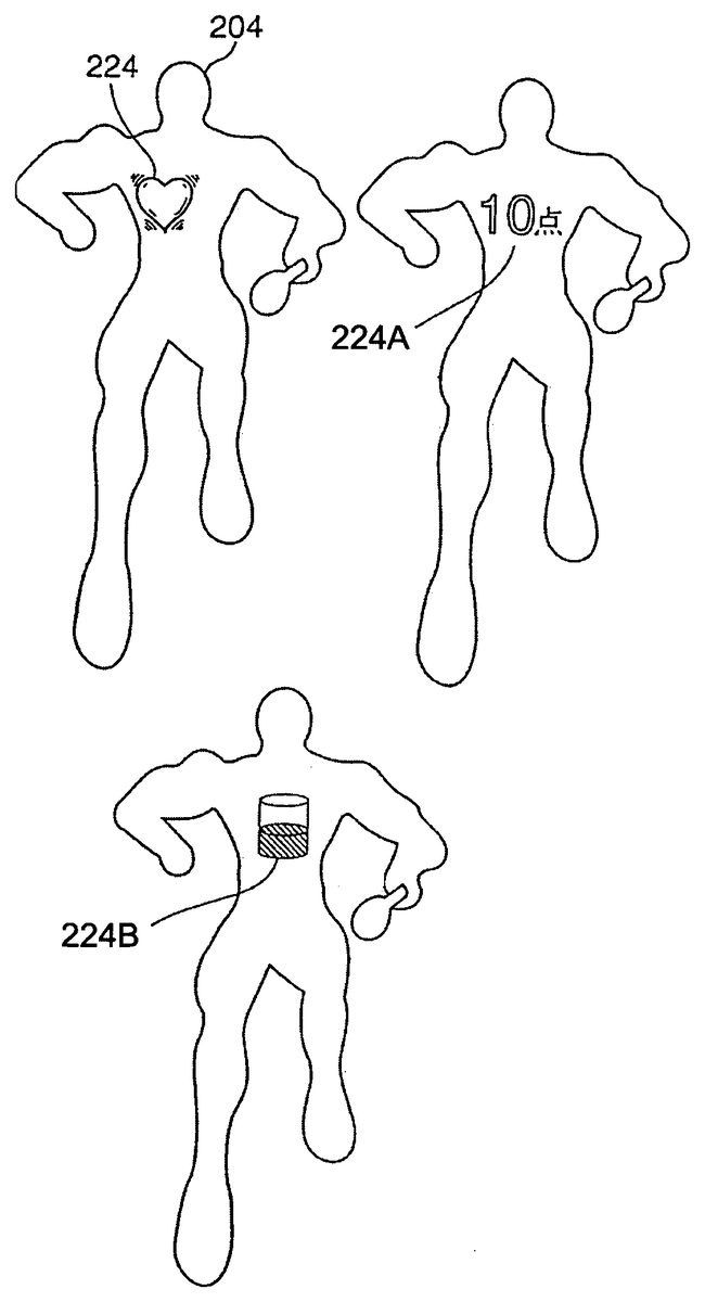
As shown inFIG. 6, the object204is basically transparent or semi-transparent, and only the contour thereof is displayed, and gradation is otherwise provided as necessary.
In the body of this object204near the heart, a heart-shaped life gauge224is displayed. The player is able to look through this. To summarize, this gauge corresponds to the display image reflecting the status in the game progress of the object processed in accordance with the instruction provided to the image processing device via the input device of the player. The aforementioned image processing means (CPU101) detects or calculates the status of the object, and reflects this in the form, shape or movement of the gauge. The gauge is displayed overlapping on the object. The gauge moves simultaneously with the movement of the object as a part of such object. Here, a gauge is a part of the display image representing information on the object. The display image includes, in addition to the foregoing life gauge, other types of various display information such as symbols, text and graphics representing the game score, countdown of the time limit and so on.
The exemplified life gauge224is constantly positioned at the heart of the object204, and, as a result, is controlled to move together with the movement of the object204. Further, the life gauge can be, in addition to the heart shape and as also illustrated inFIG. 6, that which a number224A, or it can be an indicator224B.
Further, since the life gauge224is also a 3D image, this is displayed with slightly differing shapes depending on the direction of the object204.
The scale of the life gauge224is represented by the speed of the contraction/expansion of the life gauge224itself. In other words, when the contraction/expansion of the life gauge224is slow, this implies that the heart is beating normally, and represents that sufficient life volume remains. Meanwhile, if the contraction/expansion of the life gauge224becomes fast, this is judged as an increased heartbeat, and represents that the life volume is beginning to decrease. For example, when the life volume becomes completely 0, the life gauge224may be destroyed.
Here, the number of objects to be displayed on the screen is not limited to one body, and a plurality of bodies may be displayed. In the latter case of a competition game, each player that becomes a participant in the competition game is able to operate an object, respectively. The foregoing display information can correspond to the game results of each object; that is, each player. The image processing device (CPU) of the game device can be made to be one of the opponents instead of a player. Since the display information representing the game result is displayed overlapping on the object, each player is able to instantly recognize the game result or game information of the object which he/she is operating. As a result, this is effective when a plurality of objects move around in the screen. The image processing means of the game device constantly monitors, calculates or determines the movement position of the object and overlaps such display information on this moving object in order to enable this processing. Here, if the display information is formed in a heart shape, the display information itself will become a part of the human organ, and the player will sense a prescribed reality.
Next, a modified example is described below. In other words, the CPU executes image processing of placing a second display body (life gauge) inside the first display body (object) such that the player is able to view the second display body through the first display body. Here, the second display body performs a rotational or oscillation movement, or periodic motion such as a reciprocating movement. This periodic motion varies depending on the motion property such as the movement speed of the first display body, or on the characteristics of the first display body. In other words, the periodic motion is controlled in correspondence with the game status of the character (parameters for determining the movement (status) of the character during the game progress such as the energy or physical strength of the character).
For example, when the motion speed of the first display body is fast, the periodic motion becomes fast. The CPU calculates the movement speed of the first display body. This calculation can be realized from the movement distance of the first display body and the number of frames required for such movement with respect to the movement speed of the display body. Further, the CPU may also read from the main memory the movement speed based on the series of motion data of the first display body.
((4) Movement Control of Special Action)
FIG. 7shows a functional block diagram for executing the movements of the special action and standard action.
The movement mode distinction unit226distinguishes whether a special action is being designated or a standard action is being designated based on the operational condition of the player, and sends the distinction result to the function selecting unit228.
At the function selecting unit228, a special action signal or a standard action signal is output based on the signal input from the movement mode distinction unit226.
A standard action signal is sent to the operational status determination unit230, and the operational status of the player of a standard action is determined, whereby such determination result is sent to the relative position control unit232. At the relative position control unit232, the relative position of the contact point of the racket210and the ball212is controlled as per the operation of the player, and sent to the processing execution unit234. At this processing execution unit234, images of the object204and the like are controlled based on the calculated movement.
Meanwhile, the special action signal in the function selecting unit228is sent to the lock-on setting unit236. The lock-on setting unit236commences the movement pursuant to the input of this special action signal, and locks on the relative position of the contact point position of the racket210and the ball212.
A lock-on is a movement where the ball212automatically follows the contact point of the racket210in accordance with the movement of the racket210.
The lock-on setting unit236is connected to the operational status determination unit238, and corrects the relative position of the contact point position of the racket210and the ball212by recognizing the player's operation and sending such operational status to the correction unit240. In other words, the correction unit240corrects the position of the contact point of the racket210and the ball212in a state with a reduced sense of unnaturalness on the image display, and the processing execution unit242controls images of the object204or the like based on the calculated (corrected) movement.
The movement control including the swing of the racket210of the object204is explained in accordance with the flowchart ofFIG. 8.
At step250, the operational status (standard or special) is determined, and, when determined as being a standard action, the routine proceeds to step252. The operational designation status by the player is thereby recognized, and, at the subsequent step254, the swing motion of the racket210is commenced based on such recognized operational designation.
Here, a standard movement is an ordinary motion provided to the character during the game progress, and, for example, is a frequently used command such as the walking, running or jumping of the character. These motions correspond to the button or pad on the controller. A special movement (particular movement) is a motion used less frequently, but aims at an extraordinary movement of the character in comparison to the standard movement. For instance, this would be the object counter-stroking the ball while performing a back flip, or returning the ball while running backwards, and so on. This special movement, for example, corresponds to the operation of a plurality of buttons, and, when there are three types of buttons A, B and C, this special movement occurs to the character when the A button and B button are pressed simultaneously. Moreover, during such special movement, since it is difficult for the player to counter-stroke the ball accurately while giving the character such special movement, the movement path or speed of the ball is adjusted, controlled or interpolated toward the racket.
Next, at step256, the relative positional relationship of the contact point of the racket210and the ball212is calculated, and at the subsequent step258, the counterstroke direction of the ball212is calculated based on such calculation result. The routine then proceeds to step260. At step260, the movement of the ball212is display controlled based on the result calculated at step258.
Here, there are cases where the ball212is hit toward an unexpected direction in accordance with the variance in the relative position of the contact point of the racket210and the ball212. When the ball is miss-hit, the ball212flies toward a direction different from the direction intended by the player. Thus, it is not possible to hit the block214accurately, and the subsequent counterstroke may become difficult.
Meanwhile, when a special action is determined at step250, the routine proceeds to step262in order to recognize the operational designation status of the player. Next, at step264, the swing motion is commenced, and, at the subsequent step266, the position of the ball212is corrected based on such recognized operational designation. The routine then proceeds to step256. In other words, the ball212is moved so as to follow the contact point position of the racket210.
Next, at the subsequent step256, the relative positional relationship of the contact point of the racket210and the ball212is calculated, and at the subsequent step258, the counterstroke direction of the ball212is calculated based on such calculation result. The routine then proceeds to step260. At step260, the display of the movement of the ball212is controlled based on the result calculated at step258.
Here, since the position of the ball212is corrected (made to follow) in accordance with the movement of the racket210, the ball212is counter-stroked accurately each time. It is thereby possible to hit the block214with accuracy.
As described above, in the case of a special action requiring difficult operations in comparison to a standard action, the player is able to concentrate on the operation of the special action by locking on the position of the contact point of the racket210and the ball212.
((5) Aura on the Object)
As shown inFIG. 9, a plurality of collision balls270are provided to the object204in advance.
The collision balls270are structured of a first collision ball270A provided at the waist position of the object and used as a reference; a second collision ball270B provided to the chest position of the object204; a third collision ball270C provided to the face position of the object204; fourth and fifth collision balls270D and270E provided to the upper arm portions of the object204; sixth and seventh collision balls270F and270G provided to the lower arm portions of the object204; eighth and ninth collision balls270H and270I provided to the wrist portions of the object204; tenth and eleventh collision balls270J and270K provided to the thigh portions of the object204; twelfth and thirteenth collision balls270L and270M provided to the knee portions of the object204; fourteenth and fifteenth collision balls270N and270O provided to the ankle portions of the object204; and sixteenth and seventeenth collision balls270P and270Q provided to the toes of the object204.
Here, although the camera viewpoint for displaying this object204is able to move freely in the three-dimensional space, a two-dimensional projection screen272(transparent) is always provided on the line connecting this viewpoint and the object204. The face of this projection screen (projection face)272is maintained perpendicular to the line connecting the viewpoint and the object204. This projection face is placed as close as possible to the camera viewpoint. Thus, the aura described later can constantly be displayed even when there is an obstacle existing between the object204and the camera viewpoint. The player will be able to recognize the existence (aura) of the object via the obstacle.
Here, as shown inFIG. 10, when displaying the object204with a prescribed camera viewpoint, a projection circle274of the collision balls270provided to the respective parts of the object204is formed on the projection screen272.
In this case, radial lines276divided into64segments are formed from the center of the first collision270A as the reference. In other words, each of the angles between the radial lines276is approximately 5°.
Here, the point (intersecting point X) farthest from the reference point in each of the radial lines276and the intersecting point with each collision270is sought, and, when connecting the adjacent intersecting points X adjacent to each other, the connected line will form a shape approximately coinciding with the contour of the object204.
In the present embodiment, a final contour point Y is set as the position in which a prescribed length a is extended on the radial lines276farther than the intersecting point X, and the area set by connecting the adjacent final contour points Y is made to be the aura generation area278.
Since a multiangular outermost contour will be formed when connecting the final contour points as is, correction processing is performed in order to correct such multiangles into a smooth curve (spline curve) by performing derivative processing to the adjacent final contour points.
This aura216may be displayed by using the radial lines276, or represented by performing gradation within the aura generation area178.
Next, the aura generation procedure is explained in accordance with the flowchart ofFIG. 11. At step300, it is judged whether it is an aura forming timing or not and, when the answer is judged as positive, the routine proceeds to step302in order to recognize the camera viewpoint. When this is judged as negative at step300, the routine proceeds to step304and advances to the subsequent step while omitting the aura display processing.
When the camera viewpoint is recognized at step302, the routine proceeds to step306in order to project the respective collisions270on the projection screen272. At the subsequent step308, the center of the projection circle274of the first collision270, which is the reference collision, is fixed.
At the subsequent step312, the intersecting point X of the farther most point in the intersecting point of the projection circle274of the aforementioned radial lines276and each collision270is calculated, and, at subsequent step314, a final contour point Y is set as the position in which a prescribed length α is extended on the radial lines276farther than the intersecting point X.
At the subsequent step316, the adjacent final contour points Y are connected in order to form the aura generation area. Here, the aforementioned correction processing is performed. At the subsequent step318, an aura is displayed on the aura generation area278, and this routine is thereby completed.
As described above, since the respective collisions270provided to the object204are projected on the projection screen272provided between such collisions and the camera viewpoint, numerous radial lines276(64in this example) are formed with the center of the projection circle274of the first collision270A as the reference, and the aura is formed thereby based on the projection circle274of each of the projected collisions270, it becomes possible to display an outer circle aura along the contour of the object204with approximate certainty no matter which direction the object204is facing. In this case, since calculation is performed with the two-dimensional projection circle projected on the projection screen272, the processing time and load are minimal and are sufficiently compatible with the movement of the game.
((6) Racket Swing Motion)
There are various swings of the racket; for instance, forehand stroke, backstroke, over throw, under throw, and so forth. Thus, the correlation of the object204position, the racket210position and the ball212position is prepared in a plurality of conditions in advance in the likes of an LUT, and the optimum swing mode is read on a case-by-case basis pursuant to the position of the approaching ball212in order to realize a realistic movement by setting the automatic movements of the object (swinging of the racket210) to be different.
Another embodiment of the present invention is now explained. This embodiment is a modified example of the foregoing example ofFIG. 6. With the embodiment ofFIG. 6, a life gauge is housed in a transparent character, and the movement status (rotational speed of the heart-shaped life gauge) is made to change in accordance with the movement status of the character (a state of the character possessing much game life or a state of the character possessing little game life). In the embodiment described later, a monkey-shaped character in a transparent spherical body (ball) shows a behavior toward the moving direction of the ball.
This embodiment is structured and operated as follows.FIG. 12andFIG. 13are representative game screens relating to the present embodiment. A game screen based on various data including data obtained by the CPU or VDP described inFIG. 1pursuant to the operation of the controller pad by the player or a game program is displayed on the monitor.
The game content is where a character502(second display body) simulating a monkey enters a transparent ball500(first display body), and both the ball and monkey (synthesized display body) aim for the goal by the ball rolling along a determined path. In comparison toFIG. 6, the first display body is the object, and the second display body corresponds to the display information. During the course of the ball arriving at the goal, the character scores game points if the character is in the vicinity of a banana506, which is a source of points. Game points correspond to the numerical value displayed as SCORE.
The game progresses pursuant to the operation of a game application against the image data structured from three-dimensional coordinate data with a well-known method. The character rolls on a rectangular plate face503floating in the air. By moving the operation lever (control pad) provided in the front of the industry-use game device body, the player is able to decide the inclination direction of the plate503in the air. Gravity is defined in the virtual space referred to as the game space. Thus, the ball will roll on the plate face inclined toward the gravitational direction.
The front of the character in the ball is made to face the direction in which the ball is rolling.FIG. 12shows that the ball is rolling in an upper-left oblique direction in the diagram, andFIG. 13shows that the ball is rolling toward the backside in the diagram.
In either case, the front of the character in the ball is facing the direction in which the ball is rolling. In order for the game device to recognize the front of the character, the front of the character is defined with a vector. By the processing means of the CPU or VDP recognizing the rolling direction of the ball, the front of the character can be aligned with the rolling direction of the ball.
In order to enable the player to recognize the character in the ball, the ball is an empty or solid spherical body, and the color data thereof is transparent data or data corresponding to a hypochromic color in which the inside can be observed. The ball may also be displayed semi-transparently, or processing may be performed so as to alternately thin out the pixels. Further, in order to make the player recognize the contour of the ball, a line is provided to the area of the ball. Thus, this is also a display body in which only the contour of the display body corresponding to the ball is displayed. As described above, the player is able to determine the rolling direction of the ball (direction in which the plate is inclined) by the direction (front direction of the character) to which the character inside the ball is facing.
When the ball is rolling along a straight line, a scene of the character inside the ball strolling along is provided to the player. When the ball is being prevented from falling off the plate, a representation of a behavior where the character inside the ball is on its hands and knees showing resistance or haste in order to keep the ball from falling is adopted in the game machine. Since the area outside the plate is set as a space where gravity exists in the real world, if the ball falls off the plate, the ball drops toward the bottom of the screen.
The processing means (CPU, VDP) of the image processing device of the game machine described inFIG. 1exhibits the functions described with the following functional blocks in order to realize the foregoing movements. Please refer toFIG. 14.
When the game is started with the game start means, the game is executed based on the player's input orders of the input means. The game execution means comprises plate face inclination means; rolling means for rolling the ball in the gravitational direction on the inclined plate face; orientation direction for detecting the rolling direction of the ball and making the front of the character face such direction; ball rolling status detection means for detecting the rolling status of the ball (rolling in a straight line, rolling in a curve, the ball swaying and rolling as though about to fall off the plate face, and so on); and means for selecting the movement of the character matching the rolling status of the ball (mode of the character strolling along when the ball is rolling in a straight line, mode of the character in a haste when the ball is about to fall off, and so on), and the image processing means comprises means for judging whether the game is over.
This is now explained in detail based on the flowchart ofFIG. 15. When the game is started, the image processing means reads the image data and application software in the memory, and realizes the aforementioned game processing based on this program, image data, and the data input from the input means of the game device (1500).
Foremost, when the game is started, the course is displayed on the screen. Next, the character inside the ball is disposed at the starting point of the course. A prescribed time limit is provided. The operational signal from the operation means operated by the player is read. The plate face structuring the course is inclined toward a prescribed direction based on the operational signal (1502). The ball is rolled in this direction.
The character is displayed to match the mode of the rolling of the ball. The character behavior described above arises during the process of such processing (1504). In other words, a behavior of the character that is strolling along or flapping its hands and feet so as to resist falling from the course, is adopted.
Next, the rolling direction of the ball is detected, and the front direction of the character is set to this direction (1506). Then, the collision of the ball and plate surface, i.e., whether there is an overlap or contact of coordinates, is determined. When there is a contact, the ball has not fallen from the plate face and it is still on the plate face. When the ball is not on the plate face, the ball is made to drop from the course (1508).
Then, it is decided whether it is within the time limit, and the ball is mandatorily returned to the starting point when exceeding the time limit. As a modified example, the ball may be returned to the starting point of the previous stage. When within the time limit, it is determined whether the goal has been reached, and the game proceeds to the subsequent stage when the goal has been reached. Thereafter, it is judged whether it is game over or not, and the game over is judged in accordance with the game results.
In this embodiment, the aforementioned collision determination is implemented between the ball (spherical body) and the plate face. Since the spherical body is defined pursuant to a certain radius from the center point thereof, the collision determination of the floor area and the spherical body can be calculated simply. By housing a monkey, which cannot be approximated with a simple shape, in the spherical body, only the collision between the spherical body (subject of collision determination) and the floor area (other subject of collision determination) needs to be determined, and the determination result is accurate.
Moreover, since the player is able to see through to the character (second display body) in the ball (first display body), the player is able to recognize the character inside of the ball from every direction. Although the front of the character (monkey) inside the ball was made to face the moving direction of the ball, the behavior or form of the monkey-shaped character may be modified or adjusted in correspondence with the movement of the ball. As a modified example of the above, the following example may be adopted. The behavior of the monkey may be changed in accordance with the speed of the ball. Or, the display body on the outside may be changed in accordance with the movement of the monkey.
Further, in this embodiment also, a plurality of synthesized display bodies may be provided for each participating player. In addition, information of the game result or the like may be overlapped on the first display body and/or second display body as the third display body.
Effect of the Invention
The image display control method in a 3D image and the device thereof, as well as a recording medium and game device having recorded thereon such image display control method according to the present as described above yield a superior effect enabling the player to maintain the virtual feeling in the game without losing the balance of the image by displaying text or the like as though a telop on the screen, and preventing the deterioration in game amusement by yielding a sense of unity with the game screen even in a sporadic text display.
Moreover, in addition to the foregoing effect, two or more types of information are obtained upon suppressing the shifting of the player's viewpoint as much as possible.
Further, when complex operations are necessary by the player, he/she may concentrate on such complex operation by the other elements, which ordinarily require consideration, being simplified.
In addition, upon generating an aura, which is a means for reinforcing an object of a main character class, only a simple image processing is required to match the aura with the contour of such object and accommodate even complex movements.
Claims
- An image processing device which places display bodies within a virtually-defined three-dimensional space, creates a picture of the display bodies viewed from a virtual viewpoint with image processing means, and displays the picture on display means, said image processing means comprising: display body setting means for setting a plurality of display bodies within said three-dimensional space;display body disposal means for overlappingly disposing within a first of the plurality of display bodies, a second of the plurality of display bodies;display body image setting means for setting an image of the first of the plurality of display bodies such that the second of the plurality of display bodies becomes visible;and display body movement mode reflection means for making at least one movement mode of the one of the first of the plurality of display bodies reflect a movement mode of the second of the plurality of display bodies, wherein the second of the plurality of display bodies is displayed in differing shapes depending on the movement mode of the one of the first of the plurality of display bodies.
- An image processing device according to claim 1 , wherein the first of the plurality of display bodies is transparent and the second of the plurality of display bodies is opaque.
- The image processing device according to claim 1 or claim 2 , wherein said display body movement mode reflection means comprises: display body movement detection means for detecting a movement of one of the first or the second of the plurality of display bodies;and movement adjustment means for creating a movement matching the detected movement in the other of the first or second of the plurality of display bodies.
- The image processing device according to claim 3 , wherein: said display body movement detection means comprises display body moving direction detection means for detecting a moving direction of one of the first or second display bodies, and said movement adjustment means comprises means for creating an orientation or a moving direction of the other of the first or the second of the plurality of display bodies.
- An image processing device according to claim 1 , wherein periodic motion associated with the second of the plurality of display bodies varies depending on movement speed of the one of the first of the plurality of display bodies.
- An image processing device according to claim 1 , wherein behavior associated with the second of the plurality of display bodies varies depending on the movement mode of the one of the first of the plurality of display bodies.
- A game device comprising an image processing device which places display bodies within a virtually-defined three-dimensional space, creates a picture of the display bodies viewed from a virtual viewpoint with image processing means, and displays the picture on display means, said image processing device comprising: display body setting means for setting a plurality of display bodies within said three-dimensional space;display body disposal means for overlappingly disposing within a first of the plurality of display bodies, a second of the plurality of display bodies;display body image setting means for setting an image of the first of the plurality of display bodies such that the second of the plurality of display bodies becomes visible;and display body movement mode reflection means for making at least one movement mode of the one of the first of the plurality of display bodies reflect a movement mode of the second of the plurality of display bodies, wherein the second of the plurality of display bodies is displayed in differing shapes depending on the movement mode of the one of the first of the plurality of display bodies.
- A computer program product employed in an image processing device which places a display body within a virtually-defined three-dimensional space, creates a picture of the display body viewed from a virtual viewpoint with image processing means, and displays the picture on display means, said computer program product storing instructions for execution by a computer to: set a plurality of display bodies;overlappingly dispose within a first of the plurality of the display bodies, a second of the plurality of display bodies;set an image of the first of the plurality of display bodies such that the second of the plurality of display bodies becomes visible;and make at least one movement mode of the first of the plurality of display bodies reflect a movement mode of the second of the plurality of display bodies, wherein the second of the plurality of display bodies is displayed in differing shapes depending on the movement mode of the one of the first of the plurality of display bodies.
- A storage medium storing a program employed in an image processing device which places a display body within a virtually-defined three-dimensional space, creates a picture of the display body viewed from a virtual viewpoint with image processing means, and displays the picture on display means, said program instructing a computer to: set a plurality of display bodies;overlappingly dispose within a first of the plurality of the display bodies, a second of the plurality of display bodies;set an image of the first of the plurality of the display bodies such that the second of the plurality of display bodies becomes visible;and make at least one movement mode of the first of the plurality of display bodies reflect a movement mode of the second of the plurality of the display bodies, wherein the second of the plurality of display bodies is displayed in differing shapes depending on the movement mode of the one of the first of the plurality of display bodies.
Disclaimer: Data collected from the USPTO and may be malformed, incomplete, and/or otherwise inaccurate.