U.S. Pat. No. 7,118,480
METHOD, APPARATUS, STORAGE MEDIUM AND PROGRAM FOR GENERATING IMAGE DATA OF VIRTUAL SPACE
AssigneeBandai Namco Entertainment Inc
Issue DateJuly 24, 2002
Illustrative Figure
Abstract
A method for generating image data of a virtual space viewed from a predetermined view point, comprises: determining a boundary of a predetermined plane area in the virtual space; providing a line object having one boundary line portion which is at least one portion of the boundary and a predetermined width in a direction of an inside of the plane area; and changing the width of the line object with fixing the one boundary line portion.
Description
PREFERRED EMBODIMENTS OF THE INVENTION Hereinafter, a preferred embodiment of the present invention will be explained with reference to figures, in detail. Further, hereinafter, although the present invention will be explained in case the present invention is applied to, for example, a tennis game, it should be understood that the present invention is not limited to the case. First, a principle of the present invention will be explained. In the tennis game to which the present invention is applied, as shown inFIG. 1, a tennis court10and a virtual camera20are provided in a game space. Herein, the game space means a virtual three dimensional space represented by the world coordinate system, that is, the XYZ rectangular coordinate system. Further, in the following explanation, coordinates values are represented by the world coordinate system while it is not limited specially. FIG. 1is a view showing an example of the game space of the tennis game. As shown inFIG. 1, the tennis court10is provided in the X-Z plane of the game space so that a longitudinal direction (a right and left direction inFIG. 1) of the tennis court10coincides with the X-axis direction of the game space, a width direction (a far direction inFIG. 1) of the tennis court10coincides with the Z-axis direction of the game space, and a height direction of the tennis court10coincides with the Y-axis direction of the game space. A plurality of player objects, a ball object and so on, which are not shown in figures are provided in the tennis court10. Therefore, when a player or a computer instructs and controls a movement of the player object or the like, the tennis came is advanced. The virtual camera20has a fixation point F at a center position of the tennis court10, and is provided at a position wherein the almost whole ...
PREFERRED EMBODIMENTS OF THE INVENTION
Hereinafter, a preferred embodiment of the present invention will be explained with reference to figures, in detail. Further, hereinafter, although the present invention will be explained in case the present invention is applied to, for example, a tennis game, it should be understood that the present invention is not limited to the case.
First, a principle of the present invention will be explained.
In the tennis game to which the present invention is applied, as shown inFIG. 1, a tennis court10and a virtual camera20are provided in a game space.
Herein, the game space means a virtual three dimensional space represented by the world coordinate system, that is, the XYZ rectangular coordinate system. Further, in the following explanation, coordinates values are represented by the world coordinate system while it is not limited specially.
FIG. 1is a view showing an example of the game space of the tennis game.
As shown inFIG. 1, the tennis court10is provided in the X-Z plane of the game space so that a longitudinal direction (a right and left direction inFIG. 1) of the tennis court10coincides with the X-axis direction of the game space, a width direction (a far direction inFIG. 1) of the tennis court10coincides with the Z-axis direction of the game space, and a height direction of the tennis court10coincides with the Y-axis direction of the game space.
A plurality of player objects, a ball object and so on, which are not shown in figures are provided in the tennis court10. Therefore, when a player or a computer instructs and controls a movement of the player object or the like, the tennis came is advanced.
The virtual camera20has a fixation point F at a center position of the tennis court10, and is provided at a position wherein the almost whole tennis court10comes into sight of the virtual camera20. The initial position of the virtual camera20is C (cx, cy, cz).
The state of the game space, viewed from the virtual camera20is displayed on a display or the like of a game apparatus, as the game image.
The tennis court10consists of a plurality of lines, by combining them, as shown inFIG. 2.
FIG. 2is a plan view showing a state wherein the tennis court10is viewed from the Y-axis direction.
As shown inFIG. 2, the tennis court10consists of nine lines in total, including two base lines, two doubles sidelines and so on.
Each of the nine lines is represented by corresponding one polygon. Hereinafter, nine polygons corresponding to the nine lines respectively will be called line polygons1to9. That is, when nine line polygons1to9are combined and provided in the game space, the tennis court10lined with nine line polygons1to9is formed in the game space, as shown inFIG. 1.
Each of the line polygons1to9is a polygon formed in a rectangle, and has a length and a width shown inFIG. 3.
FIG. 3is a table showing an example of the length and the width of each of line polygons1to9.
As shown inFIG. 3, the length of each of the line polygons1and2is “L1” equally. The “L1” is equal to the length of the width direction of the tennis court10. The length of each of the line polygons3,4,7and8is “L2” equally. The “L2” is equal to the length of the longitudinal direction of the tennis court10. The length of each of the line polygons5and6is “L3” equally. The length of the line polygon9is “L4”.
On the other hand, the width of each of the line polygons1to9is “W” equally.
FIG. 4is a view showing an example of the line polygon1.
As shown inFIG. 4, the line polygon1has coordinates values, fixed flags and moving directions for four vertexes P1to P4respectively.
The fixed flag indicates whether the vertex having the fixed flag can move or not More specifically, the fixed flag is determined to be “OFF” when the vertex can move, and to be “ON” when the vertex cannot move.
Herein, to move the vertex means to change coordinates values of the vertex, and further, hereinafter, it means so. That is, when the coordinates values of the vertex is changed, the vertex is moved.
The moving direction indicates the direction in which the vertex is moved when the vertex can move, that is, when the fixed flag is “OFF”. More specifically, the moving direction is determined to be “+x” or “−x” to move the vertex in the direction along the X-axis, and to be “+z” or “−z” to move the vertex in the direction along the Z-axis. The sign (+, −) indicates the direction in which the vertex is moved, in order to increase the width W of the line polygon.
For example, when the moving direction is “+x”, in order to increase the width W, the vertex is moved in the positive direction along the X-axis. On the other hand, when the moving direction is “−x”, the vertex is moved in the negative direction along the X-axis.
When the fixed flag is “ON”, that is, when the vertex cannot move, the moving direction of the vertex is not determined specially, and represented by “*”.
As shown inFIG. 4, regarding the vertex P1, the coordinates values are (x1, y1(=0), z1). The fixed flag is “ON”. The moving direction is not determined specially, and represented by “*”.
Regarding the vertex P2, the coordinates values are (x2, y2(=0), z2) The fixed flag is “ON”, as well as the vertex P1. The moving direction is not determined specially, and represented by “*”.
Regarding the vertex P3, the coordinates values are (x3, y3(=0), z3). The fixed flag is “OFF”. The moving direction is determined to be “+x”.
Regarding the vertex P4, the coordinates values are (x4, y4(=0), z4). The fixed flag is “OFF”, as well as the vertex P3. The moving direction is determined to be “+x”.
That is, in the line polygon1, only the vertexes P3and P4can move among four vertexes P1to P4. Therefore, as the vertexes P3and P4is moved in the positive direction along the X-axis, the width W of the line polygon1increases. Further, when the vertexes P3and P4are moved, only the width W of the line polygon1is changed, and the length L1of the line polygon1is not changed specially.
FIG. 5is a view showing an example of the line polygon9.
As shown inFIG. 5, the line polygon9has four vertexes P1to P4. Regarding each of the four vertexes P1and P4, the fixed flag is “OFF. Regarding each of the vertexes P1and P2, the moving direction is “+z”, and regarding each of the vertexes P3and P4, the moving direction is “−z”.
That is, in the line polygon9, all the vertexes P1to P4can move. Therefore, as the vertexes P1and P2are moved in the positive direction along the Z-axis, and the vertexes P3and P4are moved in the negative direction along the Z-axis, the width W of the line polygon9increases. Further, when the vertexes P1to P4are moved, like the line polygon1, only the width W of the line polygon9is changed, and the length L4of the line polygon9is not changed specially.
Although the line polygons2to8are not explained specially, in detail, each of them has the structure like the above-described line polygon1or9. In each of the line polygons2to8, coordinates values, fixed flags and moving directions are determined for four vertexes P1to P4, respectively.
Herein, it will be explained how to determine the fixed flag and the moving direction for each of the line polygons1to9.
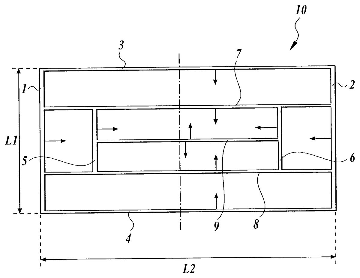
FIG. 6is a view for explaining the direction in which the width W of each of the line polygons1to9is changed.
As shown inFIG. 6, the line polygons1to9are changed in the arrow directions attached thereto respectively, so that the width Ws of the line polygons1to9increase. Therefore, because the width Ws of the line polygons1to9are changed according to the rule of tennis, it is possible to prevent the size (area) of the tennis court10from being changed carelessly.
That is, according to the rule of tennis, on the line is determined to be inside of the tennis court10(IN). Therefore, there is a case wherein a wrong condition occurs that the area determined to be inside of the tennis court10is changed by changing the widths Ws of the line polygons and the progress of the tennis game is affected thereby. Accordingly, in order to prevent the wrong condition from occurring, the line polygons1to9have the fixed flags and the moving directions respectively, so that the width Ws thereof are changed in the direction of the inside of the tennis court10.
Further, for the above-described reason, the length L1to L4of the line polygons1to9are not changed.
For example, the line polygon1is changed so that the width W thereof increases in the right direction inFIG. 6. That is, as shown inFIG. 4, the line polygon1is changed so that the vertexes P1and P2are fixed and the vertexes P3and P4are moved in the positive direction along the X-axis.
Further, the line polygon9is changed so that the width W thereof increases in the upper direction and the lower direction inFIG. 6. That is, as shown inFIG. 5, the line polygon9is changed so that the vertexes P1and P2are moved in the positive direction along the Z-axis, and the vertexes P3and P4are moved in the negative direction along the Z-axis, in other words, so that all the vertexes P1to P4are moved along the Z-axis.
As described above, moving the vertexes of the line polygons1to9, that is, changing the width Ws of the line polygons1to9, is performed on the basis of the position of the virtual camera20. Next, the relationship between changing the width of the line polygon and the position of the virtual camera20will be explained, as follows.
FIG. 7is a view showing an example of the line polygon after the line polygon1shown inFIG. 4is changed.
As shown inFIG. 7, in the changed line polygon1, the vertex P3is moved to the vertex P3′, and the vertex P4is moved to the vertex P4′ Herein, the moving direction of each of the vertexes P3and P4is the positive direction along the X-axis, that is, the right direction inFIG. 7, as explained with reference to figures.
Further, the coordinates values of the vertex P3′ are (x3+ΔW, y3, z3), and the coordinates values of the vertex P4′ is (x4+ΔW, y4, z4).
That is, after the vertexes P3and P4are moved to the vertexes P3′ and P4′, the width of the line polygon1increases by ΔW, to be “W+ΔW”. Herein, the change ΔW is larger than 0 (ΔW>0).
The length of the line polygon1is not changed, and keeps L1.
The change ΔW by which the width W of the line polygon1increases is determined on the basis of the position of the virtual camera20, and in detail, on the basis of the change Δy of the height h of the virtual camera20from the X-Z plane. Rough speaking, as the height h of the virtual camera20lowers, the width W of the line polygon1increases. Herein, the height h of the virtual camera20is equal to the Y-coordinates values of the virtual camera20.
FIG. 8is a view for explaining the change of the position of the virtual camera20.
As shown inFIG. 8, the position of the virtual camera20changes from C(cx, cy, cz) as the initial position to C1(cx, cy−Δy, cz). That is, the height h of the virtual camera20lowers from “cy” to “cy−Δy”, by “Δy”. Herein, the change Δy is larger than 0 (Δy>0).
When the height h of the virtual camera20changes, because the fixation point F is fixed, the eyes direction (eyes vector) also changes according to the change of the position of the virtual camera20.
Therefore, the vertexes of the line polygon1is moved so that the width W of the line polygon1increases by ΔW (>0) according to the change Δy of the height h of the virtual camera20.
The vertexes having the fixed flags “OFF” are moved, as explained with reference to figures.
The change ΔW of the width W of the line polygon is obtained by the following equation (1).
ΔW=f(Δy) (1)
According to the equation (1), the change ΔW of the width W of the line polygon1is represented by the function “f” with the change Δy of the height h of the virtual camera20, as a parameter.
The function “f” may be any function. However, in order to represent the phenomenon wherein the width W of the line polygon1increases (widens) as the height h of the virtual camera20lowers, the function “f” may preferably be determined so that the change ΔW increases as the change Δy increases.
Therefore, the function “f” shown inFIG. 9is adopted as the above-described function “f”.
FIG. 9is a graph showing an example of the relationship function between the change Δy and the change ΔW.
According to theFIG. 9, the equation (1) is the following equation (2).
ΔW={0(Δy≦0)A×Δy(0<Δy<ya)Wa(ya≦Δy)(2)
Herein, “A” is a constant.
That is, the change ΔW is equal to “A×Δy” (ΔW=A×Δy), within the change Δy is larger than “0” and smaller than “ya” (0<Δy<ya). Further, the change ΔW is equal to “0” (ΔW=0), within the change Δy is equal to or smaller than “0” (Δy≦0). Further, the change ΔW is equal to “Wa” (ΔW=Wa), within the change Δy is equal to or larger than “ya” (ya≦Δy).
As shown in the equation (2), the change ΔW of the width W has the upper limitation Wa. Therefore, it is possible to prevent the ratio of the line to the whole tennis court10from increasing too much according as the width W of the line polygon increases, and the line from giving an unnatural impression to the display image.
As described above, each vertex, and in detail, each of the vertexes P3and P4of the line polygon1are moved so that the width W of the line polygon1increases by only the change ΔW according to the change Δy from the initial position C, of the height h of the virtual camera20.
Further, regarding each of the line polygons2to9, like the line polygon1, each of the vertexes P1to P4is moved by only the change ΔW in the moving direction, according to the change Δy from the initial position C, of the height h of the virtual camera20. That is, each of the vertexes P1to P4of each of the line polygons1to9is changed, so that the width W of each of all the line polygons1to9increases by only the same change ΔW according to the change of the position of the virtual camera20.
As described above, the first case has been mainly explained to increase the width W of each of the line polygons1to9. However, the second case of reducing the width W is like the first case.
In the second case, the direction in which each of the vertexes P1to P4is moved is opposite to the direction in which each of the vertexes P1to P4is moved in the first case. For example, when the moving direction is determined to be “+x” in the first case, the moving direction is determined to be the negative direction along the X-axis in the second case.
FIG. 10is a block diagram showing an example of a functional block of a game apparatus100to which the present invention is applied.
As shown inFIG. 10, the functional block of the game apparatus100, comprises an input unit200, a display unit300, a processing unit400, a storage unit500and a temporary storage unit600.
The input unit200is used by a player for inputting an operation data. The input unit200has a function which can be realized by hardware such as a lever, buttons, a covering body or the like. When the player operates the input unit200, for example, when the player pushes any of the buttons or the like, the input unit200outputs the operation signal to the processing unit400.
The display unit300displays the game image or the like generated by an image generation unit420of the processing unit400, thereon. Therefore, the player inputs the operation data according to the progress of the game with the input unit200, with watching the game screen displayed on the display unit300.
The processing unit400performs various processing including the control over the whole game apparatus100, the instruction to each unit of the game apparatus100, the game progress processing, the image processing, the sound processing, and so on. The processing unit400has a function which can be realized by hardware such as various types processors (CPU(Central Processing Unit), DSP(Digital Signal Processor) or the like), an ASIC(Application Specific Integrated Circuit) or the like, or predetermined program.
Further, the processing unit400comprises a game operation unit410and an image generation unit420.
The game operation unit410performs the processing of forming the game space, the processing of calculating the position, the posture, the moving speed, the moving direction or the like, of each character, the processing of operating the position or the eyes direction of the virtual camera20in the game space, the progress processing in the game such as a story development, or various game processing, on the basis of the operation signal outputted from the input unit200, the game program read out of the storage unit500or the like.
For example, the game operation unit410provides the line polygons1to9and forms the tennis court10in the game space, as shown inFIG. 1, on the basis of a changed line polygon data610stored in the temporary storage unit600.
Further, the game operation unit410comprises a virtual camera determination unit411and a vertex coordinates change unit412.
The virtual camera determination unit411provides the virtual camera20at the initial position C which is previously determined, in the game space. When the virtual camera determination unit411receives the instruction to change the position, the eyes direction or the like of the virtual camera20, the virtual camera determination unit411changes the position at which the virtual camera20is provided, or the like according to the instruction. Further, the virtual camera determination unit411performs the processing of adjusting the eyes direction (eyes vector) without changing the fixation point F, with changing the position at which the virtual camera20is provided.
The vertex coordinates change unit412performs the vertex coordinates changing processing shown inFIG. 12according to a vertex coordinates change program530read out of the storage unit500. That is, when the virtual camera determination unit411changes the position of the virtual camera20, the vertex coordinates change unit412changes the coordinates values of each of the vertexes P1to P4of each of the line polygons1to9on the basis of the changed position of the virtual camera20, and stores the changed coordinates values of each of the vertexes P1to P4of each of the line polygons1to9, as a changed line polygon data610in the temporary storage unit600.
The image generation unit420performs the processing of generating the image of the game space determined by the game operation unit410, and viewed from the virtual camera20, and outputs the image to the display unit300, or the like.
More specifically, when the image generation unit420performs the processing of executing the forward/backward clipping and thereby determining the view volume, the geometry processing including the coordinates conversion and so on, for each polygon, the processing of calculating the brightness based on the view point and the light source, the color interpolation processing, the rendering processing including the hidden surfaces processing and so on, or the like, the image generation unit420generates the game image. Thereafter, when the image generation unit420outputs the generated game image as image data to the display unit300, the game image is displayed on the display unit300.
For example, the image generation unit420generates the game image of the game space in which the tennis court10is formed by the game operation unit410, on the basis of the changed line polygon data610stored in the temporary storage unit600.
The storage unit500mainly stores a tennis game program510regarding the tennis game, a line polygon data520, the initial position C which is not shown in figures, of the virtual camera20, and a vertex coordinates change program530, therein. The storage unit500has a function which can be realized by hardware such as a CD-ROM, a MO, a DVD, a memory, a HD or the like.
FIG. 11is a table showing an example of the line polygon data520.
As shown inFIG. 11, the line polygon data520stores the coordinates, the fixed flag, and the moving direction which are corresponded to each of four vertexes P1to P4of each of the line polygons1to9. Herein, the coordinates, the fixed flag and the moving direction are as explained with reference toFIG. 4.
The temporary storage unit600is a storage section used as an operating area by the processing unit400. The temporary storage unit600stores various results performed by the processing unit400, and, for example, the changed line polygon data610performed by the vertex coordinates change unit412, or the like.
The changed line polygon data610has the structure in which only the coordinates values are changed by the vertex coordinates change unit412, in the line polygon data520shown inFIG. 11.
The game operation unit410forms the tennis court10in the game space on the basis of the changed line polygon data610.
FIG. 12is a flow chart for explaining a vertex coordinates changing processing performed by the vertex coordinates change unit412according to the vertex coordinates change program530. The vertex coordinate changing processing is performed according to the change of the position at which the virtual camera20is provided by the virtual camera determination unit411.
InFIG. 12, first, the vertex coordinates change unit412calculates the change Δy of the height h of the virtual camera20, on the basis of the position C1of the virtual camera20, which is changed by the virtual camera determination unit411and the initial position C of the virtual camera20, which is previously determined and stored in the storage unit500(Step S11).
Next, the vertex coordinates change unit412calculates the change ΔW the width W of the each line polygon, on the basis of the calculated change Δy, according to the equation (1) (Step S12).
Then, the vertex coordinates change unit412refers the polygon data, and changes the coordinates values of each of the vertexes P1to P4of each of all the line polygons1to9. More specifically, the vertex coordinates change unit412changes only the coordinates values of the vertex having the fixed flag “OFF” so as to move only the vertex in the predetermined moving direction.
For example, regarding the line polygon1, the vertex coordinates change unit412adds only the change ΔW to the Y-axis coordinate value of each of the vertexes P3and P4, so as to move each of the vertexes P3and P4in the positive direction along the X-axis. That is, as shown inFIG. 7, the vertex coordinates change unit412changes the vertex P3(x3, y3, z3) to the vertex P3′ (x3+ΔW, y3, z3), and the vertex P4(x4, y4, z4) to the vertex P4′ (x4+ΔW, y4, z4).
When changing the coordinates values of the vertexes which can move in all the polygon lines1to9, the vertex coordinates change unit412stores the coordinates values of the changed vertexes as the changed line polygon data610in the temporary storage unit600(Step S13).
Accordingly, the image generation unit420generates the game image including the tennis court10on the basis of the changed line polygon data610, and displays the game image on the display unit300.
When performing the above-described steps, the vertex coordinates change unit412finishes the vertex coordinates change processing.
Next, a example of hardware structure realizable of the game apparatus100will be explained with reference toFIG. 13, as follows.
An apparatus as shown inFIG. 13comprises a CPU1000, a ROM1002, a RAM1004, a data storage medium1006, a sound generation IC1008, an image generation IC1010, and I/O ports1012and1014, that are interconnected by a system bus1016so that data can be exchanged therebetween. A display device1018is further connected to the image generation IC1010, a speaker1020is further connected to the sound generation IC1008, a control device1022is further connected to the I/O port1012, and a communication device1024is further connected to the I/O port1014.
The data storage medium1006primarily stores programs, image data for representing objects, sound data, play data or the like. Further, the data storage medium1006corresponds to the storage unit500shown inFIG. 10.
For example, in case the present invention is realized in a consumer game machine, a CD-ROM, a game cassette, a DVD or other medium is used as the data storage medium1006for storing game programs or other data, and a memory card or other medium is used as the data storage medium1006for storing the changed line polygon data610. In case the present invention is realized in a personal computer a CD-ROM, a DVD, a hard disc or other medium is used as the data storage medium1006. In case the present invention is realized in an arcade game machine, a hard disc such as a ROM or other medium is used as the data storage medium1006. In the case, the data storage medium1006is realized by the ROM1002.
The control device1022is equivalent to a game controller, an input operating panel or the like. Therefore, the control device1022is used by a player for inputting to the results decided by the player according to the game progress, to the apparatus body. Further, the control device1022corresponds to the input unit200shown inFIG. 10.
The CPU1000controls the whole apparatus and performs various data processing, according to programs or data stored in the data storage medium1006, the system program including initialization data for the apparatus and so on, stored in the ROM1002, signals outputted from the control device1022, or the like.
The RAM1004is a storage means used as an operating memory by the CPU1000. Further, the RAM1004temporarily stores one frame image data or play data, particular contents of the data storage medium1006or the ROM1002, operating results of the CPU1000, or the like, therein. The RAM1004corresponds to the temporary storage unit600shown inFIG. 10.
The sound generation IC1008and the image generation IC1010are also disposed in such a type of game apparatus, to generate and output game sounds and game images appropriate to the game.
The sound generation IC1008is an integrated circuit for generating game sounds such as sound effects, background music or the like, on the basis of data stored in the data storage medium1006or the ROM1002. The game sounds generated by the sound generation IC1008are outputted from the speaker1020.
The image generation IC1010is an integrated circuit for generating pixel data to be outputted to the display device1018, on the basis of image data outputted from the RAM1004, the ROM1002, the data storage medium1006or the like.
The display device1018can be realized by a CRT, a LCD, a TV, a plasma display, a projector or the like. Further, the display device1018corresponds to the display unit300shown inFIG. 10.
The communication device1024is a device for communicating various data used by the game apparatus100with an external device When the game apparatus100is connected with another game apparatus, the communication device1024is used for communicating predetermined data corresponding to the game program510, the game program510, or other data with another game apparatus, through the predetermined communications line.
Various processing performed by the image generation IC1010, the sound generation IC1018, or the like, may be performed by the CPU1000, a general DSP or the like, as a software. In the case, the CPU1000corresponds to the processing unit400shown inFIG. 10.
FIG. 14Ais a view showing an example of the case the present invention is applied to an arcade game machine.
As shown inFIG. 14A, a player enjoys playing a game by controlling a lever1102, buttons1104or the like, with watching game images displayed on a display1100. Various types processors, various types memories or the like are mounted on a system board (circuit board)1106contained in the arcade game machine. Various data including programs, data and so on, which is required to perform the present invention, is stored in a memory1108as a data storage medium mounted on the system board1106. Hereinafter, the data will be called storage data.
FIG. 14Bis a view showing an example of the case the present invention is applied to a consumer game machine.
As shown inFIG. 14B, a player enjoys playing a game by controlling a game controller1202or1204, with watching game images displayed on a display1200. In the case, the above-described storage data is stored in a CD (DVD)1206, a memory card1208or1209, or the like, as a data storage medium which can be attached to detached from the machine body.
More specifically, in order to realize the game apparatus100according to the embodiment of the present invention, the present invention can be applied to not only the above-described arcade game machine or the above-described consumer game machine, but also, for example, a portable game machine, a personal computer, a portable terminal including a portable telephone, a kiosk terminal, or the like.
Although the present invention has been explained according to the above-described embodiment, it should also be understood that the present invention is not limited to the embodiment and various changes and modifications may be made to the invention without departing from the gist thereof.
For example, it has been explained that the width W of the line polygon is changed according to the change Δy of the height h of the virtual camera20. However, the width W of the line polygon may be changed according to another parameter of the virtual camera20, for example, a change of a depression angle, a view angle, or an eyes direction (eyes vector) of the virtual camera20.
That is, for example, in case the width W of the line polygon is changed on the basis of the change of the depression angle, in other words, on the basis of the change Δθ from the depression angle θ shown inFIG. 15Ato the depression angle θ′ shown inFIG. 15B, the change ΔW of the width W of the line polygon is determined on the basis of the change Δθ of the depression angle θ. In order to determine the change ΔW, the following equation (3) is adopted instead of the equation (1).
ΔW=f1(Δθ) (3)
The width W of the line polygon may be changed according to a distance between the virtual camera20and the tennis court10.
That is, for example, the change ΔW of the width W of the line polygon is determined on the basis of a distance D between a representative point at the center of the tennis court10and a representative point of the virtual camera20. In order to determine the change ΔW, the following equation (4) is adopted instead of the equation (1).
ΔW=f2(D) (4)
The width W of the line polygon may be changed according to a distance between each line polygon and the virtual camera20.
That is, for example, the change ΔW of the width W of the line polygon is determined on the basis of a distance Dn between a representative point at the center of each line polygon and the representative point of the virtual camera20. In order to determine the change ΔW, the following equation (5) is adopted instead of the equation (1).
ΔW=f3(Dn) (5)
Further, it has been explained that all the distances by which the vertexes are moved respectively, to increase the width W of the line polygon, are same as each other, according to the above-described embodiment. However, the distances may be changed for every vertex.
That is, the changes ΔW1to ΔW4are determined for the vertex P1to P4, respectively. In order to determine each of the changes ΔW1to ΔW4, the following equation (6) is adopted instead of the equation (1).
ΔWn=fn(Δy) (6)
Herein, “n” is any one of 1 to 4 (n=1, 2, 3 or 4).
Further, the structure of the line polygons forming the tennis court10is not limited to the example shown inFIG. 2. That is, it is not always necessary that one line polygon is corresponded to one line. For example, the line polygon9as shown inFIG. 16A, may have the structure comprising two line polygons9aand9beach of which has a width W′(=W/2), as shown inFIG. 16B.
In the line polygons9aand9b, a vertex P1aand a vertex P2aof the line polygon9acorrespond to the vertex P1and the vertex P2, respectively, and a vertex P3ba vertex P4bof the line polygon9bcorrespond to the vertex P3and the vertex P4. Further, a vertex P3aand a vertex P4aof the line polygon9acoincides with a vertex P2band a vertex P1bof the line polygon9b, respectively.
Further, the vertexes P4a, P3a, P1band P2bare determined to be impossible to move, that is, the fixed flags of the vertexes P4a, P3a, P1band P2bare determined to be “ON”. The vertexes P1aand P2aare moved in the upper direction inFIG. 16B, and the vertexes P3band P4bare moved in the lower direction inFIG. 16B.
Further, each vertexes of the line polygons may be moved in not only the direction along the X-axis or the Z-axis, but also the arbitrary direction, for example, the direction along the Y-axis.
That is, for example, the positional relationship (far/near) among four vertexes P1to P4is determined, and any of the vertexes P1to P4, which is provided at the far position, may be moved in the positive direction along the Y-axis, so that the eyes direction (eyes vector) of the virtual camera20and the normal line vector of the line polygon is parallel to each other.
Further, in case the position or the eyes direction of the virtual camera changes voluntarily, for example, at a replay time or the like, the width W of the line polygon may be changed according to the change of the position or the eyes direction of the virtual camera. The position or the eyes direction of the virtual camera may be changed on the basis of the instruction of the player through the input unit200.
Further, it is unnecessary that the present invention is limited to the above-described tennis game. It is needless to say that the present invention can be applied to various games such as a soccer game, a baseball game or the like, wherein lines are drawn on a court or a ground.
According to the present invention, the following effects will be indicated.
As described above, because the width of the line object provided in the game space which is the virtual space, having the fixed boundary line portion which is at least one portion of the boundary of the predetermined plane area, is widened, it is possible to prevent the phenomenon from occurring that the line (white line) is not seen easily or disappears as the normal line vector of the line object and the eyes direction (eyes vector) becomes vertical to each other.
Further, because the direction in which the width of the line object is changed is the inside of the plane area, the plane area provided in the game space is not changed. Consequently, it is possible to prevent the changing the width of the line object from affecting the progress of the game.
Furthermore, because the change of the width of the line object is determined on various conditions such as the position of the view point (for example, the height from the plane area, of the view point), the distance between the view point and the plane area or the line object, or the like, it is possible to display the game image wherein the line (white line) is seen easily, for example, according to the condition of the replay time or the like.
The entire disclosure of Japanese Patent Application No. Tokugan 2001-237086 filed on Aug. 3, 2001 including specification, claims, drawings and summary are incorporated herein by reference in its entirety.
Claims
- A method for generating image data of a virtual space viewed from a predetermined view point, comprising: determining a boundary of a predetermined plane area in the virtual space;providing a line object having one boundary line portion which is at least one portion of the boundary of the predetermined plane area and having a predetermined width towards an inside of the predetermined plane area;and changing the width of the line object while a position of the one boundary line portion of the line object remains fixed.
- The method as claimed in claim 1 , wherein the changing the width of the line object comprises changing a width of one end portion of the line object and a width of the other end portion of the line object separately.
- The method as claimed in claim 1 , wherein the changing the width of the line object comprises changing the width of the line object on the basis of at least one of a position, a depression angle, an eyes direction and a view angle of the view point.
- The method as claimed in claim 1 , wherein the changing the width of the line object comprises changing the width of the line object on the basis of at least one of a distance between the view point and the plane area and a distance between the view point and the line object.
- The method as claimed in claim 1 , wherein the changing the width of the line object affects regenerating the image data of the virtual space.
- The method as claimed in claim 1 , further comprising: inclining the line object at a predetermined angle while the position of the one boundary line portion remains fixed.
- The method as claimed in claim 1 , wherein the line object comprises at least one of a straight line object and a curved line object.
- The method as claimed in claim 7 , wherein the one boundary line portion is at least one side of the boundary when the line object is a straight line object.
- The method as claimed in claim 1 , wherein the providing the line object comprises providing an internal line object having one line portion and another line portion each of which is not one portion of the boundary, and a predetermined width;and the changing the width of the line object comprises changing the width of the internal line object by moving both the one line portion and the another line portion.
- The method as claimed in claim 1 , wherein the virtual space is a game space of a predetermined game.
- A method for generating image data of a virtual space viewed from a predetermined view point, comprising: determining a boundary of a predetermined plane area in the virtual space;providing at least one line object having at least one line portion and having a predetermined width on the basis of the boundary;and changing the width of the line object by moving the at least one line portion of the line object.
- An apparatus comprising: an image generating section for generating image data of a virtual space viewed from a predetermined view point;a determining section for determining a boundary of a predetermined plane area in the virtual space;a providing section for providing a line object having one boundary line portion which is at least one portion of the boundary of the predetermined plane area and having a predetermined width towards an inside of the predetermined plane area;and a changing section for changing the width of the line object while a position of the one boundary line portion of the line object remains fixed.
- The apparatus as claimed in claim 12 , wherein the changing section changes a width of one end portion of the line object and a width of the other end portion of the line object separately.
- The apparatus as claimed in claim 12 , further comprising a game execution unit for executing a predetermined game according to image data of a game space of the predetermined game, which is generated by the image generation section as the virtual space.
- A storage medium having a program recorded thereon, when the program is loaded onto an operating apparatus, the program making the operating apparatus execute the method as claimed in any one of claims 1 to 6 .
- A program, when the program is loaded onto an operating apparatus, to make the operating apparatus execute the method as claimed in any one of claims 1 to 6 .
Disclaimer: Data collected from the USPTO and may be malformed, incomplete, and/or otherwise inaccurate.