U.S. Pat. No. 7,113,189
RECORDING MEDIUM STORING 3D MODEL DEFORMATION PROGRAM, 3D MODEL DEFORMATION PROGRAM, 3D MODEL DEFORMATION METHOD AND VIDEO GAME DEVICE
AssigneeKonami Computer Entertainment Osaka, Inc.
Issue DateOctober 21, 2002
Illustrative Figure
Abstract
A 3D model deformation program is provided capable of performing deformation processing of a 3D model using clusters in each drawing period in a video game. A CPU 21 finds for each cluster with which a vertex is associated the product of a weighting matrix expressing weightings representing the degree of association of a vertex in any desired frame with a cluster with which this vertex is associated, a co-ordinate transformation matrix for transforming the local co-ordinate system of the vertex in this frame to a world co-ordinate system, and an inverse transformation matrix which is the transformation matrix of the co-ordinate transformation matrix for transforming the local co-ordinate system of the vertex in the specified frame to the world co-ordinate system and finds an addition matrix by adding these products.
Description
DESCRIPTION OF THE PREFERRED EMBODIMENTS A video game device according to an embodiment of the present invention is described below with reference to the drawings.FIG. 1is a block diagram illustrating the layout of a video game device according to an embodiment of the present invention. The video game device1shown inFIG. 1includes a controller2, image display unit3, audio output unit4, memory unit5and manual control input unit6. The controller2includes a CPU (central processing unit)21, signal processor22and image drawing processor23. The signal processor22includes a three-dimensional multiplication processor24. The image display unit3includes an interface (IF) circuit31, a digital/analogue converter (D-A)32and a monitor33. The audio output unit4includes an interface (IF) circuit41, digital/analogue converter (D-A)42, an amplification circuit43and a speaker44. The memory unit5includes a RAM (random access memory)51, ROM (read-only memory)52, interface (IF) circuit53and computer-readable recording medium54. The RAM51includes a frame buffer55. The manual control input unit6includes an interface (IF) circuit61, manual control information IF (interface) circuit62and controller63. InFIG. 1, the video game device1comprises a domestic game machine chassis comprising a controller2etc and a domestic television comprising a monitor33for displaying the game image and an amplification circuit43and speaker44for outputting game audio. The recording medium54is removably mounted in the domestic games machine chassis and is pre-recorded with a video game program etc comprising image data, voice data and program data. The recording medium54may be incorporated in the games machine chassis or may employ a ROM or the like on which is stored a video game program etc, a ROM cassette, CD-ROM, DVD-ROM or flexible disc etc. The image data stored on the recording medium54includes image data of objects (static objects etc modeled on natural structural objects or artificial structures) and/or the image data of characters that execute motion, constituting a game image. The three-dimensional (hereinafter simply ‘3D’) model representing this character, if for example the character is ...
DESCRIPTION OF THE PREFERRED EMBODIMENTS
A video game device according to an embodiment of the present invention is described below with reference to the drawings.FIG. 1is a block diagram illustrating the layout of a video game device according to an embodiment of the present invention.
The video game device1shown inFIG. 1includes a controller2, image display unit3, audio output unit4, memory unit5and manual control input unit6. The controller2includes a CPU (central processing unit)21, signal processor22and image drawing processor23. The signal processor22includes a three-dimensional multiplication processor24. The image display unit3includes an interface (IF) circuit31, a digital/analogue converter (D-A)32and a monitor33. The audio output unit4includes an interface (IF) circuit41, digital/analogue converter (D-A)42, an amplification circuit43and a speaker44. The memory unit5includes a RAM (random access memory)51, ROM (read-only memory)52, interface (IF) circuit53and computer-readable recording medium54. The RAM51includes a frame buffer55. The manual control input unit6includes an interface (IF) circuit61, manual control information IF (interface) circuit62and controller63.
InFIG. 1, the video game device1comprises a domestic game machine chassis comprising a controller2etc and a domestic television comprising a monitor33for displaying the game image and an amplification circuit43and speaker44for outputting game audio. The recording medium54is removably mounted in the domestic games machine chassis and is pre-recorded with a video game program etc comprising image data, voice data and program data. The recording medium54may be incorporated in the games machine chassis or may employ a ROM or the like on which is stored a video game program etc, a ROM cassette, CD-ROM, DVD-ROM or flexible disc etc.
The image data stored on the recording medium54includes image data of objects (static objects etc modeled on natural structural objects or artificial structures) and/or the image data of characters that execute motion, constituting a game image. The three-dimensional (hereinafter simply ‘3D’) model representing this character, if for example the character is modeled on a human being, is constituted by models of the various parts such as the head, upper arm, lower arm, hand, breast, waist, thighs, shins and feet; the models of these parts are constituted by a plurality of polygons having respective vertices. Also, in prescribed portions of the 3D model such as for example the face portion, a plurality of clusters are set up; each cluster is associated with a plurality of polygons. The definition and the meaning of a term “cluster” can be found in a catalogue titled “FAMOUSfaces Animator V1.5” Version: Mar. 6, 2000 by Famous Technologies, Pty. Ltd. These clusters serve for defining the subjects of deformation, a deformation group being expressed comprising a set of vertices corresponding to the cluster in question; for example, if a cluster is defined as a specified point, this is used as a “cluster handle” and constitutes a reference point for deformation when deforming the vertices associated with this cluster.
The CPU21is connected through buses comprising an address bus, data bus and control bus with the RAM51that temporarily stores various types of data, the ROM52that stores programs such as the operating system, the interface circuits31,41,53and61, the signal processor22and image drawing processor23and controls the various units in order to perform manual control operations and control actions within the games machine chassis. The recording medium54is of a removable type; in a condition with the recording medium54mounted in the games machine chassis, the CPU21writes the various types of data in the recording medium54to the RAM51either all at once or, if required, by successive reading.
The RAM51stores data that is read from the recording medium54and functions as the working area of the CPU21etc. The RAM51includes a frame buffer55that temporarily stores the image displayed on monitor33; the frame buffer55has a storage capacity corresponding to the number of pixels constituting at least one screen.
The signal processor22performs position calculation of the object models such as character models or fixed object models in the 3D space and/or calculation of movement position of the virtual camera viewpoint (position) and also performs generation of audio data and operational processing etc. Processing to generate drawing data is performed by a 3D multiplication processor24that functions as an API (Application Programming Interface) within the signal processor22. For this API, standard APIs such as “OPEN GL” or “DIRECT X”, which comprise standard 3D (three-dimensional) functions, constituted by prescribed hardware and software can be employed.
The image drawing processor23performs the address designation of the storage positions corresponding to the pixels of the frame buffer55within the RAM51and read/write instructions (R/W) in respect of the RAM51; using the calculation results from the signal processor22, with the frame period, it repeatedly performs for each pixel processing to write the image data that is to be displayed on the monitor33to the frame buffer55(rendering processing and texture mapping processing etc).
The interface circuit31outputs to the digital/analogue converter32the image data that was written to the frame buffer55in the RAM51. The digital/analogue converter32outputs a video signal to the monitor33by converting the image data from interface circuit31into an analogue signal, so that the prescribed game image is displayed on the monitor33.
The digital/analogue converter42converts audio signals that are input through the interface circuit41from digital signals into analogue signals; a pre-main amplifier43amplifies the audio signals obtained by this transformation to analogue signals and applies these to the speaker44. The audio data that is created in accordance with the game condition is subjected to write processing using a partial region of the RAM51.
The controller63is provided with manual control members such as control buttons/control levers whereby manual control can be performed by a player; signals corresponding to the manual control operation of these manual control members are fed to the CPU21through a manual control information interface circuit62and interface circuit61. Using its game progress control function, the CPU21advances the progress of the game by executing motions such as movements, actions or expressions intended by the player in respect of a character etc displayed on the monitor33, in accordance with the manual control signals and video game program.
In this embodiment, the CPU6etc corresponds to matrix acquisition means and addition means and the 3D multiplication processor24corresponds to world co-ordinate calculation means. It should be noted that the video game device to which the present invention is applied is not particularly restricted to a domestic video game device1as shown inFIG. 1but could likewise be applied to personal computers or workstations etc that function as a video game device by executing a video game program, or to commercial video game devices constructed with an integral monitor etc.
FIG. 2is a diagram given in explanation of co-ordinate transformation processing of polygon vertices constituting a 3D model. The 3D model used to represent a character etc is defined using a local co-ordinate system and has co-ordinates serving as references in this local co-ordinate system. InFIG. 2, a 3D model is constituted by a model100(the thick line section inFIG. 2); the model100represents part of a character constituted by a plurality of polygons, for example part of the face.
Also, the reference point A0is the deformation reference point of the cluster A that is associated with the model100and is positioned outside the model100; the vertex P1is a single vertex of a single polygon constituting the model100; its position is defined using the offset value (component of the vector VI) from the reference point A0. The position P1ain the local co-ordinate system of the vertex P1can therefore be represented by the following expression (1).
P1a=(X1a, Y1a, Z1a) (1)
If the co-ordinate transformation matrix employed in performing co-ordinate transformation of the reference point A0on the local co-ordinate system of cluster A to the point W0on the world co-ordinate system is designated as Mwa, the position P1aof the vertex P1on the local co-ordinates may be expressed as position P1won the world co-ordinates by using the following expression (2).
P1w=Mwa×P1a(2)
Regarding the co-ordinate transformation matrix Mwa, the method of taking parameters differs depending on the order of transformation from the local co-ordinate system in respect of the cluster A to the world co-ordinate system and the matrix expression also differs. The parameters and matrix expression are therefore set up for this co-ordinate transformation matrix Mwa in accordance with a predetermined transformation sequence.
For example, if it is assumed that transformation from the local co-ordinate system to the world co-ordinate system is performed in the transformation sequence: parallel movement along the X, Y and Z axes, rotary movement of the X, Y and Z axes and alteration of scale of the X, Y and Z axes, if the respective values of these are assumed to be: the amount of parallel movement along the X axis=Tx, the amount of parallel movement along the Y axis=Ty, the amount of parallel movement along the Z axis=Tz, the amount of rotary movement of the X axis=Rx, the amount of rotary movement of the Y axis=Ry and the amount of rotary movement of the Z axis=Rz, the X axis scale value=Sx, the Y axis scale value=Sy and the Z axis scale value=Sz, the co-ordinate transformation matrix Mwa (4 by 4 matrix) may be expressed by the following expression (3).
Mwa=M1M2M3M4whereM1=Sx×cos(Ry)×cos(Rz)Sy×(sin(Rx)×sin(Ry)×cos(Rz)-cos(Rx)×sin(Rz)Sz×(cos(Rx)×sin(Ry)×cos(Rz)+sin(Rx)×sin(Rz))TxM2=Sx×cos(Ry)×sin(Rz)Sy×(sin(Rx)×sin(Ry)×sin(Rz)+cos(Rx)×cos(Rz))Sz×(cos(Rx)×sin(Ry)×sin(Rz)-sin(Rx)×cos(Rz))TyM3=(-1)Sx×sin(Ry)Sy×sin(Rx)×cos(Ry)Sz×cos(Rx)×cos(Ry)TzM4=0001(3)
Now the animation data employed for actuating or deforming a 3D model are specified as a motion sequence (movement) and each of these motions is specified as image data of a series of a plurality of frames. Drawing of the frames is performed with the prescribed frame period, for example, in the case of a video game, at intervals of 1/60 second; drawing processing is performed by transforming the co-ordinates of each vertex of the polygons corresponding to a cluster using the cluster co-ordinate transformation matrix Mwa for each frame found from expression (3) and creating the screen by linking up these transformed vertices in the world co-ordinates.
FIG. 3andFIG. 4are diagrams given in explanation of realization of smooth linkage of models by the introduction of weighting;FIG. 3illustrates a frame in which two models are in a mutually straight-line positional relationship andFIG. 4illustrates a frame in which one of the models is in a condition having moved towards the cluster reference point.
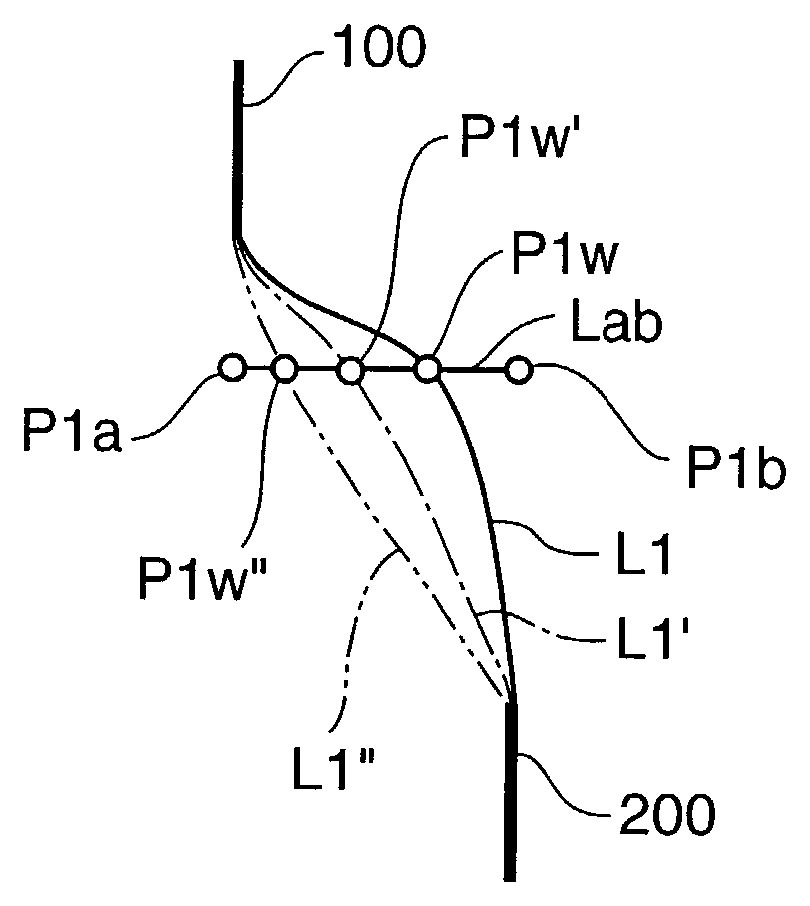
InFIG. 3, the upper model100which is positioned at the upper part of the face (thick line portion in the lower part ofFIG. 3) is associated with the cluster A, the cluster A having a reference point AO; the lower model200which is positioned in the lower part of the face (thick line portion in the lower part ofFIG. 3) is associated with the cluster B, the cluster B having a reference point B0. Referring to a specific vertex P1bof a single polygon which is associated with this cluster B, this vertex is associated with the reference point B0and is transformed to the vertex P1won the lower model200by world co-ordinate transformation matrix Mwb. Also, in the condition of the frame ofFIG. 3, this point P1bcan be expressed as the point P1awhen seen from the cluster A.
Let us now consider the case in which the drawing motion has changed from the frame condition shown inFIG. 3to the frame condition shown inFIG. 4in accordance with progress of the game i.e. the case in which the vertex associated with the cluster B is moved by movement of the reference point B0of cluster B to outside the model (leftwards inFIG. 4). In this situation all of the polygon vertices associated with the cluster B are subjected to a coordinate transformation in the same way as the reference point B0of the cluster B, so the vertex P1bin the lower part of the model200is moved to the position shown inFIG. 4from the position shown inFIG. 3.
In contrast, if the reference point AO of the cluster A does not move, the vertex P1aof upper model100does not move from the position shown inFIG. 3. In this case, upper model100and lower model200constitute part of the surface of the face, so adjacent portions of upper model100and lower model200are constituted by smooth curves etc in accordance with the movement etc of facial muscles: for example, the shape of curve L1shown inFIG. 4(shaded portion inFIG. 4) is naturally produced.
In order to represent a natural condition of deformation the point P1wmay be arranged to be influenced by both the cluster A and the cluster B; it may therefore be arranged to set a new point P1wby finding interior points of the line segment joining the point P1aand the point P1binFIG. 4such that the point P1wis positioned on curve L1, by setting the weightings with which these influences are received in association with the clusters A and B.
If the degree of the association with the cluster A of a given vertex is represented by weighting Ga (%) and the degree of association with the cluster B of this same vertex is represented by weighting Gb (%), the ratios ga (<1) and gb (<1) are respectively expressed by the following expression (4) to expression (7).
ga=Ga/(Ga+Gb)(4)Mga=ga0000ga0000ga00001(5)gb=Gb/(Ga+Gb)(6)Mgb=gb0000gb0000gb00001(7)
It should be noted that Mga and Mgb are the ratios ga and gb expressed in matrix form.
Furthermore, if Mwa represents the co-ordinate transformation matrix for co-ordinate transformation of the cluster A from the local co-ordinate system to the world co-ordinate system and Mwb represents the co-ordinate transformation matrix for co-ordinate transformation of the cluster B from the local co-ordinate system to the world co-ordinate system, the point P1wis expressed by the following expression (8).
P1w=Mga×Mwa×P1a+Mgb×Mwb×P1b(8)
FIG. 5is a diagram given in explanation of the tracks of the lines of adjacent portions, adjusted by weightings. If this processing is explained in image form, as shown inFIG. 5, in respect of the line segment Lab joining the point P1aand the point P1bwhen respectively associated with separate clusters A and B, regarding the values of the ratios ga and gb, if for example the ratio ga is made larger i.e. ratio gb is made small, the point P1wmoves along the line segment Lab from the point P1bto the point P1aas indicated by the point P1w′ and the point P1w″. In this way, the tracks (shapes) of the lines of the adjacent portions of the upper model100and the lower model200can be adjusted from the curve L1to the curve L1′ and the curve L1″.
In this way, by giving the vertex data of the polygons in each range weighting information corresponding to the clusters in prescribed ranges of the models, the shapes of the adjacent portions of the adjacent models100and200can be smoothly joined as shown inFIG. 5so that a representation can be achieved in which smooth deformation is achieved between the models100and200.
Next, a way in which speeding up of the co-ordinate transformation processing of the vertices of the polygons used in the clusters can be achieved will be described. Smoother imaging can be produced by representation of the weightings of adjacent portions using expression (8) described above.
With a standard API such as “OPEN GL” or “DIRECT X” used in the signal processor22, the product of the matrix and the co-ordinates of the respective vertices is employed for representing any desired point on the screen. Consequently, even though the API can achieve high-speed calculation of the first and second term respectively of expression (8), the results of these two calculations are added to obtain a point on the world co-ordinates by a structural portion (hardware or software) other than the aforesaid standard API and the vertex co-ordinates on the world co-ordinates which are obtained as a result must be transferred from this signal processor22to the image drawing processor13together with the unit vector for display purposes, so time is required for this to be done.
Furthermore, although, in the case of vertices that do not have a weighting i.e. that are not associated, co-ordinate transformation can be achieved simply by performing “matrix×vertex co-ordinates”, in the case of vertices that do have a weighting i.e. that are associated, addition: “matrix×vertex co-ordinates”+“matrix×vertex co-ordinates” must be performed a number of times equal to the number of clusters with which the vertex is associated. Consequently, even if an independently created API is applied, it is still necessary to evaluate for each vertex whether or not there is a weighting and to execute different calculation processing in accordance with the result of this evaluation: this tends to slow down the transformation processing and so application to video games is difficult.
A way of speeding up transformation processing will therefore be described with reference toFIG. 3andFIG. 4. The frame inFIG. 3is taken as being frame1representing a field of motion and the co-ordinate transformation matrices Mwa, Mwb in frame1are defined as M1waand M1wb. Also, the frame inFIG. 4is taken as being frame2representing the next field of motion and the co-ordinate transformation matrices Mwa, Mwb in frame2are defined as M2waand M2wb. The points P1aand P1bin frame1ofFIG. 3may then be found from expression (9).
P1w=M1wa×P1a(9)
P1w=M1wb×P1b(10)
Further, expression (9) and expression (10) can be transformed into expression (11) and expression (12) by calculating the inverse co-ordinate transformation matrices M1wa−1and M1wb−1, which are the inverse matrices of the co-ordinate transformation matrices M1waand M1wb.
P1a=M1wa−1×P1w(11)
P1b=M1wb−1×P1w(12)
The point P1ahas the local co-ordinates with respect to the cluster A if the vertex P1is associated only with the cluster A; the point P1bhas the local co-ordinates with respect to the cluster B if the vertex P1is associated only with the cluster B.
The local co-ordinates of vertices that are associated with only a single cluster are fixed in all frames, so the points P1aand P1bin the frame ofFIG. 3correspond to points P1a, P1bin the frame ofFIG. 4; if these points are designated by P2a, P2b, the relationship of these two may be expressed by expression (13) and expression (14).
P2a=P1a(13)
P2b=P1b(14)
Substituting expression (13) and expression (14) into expression (11) and expression (12), respectively, the following expression (15) and expression (16) are obtained:
P2a=M1wa−1×P1w(15)
P2b=M1wb−1×P1w(16)
Consequently, if the point P1win the frame ofFIG. 4is designated as the point P2win the same way as in expression (8), the point P2wis expressed by the following expression (17).
P2w=Mga×M2wa×P2a+Mgb×M2wb×P2b(17)
Next, by substituting expression (15) and expression (16) into expression (17), P2w=Mga×M2wa×M1wa−1×P1w+Mgb×M2wb×M1wb−1×P1wand the following expression (18) is obtained.
P2w=(Mga×M2wa×M1wa−1+Mgb×M2wb×M1wb−1)×P1w(18)
Here, the portion in brackets (Mga×M2wa×M1wa−1+Mgb×M2wb×M1wb−1) on the right-hand side of expression (18) can be expressed as a single matrix, so expression (18) becomes “matrix×vertex co-ordinates” and so can be calculated using only a standard API, as described above. Furthermore, the calculation can be achieved using only the world co-ordinates P1wof a specified frame (in this case frame1ofFIG. 3) as the co-ordinate data, so, in contrast with the case of expression (8), the amount of data can be reduced to that extent.
Regarding the data of the matrix portion (Mga×M2wa×M1wa−1+Mgb×M2wb×M1wb−1), a memory table is provided beforehand that respectively stores co-ordinate transformation matrices M1wa, M1wb, M2waand M2wbdefined as a motion sequence for each frame, so this can be found using the stored data.
FIG. 6is a view showing an example of memory content when co-ordinate transformation matrices in the case where a plurality of clusters are employed are held in a memory table. As shown inFIG. 6, if for example a plurality of clusters a, b, . . . are employed, co-ordinate transformation matrices equal in number to the number of clusters a, b . . . are stored for each frame (1to i) i.e. co-ordinate transformation matrices M1wa, M1wb, . . . , M2wa, M2wb, . . . Miwa, Miwb are stored in a memory table provided by the RAM51etc for each frame.
Next, increasing the efficiency of data compression and processing will be described. In the case of expression (18), there were two clusters associated with a vertex, but, in the models employed in video games, there is no restriction to two clusters and it is necessary to consider the existence of polygons associated with 1 to n clusters. Also, although, in expression (18), the data was based on (M1w, P1w), since the association between the clusters and vertices was calculated based on frame1shown inFIG. 3, since the fundamental frame need not necessarily be frame1ofFIG. 3, hereinbelow this will be indicated by expression (19) as a general formula as below, replacing these by the basis: (M0w, P0w).
Pw=(Σn=1 to Ps(Mg[n]×Mw[n]×M0w[n]−1))×P0w(19)
where
“Σn=1 to Ps” indicates a mathematical notation for summation when n is changed from 1 to Ps.
Pw is the vertex co-ordinates of the world co-ordinates in the frame being found, Ps is the number of clusters associated with the vertex being found, Mg[n] is the weighting matrix expressing the weighting of the cluster associated with the vertex in the frame being found, Mw[n] is the co-ordinate transformation matrix of the cluster associated with the vertex in the frame being found, M0w[n]−1is the fundamental inverse co-ordinate transformation matrix of the cluster of the vertex being found at the time point associated with the cluster and P0ware the world co-ordinates of the vertex being found at the time point associated with the cluster.
From expression (19), the transformation matrix (addition matrix) of the vertex being found at the time point of the frame being found is as follows.
Σn=1 to Ps(Mg[n]×Mw[n]×M0w[n]−1) (20)
where “Σn=1 to Ps” indicates a mathematical notation for summation when n is changed from 1 to Ps.
In the above, there is a very large quantity of data for each vertex, since the above transformation matrix (20) exists at each of all the vertices constituting the model. Also, since such a transformation matrix must be compiled for each vertex, the time required for this computation processing makes it impossible to keep up with the frame period.
Mw [1, 2, . . . , Ps] and M0w [1, 2, . . . , Ps] are the parameters relating to the clusters, so following of all the vertices can be achieved if the matrices of all of the clusters are available. Also, regarding the information for finding the transformation matrices that are characteristic of the vertices, the data for finding the matrices can be reduced by managing the identities of the clusters that are being used by cluster numbers (symbols) constituting identification information for specifying the cluster with which the vertex in question is associated, for each vertex and associating these with the combination of weightings Mg[n] therefor. Specifically, M0w [1, 2, . . . , Ps] are fixed by the model, so they can be made available as model data; Mw [1, 2, . . . , Ps] are co-ordinate transformation matrices of frame unit clusters and so can be made available as model frame data.
FIG. 7is a view showing an example of memory content when symbols specifying the clusters participating in a transformation matrix and the co-ordinate values thereof are held beforehand in a memory table in correspondence with the vertices;FIG. 8is a view showing an example of memory content when the weightings of the clusters associated therewith are held in a memory table in association with the symbols shown inFIG. 7.
As shown inFIG. 7andFIG. 8, if symbols specifying the clusters contributing to the transformation matrices associated with each vertex and their co-ordinate values are stored in a memory table constituted by the RAM51etc and, in addition, the weightings of the associated clusters are stored in the memory table constituted by the RAM51etc in association with the stored symbols, memory capacity can be reduced compared with the case where the cluster weightings constituting the data for finding transformation matrices are stored directly in correspondence with the respective vertices.
The amount of data at each vertex can also be reduced by, when creating a model, restricting beforehand the types of combination of weightings of each of the vertices (i.e. setting these to various types) and managing these combinations using numbers (symbols), transformation matrix numbers (symbols) being allocated to each vertex. Furthermore, rapid calculation of vertex transformation can be achieved by calculating beforehand transformation matrices (20) for all of the combinations, prior to vertex transformation, these results being obtained beforehand (stored during the game period).
FIG. 9is a flow chart showing 3D model deformation processing using the CPU21etc when model data as described above is employed.
First of all, co-ordinate transformation matrices of the clusters in the designated frame are compiled (step ST1) using animation data of the motion that it is desired to reproduce. Next, co-ordinate transformation matrices of the clusters whose weightings have been designated are found from the cluster co-ordinate transformation matrices, using the information regarding management of the combinations of model data weighting (for example the symbols indicated inFIG. 8) (step ST2).
Next, using the data possessed by the vertices, the world co-ordinate data is found (step ST3) by multiplying, using the 3D multiplication processor24etc, the respective vertices with the matrix designated by the number (symbol) of the co-ordinate transformation matrix associated with the vertex in question, and the world co-ordinate data that is thus found is transformed (step ST4) from the co-ordinate system of the virtual camera to the screen co-ordinate system using a prescribed matrix. Graphics drawing (writing to the frame buffer55of the RAM51) in respect of image drawing processor13is then performed (step ST5), in accordance with the vertex data of the screen co-ordinate system that have been obtained.
The following modes of the present invention may be adopted.
(1) This embodiment is likewise applicable also to the normal vector data that is set for each vertex. Specifically, transformation of the normal vectors can also be achieved in the same way as in the case of the co-ordinate positions using expression (18) or expression (19) by utilizing weighted cluster co-ordinate transformation matrices and smoothness of joining can thereby be realized even in respect of the polygon faces.
(2) The model shapes obtained with this embodiment are not restricted to drawing but could also be applied for ascertaining abutment or contact with no feeling of disconformity with other objects while keeping the displayed image the same as in the conventional mode.
(3) While the model data employed in video games typically chiefly comprises polygon model data, the techniques illustrated in this embodiment could also be applied when forming a polygon model by finding a path model or a NURBS model.
(4) Although in this embodiment an example was illustrated in which the joining portions were made smooth by arranging the clusters outside the model, it would be possible to set up prescribed weightings associating polygon vertices constituting this model with internal clusters by arranging (defining) the clusters inside the model.
In summary, the one form of the present invention relates to a recording medium which stores a 3D model deformation program for deforming a 3D model constituted by a plurality of polygons having vertices associated with clusters for specifying an object to be deformed, in correspondence with the drawing period, from data of each frame relating to a motion sequence, said 3D model deformation program causes a video game device to function as: matrix acquisition means that acquires a weighting matrix expressing weightings representing the degree of association of vertices in a certain frame (arbitrary chosen frame or any desired frame) with clusters associated with these vertices, a co-ordinate transformation matrix for transforming the local co-ordinate system of the vertices in the certain frame to a world co-ordinate system and an inverse transformation matrix constituting the inverse matrix of the co-ordinate transformation matrix for transforming the local co-ordinate system of the vertices in a base frame different from the certain frame to the world co-ordinate system; and world co-ordinate calculation means that finds the world co-ordinates of the vertices in the certain frame using the weighting matrix, the co-ordinate transformation matrix, the inverse co-ordinate transformation matrix and the world co-ordinates of the vertices in the base frame.
With the present invention as described in the above, the 3D model deformation program for deforming a 3D model constituted by a plurality of polygons having vertices associated with clusters for specifying an object to be deformed, in correspondence with the drawing period, from data of each frame relating to a motion sequence, causes a video game device to function as: matrix acquisition means that acquires a weighting matrix expressing weightings representing the degree of association of vertices in a certain frame with clusters associated with these vertices, a co-ordinate transformation matrix for transforming the local co-ordinate system of the vertices in the certain frame to a world co-ordinate system and an inverse transformation matrix constituting the inverse matrix of the co-ordinate transformation matrix for transforming the local co-ordinate system of the vertices in a base frame different from the certain frame to the world co-ordinate system; and world co-ordinate calculation means that finds the world co-ordinates of the vertices in the certain frame using the weighting matrix, the co-ordinate transformation matrix, the inverse co-ordinate transformation matrix and the world co-ordinates of the vertices in the base frame.
That is, the video game device acquires a weighting matrix expressing weightings representing the degree of association of vertices in a certain frame with clusters associated with these vertices, a co-ordinate transformation matrix for transforming the local co-ordinate system of the vertices in the certain frame to a world co-ordinate system and an inverse transformation matrix constituting the inverse matrix of the co-ordinate transformation matrix for transforming the local co-ordinate system of the vertices in a base frame different from the certain frame to the world co-ordinate system; and finds the world co-ordinates of the vertices in the certain frame using the weighting matrix, co-ordinate transformation matrix, inverse co-ordinate transformation matrix and the world co-ordinates of the vertices in the base frame.
In this way, the world co-ordinates of a vertex in any desired frame can be found from the weighting matrix and co-ordinate transformation matrix in any desired frame (certain frame) and the inverse co-ordinate transformation matrix and the world co-ordinates of the vertex in a specified frame (base frame), so transformation processing of a 3D model using clusters can be performed at high speed. Also, since there is no need to store beforehand in prescribed memory the world co-ordinates of the vertices in each frame, the storage capacity of the memory can be reduced. Thus, the deformation processing of a 3D model using clusters can be performed in each drawing period in a video game and memory storage capacity can be reduced.
In the aforementioned invention, the video game device can be further caused to function as addition means for finding an addition matrix obtained by finding the product of the weighting matrix, the co-ordinate transformation matrix and the inverse co-ordinate transformation matrix for each cluster with which a vertex is associated, and adding these products; and the world co-ordinate calculation means finds the world co-ordinates of a vertex in the certain frame from the product of the addition matrix and the world co-ordinates of the vertex in the base frame.
With the aforementioned features, the 3D model deformation program further causes the video game device to function as addition means for finding an addition matrix obtained by finding the product of the weighting matrix, co-ordinate transformation matrix and inverse co-ordinate transformation matrix for each cluster with which a vertex is associated, and adding these products; and the world co-ordinate calculation means finds the world co-ordinates of a vertex in the certain frame from the product of the addition matrix thus found and the world co-ordinates of the vertex in the base frame.
That is, the addition matrix is obtained by finding the product of the weighting matrix, co-ordinate transformation matrix and inverse co-ordinate transformation matrix for each cluster with which a vertex is associated, and adding these products that are obtained; and the world co-ordinates of a vertex in the certain frame are found from the product of the addition matrix thus found and the world co-ordinates of the vertex in the base frame.
In this way, the world co-ordinates of a vertex in any desired frame (a certain frame) can be found using a standard API (Application Programming Interface), so 3D model deformation processing can be performed at high speed. Accordingly, vertex world co-ordinates can be found in any desired frame solely by the product of an addition matrix and vertex co-ordinates, so 3D model deformation processing can be performed at high speed in each frame period using a standard API.
In the aforementioned invention, the base frame can be set as the first frame relating to a motion sequence.
With the above feature, the base frame is the first (initial) frame relating to a motion sequence, so the world co-ordinates of a vertex in all of the second and subsequent frames can be found from the world co-ordinates of the vertex in the base frame. Accordingly, the world co-ordinates of all of the vertices in the second and subsequent frames can be found from the world co-ordinates of the vertices in the first frame, so the need to store beforehand the world co-ordinates of the vertices in all of the second and subsequent frames is eliminated, making it possible to reduce memory storage capacity.
In the aforementioned invention, the co-ordinate transformation matrix can be stored beforehand in a memory table for each frame.
With the features described in the above, since the co-ordinate transformation matrix is stored beforehand in a memory table for each frame, the necessary co-ordinate transformation matrix can be acquired simply by reading the co-ordinate transformation matrix for transforming the memory table. Thus, 3D model deformation processing using clusters can be performed more rapidly.
In the aforementioned invention, the clusters can be managed by the attachment of identification information for specifying a cluster with which the vertex in question is associated, for each vertex. Since the clusters are managed by the attachment of identification information for specifying a cluster with which the vertex in question is associated, for each vertex, the clusters with which a vertex is associated can be specified from this identification information, so the clusters associated with each vertex can easily be specified. Thus, the clusters associated with each vertex can easily be specified, so 3D model deformation processing using clusters can be performed easily.
In the aforementioned invention, a weighting can be set in association with the identification information.
With the above features, since a weighting is set in association with the identification information for specifying clusters with which a vertex is associated, compared with directly setting the weightings at each vertex, the volume of data that needs to be stored can be reduced.
Furthermore, the present invention takes a form of a 3D model deformation method for deforming, using a video game device, a 3D model constituted by a plurality of polygons having vertices associated with clusters for specifying an object to be deformed, in correspondence with the drawing period, from data of each frame relating to a motion sequence, including: a matrix acquisition step wherein the video game device acquires a weighting matrix expressing weightings representing the degree of association of vertices in a certain frame with clusters associated with these vertices, a co-ordinate transformation matrix for transforming the local co-ordinate system of the vertices in the certain frame to a world co-ordinate system and an inverse transformation matrix constituting the inverse matrix of the co-ordinate transformation matrix for transforming the local co-ordinate system of the vertices in a base frame different from the certain frame to the world co-ordinate system; and a world co-ordinate calculation step wherein the video game device finds the world co-ordinates of the vertices in the certain frame using the weighting matrix, the co-ordinate transformation matrix, the inverse co-ordinate transformation matrix and the world co-ordinates of the vertices in the base frame.
In the aforementioned form of the invention, the 3D model deformation method for deforming, using a video game device, a 3D model constituted by a plurality of polygons having vertices associated with clusters for specifying an object to be deformed, in correspondence with the drawing period, from data of each frame relating to a motion sequence, includes: a matrix acquisition step wherein the video game device acquires a weighting matrix expressing weightings representing the degree of association of vertices in a certain frame with clusters associated with these vertices, a co-ordinate transformation matrix for transforming the local co-ordinate system of the vertices in the certain frame to a world co-ordinate system and an inverse transformation matrix constituting the inverse matrix of the co-ordinate transformation matrix for transforming the local co-ordinate system of the vertices in a base frame different from the certain frame to the world co-ordinate system; and a world co-ordinate calculation step wherein the video game device finds the world co-ordinates of the vertices in the certain frame using the weighting matrix, co-ordinate transformation matrix, inverse co-ordinate transformation matrix and the world co-ordinates of the vertices in the base frame.
That is, the video game device acquires a weighting matrix expressing weightings representing the degree of association of vertices in a certain frame with clusters associated with these vertices, a co-ordinate transformation matrix for transforming the local co-ordinate system of the vertices in the certain frame to a world co-ordinate system and an inverse transformation matrix constituting the inverse matrix of the co-ordinate transformation matrix for transforming the local co-ordinate system of the vertices in a base frame different from the certain frame to the world co-ordinate system; and finds the world co-ordinates of the vertices in the certain frame using the weighting matrix, co-ordinate transformation matrix, inverse co-ordinate transformation matrix and the world co-ordinates of the vertices in the base frame.
In this way, since the world co-ordinates of a vertex in any desired frame can be found from the weighting matrix and co-ordinate transformation matrix in any desired frame (certain frame) and the inverse transformation matrix and world co-ordinates of the vertex in a specified frame (base frame), deformation processing of a 3D model using clusters can be performed at high speed. Also, since there is no need to store beforehand in prescribed memory the world co-ordinates of the vertices in each frame, the memory storage capacity can be reduced. With the present invention, the world co-ordinates of vertices in any desired frame can be found from a weighting matrix and co-ordinate transformation matrix in any desired frame and an inverse co-ordinate transformation matrix and vertex world co-ordinates in a specific frame, so deformation processing of a 3D model using clusters can be performed in each drawing period in a video game and memory storage capacity can be reduced.
The present invention also takes a form of a video game device wherein a 3D model constituted by a plurality of polygons having vertices associated with clusters for specifying an object to be deformed, is deformed in correspondence with the drawing period, from data of each frame relating to a motion sequence, comprising: matrix acquisition means that acquires a weighting matrix expressing weightings representing the degree of association of vertices in a certain frame with clusters associated with these vertices, a co-ordinate transformation matrix for transforming the local co-ordinate system of the vertices in the certain frame to a world co-ordinate system and an inverse transformation matrix constituting the inverse matrix of the co-ordinate transformation matrix for transforming the local co-ordinate system of the vertices in a base frame different from the certain frame to the world co-ordinate system; and world co-ordinate calculation means that finds the world co-ordinates of the vertices in the certain frame using the weighting matrix, the co-ordinate transformation matrix, the inverse co-ordinate transformation matrix and the world co-ordinates of the vertices in the base frame.
In the present invention as described above, a video game device wherein a 3D model constituted by a plurality of polygons having vertices associated with clusters for specifying an object to be deformed, is deformed in correspondence with the drawing period, from data of each frame relating to a motion sequence, comprises: matrix acquisition means that acquires a weighting matrix expressing weightings representing the degree of association of vertices in a certain frame with clusters associated with these vertices, a co-ordinate transformation matrix for transforming the local co-ordinate system of the vertices in the certain frame to a world co-ordinate system and an inverse transformation matrix constituting the inverse matrix of the co-ordinate transformation matrix for transforming the local co-ordinate system of the vertices in a base frame different from the certain frame to the world co-ordinate system; and world co-ordinate calculation means that finds the world co-ordinates of the vertices in the certain frame using the weighting matrix, co-ordinate transformation matrix, inverse co-ordinate transformation matrix and the world co-ordinates of the vertices in the base frame.
That is, the video game device acquires a weighting matrix expressing weightings representing the degree of association of vertices in a certain frame with clusters associated with these vertices, a co-ordinate transformation matrix for transforming the local co-ordinate system of the vertices in the certain frame to a world co-ordinate system and an inverse transformation matrix constituting the inverse matrix of the co-ordinate transformation matrix for transforming the local co-ordinate system of the vertices in a base frame different from the certain frame to the world co-ordinate system; and finds the world co-ordinates of the vertices in the certain frame using the weighting matrix, co-ordinate transformation matrix, inverse co-ordinate transformation matrix and the world co-ordinates of the vertices in the base frame.
In this way, since the world co-ordinates of a vertex in any desired frame can be found from the weighting matrix and co-ordinate transformation matrix in any desired frame (certain frame) and the inverse transformation matrix and world co-ordinates of the vertex in a specified frame (base frame), deformation processing of a 3D model using clusters can be performed at high speed. Also, since there is no need to store beforehand in prescribed memory the world co-ordinates of the vertices in each frame, the memory storage capacity can be reduced.
With the present invention in the above form, the world co-ordinates of vertices in any desired frame can be found from a weighting matrix and co-ordinate transformation matrix in any desired frame and an inverse co-ordinate transformation matrix and vertex world co-ordinates in a specific frame, so deformation processing of a 3D model using clusters can be performed in each drawing period in a video game and memory storage capacity can be reduced.
This application is based on Japanese patent application serial no. 2001-326122, filed in Japan Patent Office on Oct. 24, 2001, the contents of which are hereby incorporated by reference.
Although the present invention has been fully described by way of example with reference to the accompanying drawings, it is to be understood that various changes and modifications will be apparent to those skilled in the art. Therefore, unless otherwise such changes and modifications depart from the scope of the present invention hereinafter defined, they should be construed as being included therein.
Claims
- A recording medium storing an executable 3D model deformation program for configuring a video game device to function as: a storage device storing data representing a 3D model of an object to be deformed, the 3D model including a plurality of polygons having vertices associated with clusters, the clusters being unrelated to a skeleton, the data representing frames relating a sequence of motions and which are sequentially displayed based on a drawing period, the frames including a base frame and a relevant frame wherein the 3d model is deformed relative to said base frame;matrix acquisition means for acquiring: a weighting matrix expressing weightings representing the degree of association of vertices in the relevant frame with clusters associated with these vertices, a co-ordinate transformation matrix for transforming co-ordinates of the vertices in said relevant frame represented by a local co-ordinate system to a world co-ordinate system, and an inverse transformation matrix constituting an inverse matrix of a co-ordinate transformation matrix for transforming co-ordinates of vertices in the base frame represented by the local co-ordinate system to co-ordinates of the vertices of the base frame represented by the world co-ordinate system;and world co-ordinate calculation means for calculating the world co-ordinates of the vertices in said relevant frame using said weighting matrix, said co-ordinate transformation matrix, said inverse co-ordinate transformation matrix and the co-ordinates of the vertices in said base frame represented in the world co-ordinate system.
- The recording medium according to claim 1 , wherein the 3D model deformation program further causes said video game device to function as summation means for a summation matrix obtained by: finding products of said weighting matrix, said co-ordinate transformation matrix and said inverse co-ordinate transformation matrix for each of associated clusters of said clusters with which a given one of said vertices is associated, and adding the products;wherein said world co-ordinate calculation means finds the world co-ordinates of said given one of the vertices in said relevant frame from the product of said summation matrix and the world co-ordinates of said given one of the vertices in said base frame.
- The recording medium according to claim 1 , wherein said base frame is the first frame relating to a motion sequence.
- The recording medium according to claim 1 , wherein said co-ordinate transformation matrix is stored beforehand in a memory table for each frame.
- The recording medium according to claim 1 , wherein for each of said vertices, said clusters are managed by attachment of identification information for specifying said associated clusters with which said given one of the vertices is associated.
- The recording medium according to claim 5 , wherein a weighting is set in association with said identification information.
- A 3D model deformation method using a video game device, comprising: storing data representing a 3D model of an object to be deformed, the 3D model including a plurality of polygons having vertices associated with clusters, the clusters being unrelated to a skeleton the data representing frames relating a sequence of motions and which are sequentially displayed based on a drawing period, the frames including a base frame and a relevant frame wherein the 3d model is deformed relative to said base frame;operating said video game device to acquire: a weighting matrix expressing weightings representing the degree of association of vertices in the relevant frame with clusters associated with these vertices, a co-ordinate transformation matrix for transforming co-ordinates of the vertices in said relevant frame represented by a local co-ordinate system to a world co-ordinate system, and an inverse transformation matrix constituting an inverse matrix of a co-ordinate transformation matrix for transforming co-ordinates of vertices in the base frame represented by the local co-ordinate system to co-ordinates of the vertices of the base frame represented by the world co-ordinate system;and operating said video game device to calculate the world co-ordinates of the vertices in said relevant frame using said weighting matrix, said co-ordinate transformation matrix, said inverse co-ordinate transformation matrix and the co-ordinates of the vertices in said base frame represented in the world co-ordinate system.
- A video game device, comprising: a storage device storing data representing a 3D model of an object to be deformed, the 3D model including a plurality of polygons having vertices associated with clusters, the clusters being unrelated to a skeleton, the data representing frames relating a sequence of motions and which are sequentially displayed based on a drawing period, the frames including a base frame and a relevant frame wherein the 3d model is deformed relative to said base frame;matrix acquisition means for acquiring: a weighting matrix expressing weightings representing the degree of association of vertices in the relevant frame with clusters associated with these vertices, a co-ordinate transformation matrix for transforming co-ordinates of the vertices in said relevant frame represented by a local co-ordinate system to a world co-ordinate system, and an inverse transformation matrix constituting an inverse matrix of a co-ordinate transformation matrix for transforming co-ordinates of vertices in the base frame represented by the local co-ordinate system to co-ordinates of the vertices of the base frame represented by the world co-ordinate system;and world co-ordinate calculation means for calculating the world co-ordinates of the vertices in said relevant frame using said weighting matrix, said co-ordinate transformation matrix, said inverse co-ordinate transformation matrix and the co-ordinates of the vertices in said base frame represented in the world co-ordinate system.
Disclaimer: Data collected from the USPTO and may be malformed, incomplete, and/or otherwise inaccurate.