U.S. Pat. No. 7,104,890
PROGRAM, RECORDING MEDIUM, GAME CHARACTER RENDERING METHOD, AND GAME APPARATUS
AssigneeKoei Co., Ltd.
Issue DateDecember 20, 2002
Illustrative Figure
Abstract
A program which can dynamically and realistically express an impact which a game character rendered by motion data receives is provided. In bullet ball-related processing (S114), determination is made about whether a bullet ball hits either one of node assigned balls. When the determination is affirmative, a torque at a hit point is calculated as an impact magnitude and the node assigned balls are disposed, through calculation of a rotation angle per frame, to nodes whose coordinate positions are corrected in metaball update processing (S120), density is calculated for each vertex of voxels from a reference position of each metaball towards the minimum direction and the maximum direction of a voxel index of the voxels according to a calculation equation expressing a solid shape in density distribution processing (S122), and vertex coordinates of polygons are calculated based upon density of each metaball at the vertex coordinates of the voxels and a predetermined threshold in marching cube processing (S124).
Description
DETAILED DESCRIPTION OF THE PREFERRED EMBODIMENTS An embodiment where the present invention is applied to a video game will be explained with reference to the drawings. (Structure) As shown inFIG. 1, in a video game apparatus for home use10where a video game according to this embodiment is performed, a game apparatus main body2is connected with a display such as a television monitor4housing a speaker5therein and with an input apparatus3. The game apparatus main body2has a medium reading section (refer toFIG. 3) to which a recording medium1such as a CD-ROM or the like can be installed. A game program and game data recorded on the recording medium1is automatically loaded to a storing memory inside the game apparatus main body2by installing the recording medium to the medium reading section. As shown inFIG. 2, various buttons such as a start button30for starting a game, a square button31, a triangular button32, a circular button33, and an x shaped button34for operating a game character or for responding to a selection inquiry from the game apparatus main body2, and a + shaped direction button set comprising a up (⇑) button35, a right (→) button36, a left (←) button37and a down (⇓) button38, and the like are disposed at the input apparatus3. As shown inFIG. 3, the game apparatus main body2is provided with a CPU block20serving as a computer for implementing control on the entire apparatus. The CPU block20is configured with a SCU (System Control Unit) for controlling data transmission among respective sections in the game apparatus main body2, a CPU operating as a central processing unit at a high clock speed and serving as respective elements in claims described later, a ROM in which a basic control operation of the game apparatus main body2is stored, a RAM serving as a work area for the CPU and ...
DETAILED DESCRIPTION OF THE PREFERRED EMBODIMENTS
An embodiment where the present invention is applied to a video game will be explained with reference to the drawings.
(Structure)
As shown inFIG. 1, in a video game apparatus for home use10where a video game according to this embodiment is performed, a game apparatus main body2is connected with a display such as a television monitor4housing a speaker5therein and with an input apparatus3. The game apparatus main body2has a medium reading section (refer toFIG. 3) to which a recording medium1such as a CD-ROM or the like can be installed. A game program and game data recorded on the recording medium1is automatically loaded to a storing memory inside the game apparatus main body2by installing the recording medium to the medium reading section.
As shown inFIG. 2, various buttons such as a start button30for starting a game, a square button31, a triangular button32, a circular button33, and an x shaped button34for operating a game character or for responding to a selection inquiry from the game apparatus main body2, and a + shaped direction button set comprising a up (⇑) button35, a right (→) button36, a left (←) button37and a down (⇓) button38, and the like are disposed at the input apparatus3.
As shown inFIG. 3, the game apparatus main body2is provided with a CPU block20serving as a computer for implementing control on the entire apparatus. The CPU block20is configured with a SCU (System Control Unit) for controlling data transmission among respective sections in the game apparatus main body2, a CPU operating as a central processing unit at a high clock speed and serving as respective elements in claims described later, a ROM in which a basic control operation of the game apparatus main body2is stored, a RAM serving as a work area for the CPU and temporarily storing game programs and various data recorded on the recording medium1, and an internal bus for connecting these configurations.
An external bus25is connected to the SCU. The external bus25is connected to an input receiving section21which receives an input from the input apparatus3such as a controller pad or the like to transmit input information to the CPU block20, a medium reading section22, such as a CD-ROM drive or the like, which is provided with a unillustrated sub-CPU and reads a game program including game data recorded on the recording medium1to transfer the read game program to the CPU block20, an image processing section23which is provided with a CPU and a VRAM for performing graphic processing and performs texture processing, light source processing and the like to an object according to information fed from the CPU block20in order to implement rendering (graphically expressing) processing in a three-dimensional field, and a sound processing section24which is provided with a unillustrated sub-CPU and which processes sounds such as, for example, back music, fighting sounds and the like. Also, the input receiving section21is connected to the input apparatus3, the image processing section23to the television monitor4, and the sound processing section24to the speaker5housed in the television monitor4.
(Operation)
Next, an operation of the video game apparatus for home use10will be explained mainly on the basis of the CPU of the CPU block20with reference to flowcharts. Incidentally, when the game apparatus main body2is supplied with a power source and the recording medium1is inserted therein, a metaball rendering routine for dynamically rendering an object constituted with metaballs in a three-dimensional imaginary space is executed.
As shown inFIG. 4, in the metaball rendering routine, firstly, an initial setting processing is performed in step102. In this initial setting processing, game data including object information such as motion data of nodes (joints) for each frame of a character, hierarchy data of nodes, shapes, sizes and the like of metaballs constituting a character, and a game program are loaded to the RAM, and initial values of time t and motion cursor (frame counter) mc are respectively set to 0.
Next, in step104, determination is made about whether or not a vertical retrace line interruption (Vsync) synchronizing with a vertical blanking cycle of the television monitor4, which is performed at a cycle of once per 1/60 sec. (16.6 milliseconds), is carried out. When the determination is negative, in the next step106, main processing such as input processing for processing input information transferred from the input receiving section21, sound processing for causing the sound processing section24to compose game effect sound, or the like is performed, and the routine proceeds to step110.
On the other hand, when the determination in step104is affirmative, a rendering calculation processing subroutine for disposing/rendering an object constituted with metaballs in a three-dimensional imaginary space (imaginary frame described later) is performed in step108.
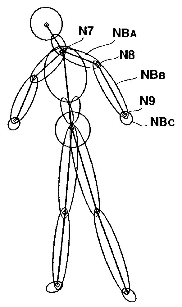
Here, an outline of the object including a character which is rendered in this embodiment will be explained. As shown inFIGS. 20A and 20B, a character c has a plurality of nodes N1to N11corresponding to human joints. As shown inFIG. 21, the nodes N1to N11constitute hierarchy (parentage), and distances between the respective notes N are constant. These nodes N are not displayed on the television monitor4. As shown inFIG. 22, the nodes N are assigned (disposed) with a plurality of metaballs (hereinafter, refer to as “node assigned balls”) NB, and the character c such as shown inFIG. 21Ais displayed on the television monitor4via density distribution processing and marching cube processing described later for respective of the node assigned balls NB. Incidentally, when the term “an object” is used in this embodiment, the term includes subjects other than the character c rendered in the three-dimensional imaginary space. That is, as shown in the following Table 1, there are a plurality of kinds of metaballs and details thereof will be described later.
TABLE 1KIND OF METABALLOUTLINENode assigned Balla ball assigned to a node and(NB)constitutes a body of a characterGround Ball (GB)a ball crawling on the ground(constituted by plural balls)Droplet Ball (DB)a ball dropping from a specificnode assigned ballTentacle Ball (TB)a ball constituting a slendertentacle projecting from aspecific node assigned ballBullet Ball (BB)a ball constituting a bullet whichis shot when a player attacks acharacterFragment Ball (FB)a ball scattered when a bullet ballhits a node assigned ball
As shown inFIG. 5, in the rendering calculation processing subroutine, motion data for the nodes N1to N11of the character c in the current frame are obtained corresponding to the motion cursor mc in step112. Such motion data are formed with scale information, rotation information and translation information, and a motion can be expressed by calculating matrixes having 4 rows×4 columns for each frame as disclosed, for example, in “3-DIMENSIONAL COMPUTER GRAPHICS” co-authored by Eihachiro Nakamae and Tomonori Nishida and published by Shokoudou Inc.
In the next step114, a bullet ball-related processing subroutine for processing a bullet ball BB shot when a player attacks the character c is carried out. As shown inFIG. 23, a player can attack the character c by operating the input apparatus3to shoot a bullet ball BB. Namely, as shown inFIG. 2, a player can shoot a bullet ball BB by operating the + shaped direction button set of the input apparatus3to locate a cursor on the character c and push the circular button33. In the main processing in step106described above, the position of the cursor (hitting target coordinates of the bullet ball BB) is fetched when the circular button33is pushed, and (a status value of) a bullet ball status flag bbfl expressing a status that a bullet ball BB is shot is changed from 0 to 1. Incidentally, in this embodiment, a case that one bullet ball BB is shot will be explained for simplifying an explanation, but it is possible to shoot a plurality of bullet balls BB.
As shown inFIG. 6, in the bullet ball-related processing subroutine, determination is made in step142about whether or not the bullet ball status flag bbfl is 1. When the determination is negative, the bullet ball-related processing subroutine is terminated because a bullet ball BB has not been shot yet, and the routine proceeds to step116inFIG. 5. When the determination is affirmative, determination is made in the next step144about whether or not the bullet ball status flag bbfl is changed from 0 to 1 by comparing the bullet ball status flag bbfl of the previous vertical blanking interruption time (before 1/60 seconds) with the current bullet ball status flag bbfl in order to judge as to whether or not a bullet ball BB has just been shot by a player.
When the determination is affirmative in step144, a velocity vector VBof the bullet ball BB is calculated and memorized in the RAM in the next step146. A shooting position coordinate of the bullet ball BB is predetermined, and a magnitude (a scalar value) of a velocity (initial velocity) of the bullet ball BB is provided in advance. Accordingly, a directional vector directing from the shooting position coordinate to the hitting target coordinates of the bullet ball BB is calculated, and then the velocity vector VBcan be obtained by multiplying the directional vector and the scalar value of the velocity of the bullet ball BB together (refer toFIG. 23). Here, a directional vector is defined as a unit vector (x, y, z) which has no meaning about its magnitude but has a meaning about its direction only. The directional vector (x, y, z) in this case can be obtained by calculating a difference from the hitting target coordinate (x, y, z) to the shooting position coordinate (x, y, z) to produce the unit vector. Also, instep146, a distance between the hitting target coordinate and the shooting position coordinate is calculated and memorized in the RAM. Incidentally, a velocity of a bullet ball BB is handled as a fixed value, and a speed damping due to air frictional resistance is not considered.
In the next step148, the position of the bullet ball BB is calculated and memorized in the RAM, and the bullet ball-related processing subroutine is terminated and the routine proceeds to step116inFIG. 5. Assuming that P0is a shooting position coordinate P(x, y, z) of the bullet ball BB, a position P of the bullet ball BB can be obtained according to an equation of P=P0+VB·( 1/60) for each component of the three-dimensional coordinate axes x, y and z.
On the other hand, when the negative determination is made in step144, the current position P of the bullet ball BB is calculated and memorized in the RAM in step150. Assuming that Pt−1is a position at the previous vertical blanking interruption time and δt is a time of the vertical blanking interruption ( 1/60 seconds), the current position P of the bullet ball BB can be obtained for each component of the three-dimensional coordinate axes x, y and z by using an equation of P=Pt−1+VB·δt. Accordingly, in step150, the latest position (x, y, z) of the bullet ball BB is calculated on the basis of the position last time for each vertical blanking interruption time and is memorized in the RAM. Incidentally, the equations for calculating the position P of the bullet ball BB used in step148and step150are expressed in a state that the third term of the Euler's motion equations is deleted because the velocity vector VBof the bullet ball BB is constant (acceleration=0).
Next, in step152, determination is made about whether or not the bullet ball BB hits any one of the node assigned balls NB. That is, center coordinates C for all node assigned balls NB assigned to node N in the current frame are calculated (described in detail later), and determination is made about whether or not a (center) position P of the bullet ball BB is in a predetermined radius d of respective of the center coordinates C for the node assigned balls NB, as shown inFIG. 24A. When the bullet ball BB is positioned in the predetermined radius d of a plurality of node assigned balls, it is considered that the bullet ball BB hits a node assigned ball NB which has the nearest distance to the bullet ball BB. Incidentally, in this embodiment, when a radius of the node assigned ball NB constituting a head of the character c is set to 30 to 40, a radius of the bullet ball BB is set to 20 to 30 (when these are actually displayed on the television monitor4, these sizes become smaller, as described later).
When the negative determination is made in step152, determination is made in the next step154about whether or not a y component (vertical direction coordinate component) of the position P of the bullet ball BB has reached the ground or positioned below it (y≦0). When the determination is affirmative, the subroutine proceeds to step158. On the other hand, when the determination is negative, determination is made in step156about whether or not the position P of the current bullet ball BB reached a 1.5 times distance (a predetermined distance) as long as a distance between the hitting target coordinate calculated in advance in step146and the shooting position coordinate. When the determination is negative, the bullet ball-related processing subroutine is terminated and the routine proceeds to step116inFIG. 5. When the determination is affirmative, the bullet ball status flag bbfl is reset from 1 to 0 in the next step155, and the bullet ball-related processing subroutine is terminated and the routine proceeds to step116inFIG. 5. Accordingly, in case that the bullet ball BB does not hit the node assigned ball NB of the character c, when the position P becomes below the ground (y<0) or when the bullet ball BB reaches the predetermined distance, the bullet ball status flag bbfl is set to 0. Incidentally, when the bullet ball status flag bbfl becomes 0, the bullet ball BB is extinguished.
On the other hand, when the determination is affirmative in step152, hit flags shfl of a specific node assigned ball NB which the bullet ball BB hit and of lower node assigned balls NB therefrom are changed from 0 to 1 in step160. That is, all the node assigned balls NB have their hit flags shfl, and the hit flags are usually set to 0. As shown inFIG. 22andFIG. 23, for example, when the bullet ball BB hit a node assigned ball NBAassigned to a node N7, hit flags shfl of node assigned balls NBBand NBcassigned to nodes N8and N9which are hierarchically lower than the node N7are also changed from 0 to 1 according to hierarchy information shown inFIG. 21. Actually, the node assigned balls NBA, NBBand the like shown inFIG. 23are respectively divided into about three node assigned balls, which are assigned to the nodes N7, N8, N9or portions between these nodes, and actual hierarchy is more complicated than the hierarchy shown inFIG. 21. In this embodiment, however, such a constitution is employed that respective of the node assigned balls NBA, NBBand the like are assigned to respective of the node assigned balls, for simplicity of an explanation.
Next, in step162, as shown inFIG. 24B, a plurality of fragmentary balls FB are generated. Here, the fragmentary balls FB are defined as balls scattered when the bullet ball BB hit a node assigned ball NB (refer to TABLE 1), and they are generated at positions which are angled at 0°, ±30° and ±60° to the direction of the velocity vector VBof the bullet ball BB from a hit point H (a center point of the bullet ball BB) at a side opposed to the side of the hit point H of the node assigned ball NB which was hit by the bullet ball BB. The respective fragmentary balls FB have different sizes for expressing dispersion and, for example, assuming that an average radius thereof is 5, their radii are randomly set to 4 or 6 such that they have radii of about ±1 on the average radius. Also, in step162, velocity vectors of the respective fragmentary balls FB are calculated and memorized in the RAM. In order to express dispersion of the respective fragmentary balls FB in velocity, a dispersion coefficient “a” (0.5≦a≦1) is introduced. For example, a velocity of the fragmentary ball FB generated at an angle of 0° from the hit point H can be obtained by multiplying the same directional vector as the directional vector of the bullet ball BB before it is hit by both a scalar value of the velocity vector of the bullet ball BB before it is hit and a dispersion coefficient “a” randomly obtained within a range of 0.5≦a≦1. Velocity vectors of the generated fragmentary balls at angles of ±30° and ±60° can be obtained by calculating directional vectors at angles of ±30° and ±60° first, and multiplying respective of these directional vectors by both the scalar value of the velocity vector of the bullet ball BB before hitting and a dispersion coefficient “a” randomly obtained within the range of 0.5≦a≦1.
Next, in order to express a state that the bullet ball BB hit a node assigned ball NB constituting the character c and stopped therein (refer toFIG. 31A), a velocity vector of the bullet ball BB is set to (0, 0, 0) in step164, 30 is subtracted from a power nbp of the hit node assigned ball NB in step166, and determination is made in step168about whether or not the power nbp of the hit node assigned ball NB becomes less than 0. That is, 100 is given to each node assigned ball NB as the power nbp in the initial setting processing in step102, and when four bullet balls BB hit the same node assigned ball NB, the power nbp of the node assigned ball NB becomes less than 0.
When the determination is negative in step168, the bullet ball-related processing subroutine is terminated and the routine proceeds to step116inFIG. 5. When the determination is affirmative, after status flags nbfl of the node assigned ball NB and node assigned balls NB hierarchically lower than the node assigned ball are set to “Collapse” and memorized in the RAM in the next step170, the bullet ball-related processing subroutine is terminated and the routine proceeds to step116inFIG. 5. Explanation will be further made along the above-described example. As shown inFIG. 22, when a bullet ball BB hit the node assigned ball NBAassigned to the node N7, status flags nbfl of the node assigned balls NBBand NBCassigned to the nodes N8and N9lower than the node N7are also changed from “Normal” to “Collapse”. Here, the term “Normal” means a state that a node assigned ball NB is at a position assigned to the node N to which it is to be assigned (refer toFIG. 22), and the term “Collapse” means a state that the node assigned ball NB (for example, NBA, NBB, NBC) separates from (is torn off) the position assigned to the node N (for example, N7) to which it is to be assigned to drop naturally.
In step116inFIG. 5, an explosion-related processing subroutine for performing processing relating to explosion of all the node assigned balls NB constituting the character c is carried out. As shown inFIG. 7, in the explosion-related processing subroutine, a sum total (Σnbp) of the powers nbp of all the node assigned balls NB is calculated in step182, and it is determined in the next step184about whether or not the sum total of the powers nbp of all the node assigned balls NB is 50% or less of the sum total of the powers in the initial setting processing. As described above, the power nbp of each node assigned ball NB in the initial setting processing is 100, and when the number of the node assigned balls NB is 18 as shown inFIG. 22, it is determined that Σnbp is 900 or less.
When the determination is negative, it is determined that the character c is not exploded and the explosion-related processing subroutine is terminated and the routine proceeds to step118inFIG. 5. On the other hand, when the determination is affirmative, the status flags nbfl of all the node assigned balls NB are set to “Explosion” in step186, and after spreading order (spreading start time) for all the node assigned balls NB is calculated and memorized in the RAM in the next step188, the explosion-related processing subroutine is terminated and the routine proceeds to step118inFIG. 5.
When the status flag nbfl of the node assigned ball NB becomes “Explosion”, the node assigned balls NB constituting the character c are scattered (spread) as oval spherical fragments. Such processing can be employed that all the node assigned balls NB are simultaneously or randomly scattered, however, they are scattered in a time-wise random manner in this embodiment. The center of the explosion becomes a node assigned ball NB which the bullet ball BB hit in step152inFIG. 6. When the node assigned ball NBAshown inFIG. 22is the center of explosion, the spreading order is set such that time differences occur among respective spreading start times ts, such as, for example, a spreading start time ts of the node assigned balls NBA, NBB, NBCassigned to the nodes N7, N8, N9=0 (the present time), a spreading start time ts of the node assigned balls NB assigned to the nodes N7, N10, N11=20 (after 20/60 seconds from the present time), a spreading start time ts of the node assigned balls NB assigned to the nodes N7, N6=40, a spreading start time ts of the node assigned balls NB assigned to the nodes N7, N1=60, a spreading start time ts of the node assigned balls NB assigned to the nodes N1, N2, N3=80, and a spreading start time ts of the node assigned balls NB assigned to the nodes N1, N4, N5=100. Also, regarding a direction and an initial velocity of each node assigned ball NB at a time of starting spreading, each initial spreading velocity vector V0is predetermined such that all the node assigned balls NB are scattered in almost all directions according to explosion.
In step118inFIG. 5, determination is made about whether or not metaball update processing and density distribution processing described later are completed regarding all the metaballs. When the determination is negative, a metaball update processing subroutine for updating (producing) object information on the metaballs is performed in step120.
As shown inFIG. 8, in the metaball update processing subroutine, determination is made in step212about whether or not a subject to be processed is a node assigned ball NB. When the determination is affirmative, a node assigned ball processing subroutine describe later is performed in step214, and when the determination is negative, determination is made in step216about whether or not the subject to be processed is a ground ball GB. The term “ground ball GB” is defined as a ball which crawls on the ground according to movement of the character c and is disposed just below the character c (refer to TABLE 1,FIG. 20A), and it is displayed on the television monitor4as it is a puddle or a pool disposed just below the character c. When the determination is affirmative, a ground ball processing subroutine described later is performed in step218. When the determination is negative, determination is made in step220about whether the subject to be processed is a tentacle ball TB. The term “tentacle ball TB” means a ball which constitutes a slender tentacle projecting (protruding) from a specific node assigned ball (refer to TABLE 1,FIG. 20A). When the determination is affirmative, a tentacle ball processing subroutine described later is performed in step222. When the determination is negative, determination is made in step224about whether or note the subject to be processed is a bullet ball BB. When the determination is affirmative, a bullet ball processing subroutine described later is performed in step226. When the determination is negative, determination is made in step228about whether or not the subject to be processed is a fragmentary ball FB. When the determination is affirmative, a fragmentary ball processing subroutine described later is performed in step230. When the determination is negative, a droplet ball processing subroutine is performed in step232. Incidentally, the term “droplet ball DB” means a ball which drops from a specific node assigned ball NB (refer to TABLE 1,FIG. 20A).
As shown inFIG. 9, in the node assigned ball subroutine, determination is made in step252about whether or not the status flag nbfl of the node assigned ball NB to be processed is “Normal”. When the determination in step252is affirmative, determination is made in the next step254about whether or not the hit flag shfl of the node assigned ball NB to be processed is 1. When the determination is negative, the subroutine proceeds to step257. When the determination is affirmative, a node coordinate correction processing subroutine for correcting motion data, which are obtained in step112, of a node N to which the node assigned ball NB to be processed belongs (which is assigned with the node assigned ball NB) in accordance with an impact of the bullet ball BB is performed in step256.
As shown inFIG. 10, in the node coordinate correction processing subroutine, determination is made in step302about whether or not a rotation angle of the node assigned ball NB to be processed has already been calculated. When the determination is affirmative, the subroutine proceeds to step308, and when the determination is negative, a rotation angle for expressing a bending-back state of the character c due to an impact of the hit bullet ball BB is calculated in the next step304.
As shown inFIG. 23, when the bullet ball BB hits the hit point H, a torque (impact magnitude) T which is a vector product of a vector r which is directed from the node N1towards the hit point H and a vector F expressing a force is produced at the hit point H. At this time, in order to express the bending-back of the character c, it is deemed that rotation is made about the node N1which is a center node of the character c. Incidentally, respective components of the velocity vector VB(x, y, z) of the bullet ball BB calculated in step146may be used for the vector F as they are, or it may be calculated by multiplying the directional vector of the bullet ball BB calculated in step146and a predetermined scalar value together.
For example, assuming that the (x, y, z) components of the vector r and the vector F are respectively (0, 10, −2) and (9, 2, −4), the torque T acting on the node N1is calculated as T=(0, 10, −2)×(9, 2, −4)=(−36, −18, −90), and a rotation amount ARabout the node N1can be obtained as {(−36)2+(−18)2+(−90)2}1/2=98.6. Because the rotation amount AR=98.6 is too large for utilizing as it is, the rotation amount is calculated as 1/10 thereof. In order to properly express the bending-back of the character c due to the impact of the hit bullet ball BB in the game, it is preferable that a bending-back angle of the character c is 30° or more, so that calculation is made for the rotation angle A=30+9.86=39.86 (degrees). Incidentally, when the rotation angle A exceeds 60°, the rotation angle A is set to 60° which is a maximum value in order to achieve a proper expression in the game.
Next, in step306, a forward rotation angle and a backward rotation angle per unit time ( 1/60 seconds) are calculated and memorized in the RAM. That is, when an explanation is made according to the above example, because a player has a sense of incongruity if the bending-back of the character c when the bullet ball BB hits the character c is rendered by one frame, a rotation of the rotation amount A=39.86/10 (degrees) is rendered by 10 frames (forward rotation angle per unit time Aa=39.86/10=3.986 (degrees)) and the coordinate position is recovered (returned) to the original coordinates position (obtained in step112) for the node N by 30 frames (backward rotation angle per unit time Ar=39.86/30=1.32 (degrees)). Also, the nodes N8, N9lower than the node N7are rotated like the node N7according to the hierarchy information shown inFIG. 21. Accordingly, in step306, only the forward rotation angle Aa and the backward rotation angle Ar for the node N to be firstly processed among these nodes are calculated and memorized in the RAM. Incidentally, in order to determine whether or not the rotation angles have already been calculated in step302, at the time of the hit flag shfl of the node assigned ball NB to be processed being 1, a predetermined area of the RAM which is used for storage (has memorized the rotation angles) in step306may be watched.
In step308, a rotation angle counter rotc is incremented by 1 in order to grasp a rotation state of the current frame, and determination is made in the next step310about whether or not the rotation angle counter rotc is 10 or less. When the determination is affirmative, rotation is made in step312by the forward rotation angle Aa memorized in the RAM in step306regarding the motion data, which are obtained in step112, of the node N to be processed, and the node coordinate correction processing subroutine is terminated and the routine proceeds to step257inFIG. 9. The correction (node correction) of such motion data can be calculated by multiplying a matrix including the motion data and a matrix including the rotation angle as is known in the above-described “3-DIMENSIONAL COMPUTER GRAPHICS” and the like. On the other hand, when the determination is negative, determination is made in the next step314about whether or not the rotation angle counter rotc is 40. When the determination is negative, rotation is made in step316by the backward rotation angle Ar memorized in the RAM in step306regarding the motion data, which are obtained in step112, of the node N to be processed, and the node coordinate correction processing subroutine is terminated and the routine proceeds to step257inFIG. 9. When the determination is affirmative, the hit flag shfl is changed from 1 to 0 in step318assuming that the impact of the bullet ball BB has been extinguished, and the node coordinate correction processing subroutine is terminated and the routine proceeds to step257inFIG. 9.
In step257, the node assigned ball NB to be processed is disposed (assigned) to a corresponding node. As shown inFIG. 25, for example, a node assigned ball NBDdisposed to a node N1will be explained as an example. Motion data matN1of the node N1includes scale information (x, y, z)=(1, 1, 1), (global) translation information (x, y, z)=(30, 120, 0), and rotation information (x, y, z)=(0, 0, 0), and it has been acquired as motion data in the current frame in step112(or it is corrected in step306). The scale information of the node assigned ball NBDassigned to the node N1(x, y, z)=(20, 30, 20) and the translation information (x, y, z)=(0, 10, 10) to the node N1are fixed values which have been determined preliminarily and they can be expressed with a matrix matCD. Since the matrix matCDis fixed, for example, it can be obtained by creating static model data before preparing the game data. The node assigned ball NBDis assigned to the node N1with the matrix matCD. The object information at a global basis (coordinate) for the node assigned ball NBDcan be calculated according to matNBD=matN1·matCD. That is, a center position CD in the global basis for the node assigned ball NBDis represented with (30, 130, 10), and the scale (size) is represented with (20, 30, 20). Incidentally,FIG. 25shows one example of matN1obtained when rotation is made about y axis relating to the above-described steps312and316, where the scale information takes other than (1, 1, 1). Further, the center coordinates C of all the node assigned balls NB in step152whose details have not been explained can be calculated by multiplying matrixes having 4 rows×4 columns together like this step or by adding translation information items of both the matrixes in order to reduce a computation burden.
In the next step258, a breathing processing for changing the size of the node assigned ball NB to be processed is performed. For example, in case that the size of the node assigned ball NBD is (20, 30, 20), the node assigned ball NB is changed to the size up to 1.5 times (30, 45, 30) cyclically every once in a vertical blanking period. That is, such a cycle is repeated that the scale information is changed to 1.1 times, 1.2 times, . . . , 1.5 times for respective vertical blanking periods, then it is changed to 1.4 times, 1.3 times, . . . , 1.0 time. The change data of the current scale information can be obtained by memorizing the data of the vertical blanking period last time in the RAM. According to such a processing, the size of each node assigned ball NB is changed so that an appearance where the character c is breathing can be graphically expressed.
In the next step260, determination is made about whether or not the node assigned ball NB to be processed is a node assigned ball which creates (generates) a droplet ball DB. As shown inFIGS. 20A and 20B, in this example, the node assigned balls NB assigned to the nodes N9, N11are node assigned balls for creating droplet balls DB. When the determination is negative, the node assigned ball processing subroutine is terminated and the routine proceeds to step122inFIG. 5. When the determination is affirmative, determination is made in the next step262about whether or not a droplet ball flag dbfl is 0. When the determination is negative in step262, the node assigned ball processing subroutine is terminated and the routine proceeds to step122inFIG. 5. On the other hand, when the determination is affirmative in step262, the droplet ball flag dbfl is changed from 0 to 1 in the next step264, and the node assigned ball processing subroutine is terminated and the routine proceeds to step122inFIG. 5. Thereby, a droplet ball DB is created.
When the determination in step252is negative, determination is made in step266about whether or not the status flag nbfl of the node assigned ball NB to be processed is “Explosion”. When the determination in step266is affirmative, determination is made in the next step268about whether or not the spreading start time of the node assigned ball NB to be processed which is calculated in step188has elapsed. When the determination is negative, the node assigned ball processing subroutine is terminated because the time has not reached the spreading start time, and the routine proceeds to step122in FIG.5. When the determination is affirmative, a position of the node assigned ball NB is calculated in step270. As described above, when the node assigned ball NB is positioned above the ground, a spreading velocity Vs thereof is calculated according to VS=VS−1−g·δt, but the ball stops when it reaches the ground. A position of the node assigned ball NB is obtained according to the Euler's motion equations for its spreading velocity vector VS(Pt=Pt−1+VS−1·δt). Incidentally, VS−1represents a spreading velocity of the previous vertical blanking interruption time, g is the gravity acceleration, δt represents a vertical blanking interruption time ( 1/60 seconds), Ptrepresents a current position, and Pt−1represents a position of the previous vertical blanking interruption time, respectively.
In the next step272, determination is made about whether or not a y-component of the position PNof the node assigned ball NB to be processed which is calculated in step270is 0 or less. When the determination is negative, a shape deformation processing for deforming the node assigned ball NB to be processed to an oval spherical shape in step274. For example, assuming that scale information before starting spreading of the node assigned ball NB to be processed is (20, 30, 20) and x, y and z components of the current spreading velocity VSare (3, 4, 5), “a” meeting 20×30×20=(20+a)×(30+a)×(20+5) is calculated by utilizing a numerical value of the z component whose absolute value is the largest among the x, y and z components of the spreading velocity VS(a=−2.5), the scale information of the node assigned ball NB to be processed is calculated as (20−2.5, 30−2.5, 20+5)=(18.5, 27.5, 25) such that a volume of the node assigned ball NB before spreading and a volume during spreading become approximately equal to each other, and the node assigned ball processing subroutine is terminated and the routine proceeds to step122inFIG. 5. Incidentally, just when the spreading velocity VSis damped to 0, the node assigned ball NB to be processed becomes (20, 30, 20) which is equal to the scale information before starting the spreading.
On the other hand, when the node assigned ball NB drops naturally, assuming that a velocity of the y-component of the node assigned ball NB calculated in step270(or step280described later) is 3 (m/s), “a” meeting 20×30×20=(20+a)×(30+3)×(20+a) is calculated (a=−1) by perceiving the absolute value of the velocity of the y-component, scale information of the node assigned ball NB to be processed is calculated as (20−1, 30+3, 20−1)=(19, 33, 19) such that a volume of the node assigned ball NB before spreading and a volume thereof during natural dropping become approximately equal to each other (refer toFIG. 32B), and the node assigned ball processing subroutine is terminated and the routine proceeds to step122inFIG. 5. Incidentally, in this case, calculation of “a” may be made by using 20×30×20=(20×a)×(30×1.1)×(20דa”). At this time, (30×1.1) means (30+3).
Thus, the scale information of the node assigned ball NB to be processed is decided depending on the spreading velocity VS, and the matrix matNB constituting the object information of the node assigned ball NB of the “Explosion” status together with the translation information can be calculated in step270(or step280described later).
On the other hand, when the determination in step272is negative, after the status flag nbfl of the node assigned ball NB is set to “Crawl” and memorized in the RAM in step276, the node assigned ball processing subroutine is terminated and the routine proceeds to step122inFIG. 5. Here, the term “Crawl” means that, after the node assigned ball NB reaches the ground, as shown inFIG. 26, it crawls towards the node N3or the node N5disposed at a foot portion of the character c with a predetermined constant velocity V (scalar value), and after arriving at the node N3or the node N5the node assigned ball NB moves towards the position of the node N to which it is assigned originally via the nodes N constituting hierarchy, as shown inFIG. 20B. For example, when the status flag nbfl of the node assigned ball NBAshown inFIG. 22is set to “Crawl”, after the node assigned ball NBAcrawls on the ground towards the node N3with retaining its shape as is when the ball has reached the ground and it reaches the node N3, then it moves up to the position of the node N7to which it is assigned originally via the nodes N2and N1. Also, in case of the node assigned ball NB which is assigned to the node10and which is disposed at an opposed side to the node N7, after the ball NB crawls on the ground towards the node N5with retaining its shape as is when the ball has reached the ground and it reaches the node N5, then it moves up to the position of the node N10to which it is assigned via the nodes N4, N1and N7. Therefore, depending on a left or right node with which the node assigned ball is assigned in accordance with the hierarchy information shown inFIG. 21, a node which is a reaching target when the node assigned ball NB crawls on the ground and nodes through which the ball passes are different.
When the determination in step266is negative, determination is made in step278about whether or not the status flag nbfl of the node assigned ball NB to be processed is “Collapse”. When the determination is affirmative, a position of the node assigned ball NB to be processed is calculated in step280. In “Collapse”, a state where the node assigned ball NB to be processed is torn off from the character c to fall naturally is rendered. For this reason, the x-component, the y-component and the z-component just before the status flag nbfl of the node assigned ball NB to be processed becomes “Collapse” are maintained as they are (in a “Normal” status) like the calculation performed when the ball is positioned above the ground in step270. Incidentally, the velocity of the current y-component used as Vt−1in the next vertical blanking interruption time ( 1/60 seconds), Vt=−g·δt+Vt−1, is also calculated and memorized in the RAM, and the subroutine proceeds to step272.
On the other hand, when the determination in step278is negative, namely, when a status flag nbfl of the node assigned ball NB to be processed is “Crawl”, a position of the node assigned ball NB to be processed is calculated in step282. Since motion data about the positions of the nodes N3and N5are changed for each frame, a direction in which the node assigned ball NB crawls on the ground varies for each vertical blanking interruption time. For this reason, a velocity vector Vcr(Vcr=V·VU) is obtained by calculating a directional vector Vufrom the current position (reaching target) of the node N3(or the node N5) and from the position of the node assigned ball NB to be processed at the previous vertical blanking interruption time according to the matrix matN3(or the matN5), and then by multiplying the same by a velocity V which is expressed by a scalar value, and it is memorized in the RAM. A (center) position Pcrof the node assigned ball NB to be processed can be calculated according to Pcr=Pt−1+Vcr·δt. Incidentally, when the node assigned ball NB to be processed is crawling on the ground, only an upper half sphere of the oval spherical node assigned ball NB to be processed is displayed on the television monitor4. Also, after the node assigned ball has reached the node N3(or the node N5), the reaching target is sequentially altered to the node N2(or the node N4), N1, and the position is calculated until the position of the node assigned ball NB to be processed reaches the position of the status flag nbfl “Normal”. Thereby, the matrix matNB which becomes the object information of the node assigned ball NB of the “Crawl” state can be obtained.
As described above, after the node assigned ball NB reaches the node N3(or the node N5), it moves towards the node N2(or the node N5). In other words, the y-component of the node assigned ball NB becomes more than 0. Accordingly, determination is made in step284about whether or not the y-component of the translation information of the node assigned ball NB is larger than 0. When the determination is negative, the node assigned ball processing subroutine is terminated in order to continue the state where the ball is crawling on the ground and the routine proceeds to step122inFIG. 5. When the determination is affirmative, a position of the node assigned ball NB to be processed at “Normal” is calculated in the next step286(refer toFIGS. 22 and 25). Determination is made in step288about whether or not the node assigned ball NB to be processed is returned to the normal position by judging whether or not the current position of the node assigned ball NB to be processed is within a predetermined radius of the position at “Normal” which is calculated in step286. When the determination is negative, in order to continue a state where the ball is crawling between the nodes, the node assigned ball processing subroutine is terminated and the routine proceeds to step122inFIG. 5. On the other hand, when the determination is affirmative, the status flag nbfl of the node assigned ball NB to be processed is set to “Normal” and the power nbp of the node assigned ball to be processed is set to 100 in the step290, and the node assigned ball processing subroutine is terminated and the routine proceeds to step122inFIG. 5.
Next, the ground ball GB will be explained with reference toFIG. 27A. The ground ball GB is constituted with four small ground balls GBa, GBb, GBc and GBd (y-components of the translation information are 0) disposed on the ground. When the respective of small ground balls GBa to GBd separate from one another, it appears that the ground ball GB is divided to plural pieces, and a player feels it strange. Therefore, the scale information and the translation information of the respective small ground balls are adjusted every frame, so that one ground ball GB is formed. For this reason, the small ground balls GBa to GBd are associated to the nodes N3or the node N5, and a concept of an imaginary or virtual spring is introduced. That is, the centers of the small ground balls Gba, GBb and the node N5, the centers of the small balls GBc, GBd and the node N3are respectively connected to each other via imaginary springs. Also, the centers of the small ground balls Gba, GBb, and the centers of the small ground balls GBc and GBd are respectively connected to each other via other imaginary springs.
As shown inFIG. 11, in the ground ball processing subroutine, determination is made in step322about whether or not all the small ground balls have been processed, and when the determination is negative, the position of a subject small ground ball at the previous vertical blanking interruption time and the current position of the node N associated with the subject small ground ball are read out in the next step324and an acceleration α acting on the subject small ground ball is calculated in step326.
As shown inFIG. 27B, the small ground ball GBa will be explained as an example. A distance x between the centers of the node N5and the small ground ball GBa can be obtained from the position read out in step324. Assuming that k is a predetermined spring constant and α1is an acceleration received from the node N1, a force F of F=−kx=mα1acts on the imaginary spring. Now, assuming that a mass m of the small ground ball GBa is 1, the acceleration α1can be obtained as α1=−kx. As described above, another imaginary spring exists between the small ground balls GBa and GBb. In order to calculate an acceleration α2according to this imaginary spring, the positions of the subject small ground ball GBa and the small ground ball GBb at the previous vertical blanking interruption time are read out to obtain the distance x between the both. The acceleration α2is calculated according to F=−kx=α2(m=1). The acceleration α can be obtained by adding the acceleration α1and the acceleration α2for each of (x, y, z) components.
In the next step328, the x-component and the z-component of the velocity Vtof the subject small ground ball are calculated according to Vt=Vt−1+α·δt and memorized in the RAM. In this calculation equation, Vt−1represents a velocity of the small ground ball at the previous vertical blanking interruption time. Incidentally, since the y-component of the translation information of the ground ball GB is constantly 0, it is unnecessary to calculate the component (Vt=(x, 0, z)).
In the next step330, the scale and the velocity Vt−1of the subject small ground ball at the previous vertical blanking interruption time are read out, and the size of the subject small ground ball is calculated from the velocity Vtcalculated in step328and memorized in the RAM as a current scale. For example, when a scale of the small ground ball GBa at the previous vertical blanking interruption time is (20, 0, 30) and a velocity Vt−1is (10, 0, 5), the current scale of the z-component of the small ground ball GBa is calculated (a=10) from 20×30=(20+10)×(30−a) in order to keep the size (area) of the small ground ball GBa constant in view of the x-component (10) whose absolute value is the largest among the x- and z-components of the velocity Vt−1. The scale of the current small ground ball GBa becomes (30, 0, 20) by this calculation. Incidentally, the position at the previous vertical blanking interruption time is used for the current position of the small ground ball GBa (refer to step332described later).
Therefore, in steps324to330, when the distance between the small ground balls is increased according to movement of the node N3(or the node N5), the force F according to the imaginary spring is increased are increased (the acceleration α of the small ground ball GBa and the velocity Vtso as the small ground ball GBa to follow the node N3(or the node N5). As a result, since the scale of the small ground ball is altered to be larger in a direction on which the acceleration α acts, a tendency where the small ground balls do not separate with each other can be maintained and the ground ball GB can be rendered as one piece.
Next, in step332, the latest position Ptof the subject small ground ball is calculated and memorized in the RAM, and the subroutine returns to step322. The latest position Ptcan be calculated according to Pt=Pt−1+Vt·δt. Incidentally, Pt−1represents a position of the subject small ground ball at the pervious vertical blanking interruption time. When the determination in step322is affirmative, the node assigned ball processing subroutine is terminated and the routine proceeds to step122inFIG. 5.
As shown inFIG. 12, in the tentacle ball processing subroutine, a proximal portion position P0of the tentacle ball TB is calculated in step336(refer toFIG. 20A). The proximal portion position P0of the tentacle ball TB is positioned at the center (for example, (50, 120, 100)) of a specific node assigned ball NB (in this example, a node assigned ball NBEassigned to the node N7and disposed at a shoulder of the character c), when the status flag nbfl of the node assigned ball NBEis “Normal”. However, when the status flag nbfl of the node assigned ball NBEis “Explosion” (more correctly, after starting spreading time), “Collapse” or “Crawl” (more correctly, crawl at y=0), the proximal portion position P0of the tentacle ball TB is positioned on a surface of the ground ball GB as (50, 0, 100) where the y-component is 0. While the status flag nbfl of the node assigned ball NBEis “Crawl” during y=0, the proximal portion position P0of the tentacle ball TB is maintained without any change even when the vertical blanking interruption is repeated. When the status flag nbfl of the node assigned ball NBEis “Crawl” and y becomes more than 0, the proximal portion position P0is located at the center of the node assigned ball NBE.
Therefore, when the status flag nbfl of the node assigned ball NBEis other than “Normal” and the node assigned ball NBEbecomes “Explosion” (after starting spreading time), “Collapse” or “Crawl”, the proximal portion position P0of the tentacle ball TB is rendered so as to fix to the ground ball GB. When the status flag nbfl is “Crawl” and the y-component of the node assigned ball NBEbecomes more than 0, the proximal portion position P0is rendered so as to return to the original position together with the node assigned ball NBEin a state that it is fixing to the center of the node assigned ball NBEto.
In the next step338, a distal end position P5of the tentacle ball TB is calculated. As shown inFIG. 20A, when a player character exits, the distal end position5of the tentacle ball TB may be set to follow movement of the player character so as to menace the player character. In this example, however, assuming that any player character does not exit, the player is menaced by moving the distal end portion P5of the tentacle ball TB towards an imaginary camera. That is, an invisible target point Pδtis predetermined as motion data, and a position spaced by a definite distance (for example, (10, 10, 20) from a target point Pδtat the previous vertical blanking interruption time (refer toFIG. 29C)) is calculated as the distal end position P5of the tentacle ball TB.
As shown inFIG. 20A, the tentacle ball TB is rendered as a smooth curve by utilizing the Bezier curve between the proximal portion position P0and the distal end position P5. As shown inFIG. 29A, the Bezier curve is generally formed by four points (P0, P1, P2, P3). In this example, intermediate points which are more than the four points are used in order to express the tentacle ball TB in a real manner. In this case, as shown inFIG. 29B, when the Bezier curves formed by four points are connected to each other, the point P3becomes a discontinuous point (smoothness is lost). For this reason, as shown inFIG. 29C, a point P2′ is provided at an intermediate point between the point P2and the point P3so that the tentacle ball TB is rendered by a smooth curve.
As shown inFIG. 30A, the proximal portion, the distal end portion, and the intermediate points of the tentacle ball TB are connected by imaginary springs. Now, by paying an attention to the intermediate point P1, a case in which a position of the current intermediate point P1is calculated will be explained in detail. As shown inFIG. 30B, a force Fδt−1which was acting on the intermediate point P1at the previous vertical blanking interruption time is expressed by a vector according to Fδt−1=F01+F02. Forces F01and F02express forces where an imaginary spring connected to the proximal portion point P0and an imaginary spring connected to the intermediate point P2were respectively acting on the intermediate point P1at the previous vertical blanking interruption time. Assuming that a distance between the proximal portion position P0at the previous vertical blanking interruption time and the intermediate point P1at the previous vertical blanking interruption time is expressed as x, a spring constant of the imaginary springs is expressed as k, and an acceleration of the intermediate point P1at the previous vertical blanking interruption time according to the imaginary spring connected to the proximal portion position P0is expressed as α01, the force F01can be obtained as F01=−kx=mα01. In case of the mass m=1, the acceleration α01can be obtained as α01=−kx. In the same manner, the force F02can be obtained as F02=−kx=mα02. Incidentally, α02expresses an acceleration of the intermediate point P1at the previous vertical blanking interruption time according to an imaginary spring connected to the intermediate point P2Therefore, an acceleration αt−1which was acting on the intermediate point Pmat the previous vertical blanking interruption time can be obtained according to αt−1=α01+α02. The intermediate point P1moves in a direction of this acceleration αt−1. The reason why respective intermediate points including the intermediate point P1by using the acceleration, the velocity and the position at the previous vertical blanking interruption time are calculated, is to render an aspect that changes in the positions of the proximal portion position P0and the distal end position P5are propagated to the adjacent intermediate points sequentially via the imaginary springs for each 1/60 seconds in both directions of a direction from the proximal portion position P0to the intermediate points P1, P2, . . . , P4and a direction from the distal end position P5to the intermediate points P4, P3, . . . , P1.
In step340, the accelerations αt−1which were acting on the intermediate points P1, P2, P3, and P4(hereinafter, referred to as “an intermediate point Pm” when these intermediate points are named generally) at the previous vertical blanking interruption time, the velocity Vt−1, and the position Pt−1of the intermediate point Pmat the previous vertical blanking interruption time are read out, and the current position Ptof the intermediate point Pmis calculated. Assuming that a velocity of the current intermediate point Pmis expressed as Vt(=Vt−1+αt−1·δt), a position of the current intermediate point Ptis given according to Pt=Pt−1+Vt−1·δt.
In the next step342, as shown inFIG. 30C, the acceleration αtand the velocity Vtare calculated from the force Ftacting on the current position Ptof the intermediate point Pmand they together with the current position Ptare memorized in the RAM, so that the subroutine is ready for calculation in step340at the next vertical blanking interruption time. Next, in step344, the Bezier curve expressed by the proximal portion position P0, the distal end position P5and the intermediate point Pmcalculated in steps336,338and340is calculated and the tentacle ball TB is disposed on the Bezier curve in the next step346, and the tentacle ball processing subroutine is terminated and the routine proceeds to step122inFIG. 5. Incidentally, the thickness (diameter) of the tentacle ball TB is preliminarily defined and the concept of the imaginary springs is introduced to the tentacle ball TB, so that the tentacle ball TB becomes stretchable/retractable (changeable in a distance among the proximal portion position P0, the distal end position P5and the intermediate point Pm). For this reason, in this example, the tentacle ball TB can be changed in thickness among the proximal portion position P, the distal end position P5and the intermediate point Pmof the tentacle ball TB in inverse proportion to stretching/retracting of the tentacle ball.
As shown inFIG. 13, in the bullet ball processing subroutine, determination is made about whether or not the direction vector of the bullet ball BB is 0 (refer to step164inFIG. 6). When the determination is negative, the bullet ball processing subroutine is terminated and the routine proceeds to step122inFIG. 5. When the determination is affirmative, a bullet ball counter bbc is incremented by 1 in step354, and determination is made in the next step356about whether or not the bullet ball counter bbc is 180. Incidentally, a timing where bullet ball counter bbc becomes 180 is after 180× 1/60=3 (seconds) from a time when the direction vector of the bullet ball becomes 0.
When the determination is affirmative, a position of the bullet ball BB after hitting the node assigned ball NB is calculated in the next step358. Incidentally, the position of the bullet ball BB before hitting has already been calculated in step148or150inFIG. 6. As shown inFIG. 32A, when the bullet ball BB hits the node assigned ball NB, the direction vector becomes 0, so that the bullet ball BB stops at a hit point H which is a center of the bullet ball BB in a state that it's point enters into the node assigned ball BB. However, since the position of the node N with which the hit node assigned ball NB is assigned is updated for each frame, the hit node assigned ball BB moves on the global coordinates. As a result, the bullet ball BB also moves on the global coordinates. For this reason, in step358, a coordinates system (x, y, z) of the hit point H where the center of the hit node assigned ball NB is made 0 was calculated in advance in step164, by using the coordinates system (x, y, z), a position (50, 10, 130) of the center of the bullet ball BB to the center of the hit node assigned ball NB on the global coordinates is calculated as shown inFIG. 28. Incidentally,FIG. 28shows an example that the coordinate system (x, y, z) of the hit point H is made (1, 0, 0) when the center of the node assigned ball NB is set to 0.
In the next step360, a density coefficient m_fCharge (described later) used for calculating an outer shape of a metaball is changed from 1 which is a normal value to −1, and the bullet ball processing subroutine is terminated and the routine proceeds to step122inFIG. 5. Incidentally, by changing the density coefficient m_fcharge to −1, the bullet ball BB is made invisible, as shown inFIG. 31B, and the hit node assigned ball BB into which a portion (point) of the bullet ball BB is entered is rendered in a state that it is bored.
On the other hand, when the determination in step356is negative, a position of the bullet ball BB is calculated like step358, and determination is made about whether or not the bullet ball counter bbc is 300. When the determination is negative, the bullet ball processing subroutine is terminated and the routine proceeds to step122inFIG. 5. When the determination is affirmative, the bullet ball status flag bbfl is set to 0 in step366, and the bullet ball processing subroutine is terminated and the routine proceeds to step122inFIG. 5. A time at which the bullet ball counter bbc becomes 300 is a time when 5 seconds elapse after the bullet ball BB hits the node assigned ball NB. Accordingly, the bullet ball BB is displayed in a visible state for 3 seconds after the bullet ball BB hits the node assigned ball NB, and thereafter the bullet ball BB is made invisible, namely, a state where the node assigned ball NB is bored is displayed for 2 seconds.
As shown inFIG. 14, in the fragmentary ball processing subroutine, a fragmentary ball counter fbc is incremented by 1 in step372, and determination is made in the next step374about whether or not the fragmentary ball counter fbc is 100. When the determination is affirmative, the subroutine proceeds to step380. When the determination is negative, a current position (x, y, z) of the fragmentary ball FB is calculated in step376by adding the position where the fragmentary ball FB is created (generated) to a movement distance obtained by multiplying the velocity vector of the fragmentary ball FB calculated in step162, the fragmentary ball counter bbc and the vertical blanking interruption time ( 1/60 seconds) together. Next, in step378, determination is made about whether or not the y-component of the position of the fragmentary ball FB is 0 or less. When the determination is negative, the fragmentary ball processing subroutine is terminated and the routine proceeds to step122inFIG. 5. When the determination is affirmative, the fragmentary ball FB to be processed is extinguished, because the existence time ( 100/60 seconds) of the fragmentary ball FB has elapsed or the ball FB has reached the ground, and the fragmentary ball processing subroutine is terminated and the routine proceeds to step122inFIG. 5. Incidentally, in this example, since the fragmentary ball FB is smaller than the droplet ball DB and it has an existence time shorter than that thereof, the shape deformation processing is not performed which is performed at a spreading time, a collapsing time or a naturally dropping time of the node assigned ball NB, or at a naturally dropping time of a droplet ball described later.
As shown inFIG. 15, in the droplet ball processing subroutine, a dropping velocity is corrected in step392. As described above, the node assigned ball NB which creates (generates) a droplet ball DB is predetermined, and a creating point (x, y, z) on the node assigned ball NB where the droplet ball DB is created is also defined. The creating point of the droplet ball DB can be calculated on the global coordinates according to the matrix shown inFIG. 28. Since the droplet ball DB drops (falls) naturally, the droplet ball DB can be rendered by maintaining the x-component and the z-component of the position of the droplet ball DB at a time of its creation as they are, and calculating a current position of the droplet ball DB about the y-component. A dropping velocity (y-component) of the droplet ball DB can be calculated according to Vt=−g·δt+Vt−1−C·Vt−1·δt like the case of step270(refer toFIG. 32A). The droplet ball DB is subjected to air frictional resistance due to natural drop (C denotes frictional resistance). As a result, the maximum value of the drop velocity Vtbecomes 3.1 m/s (refer toFIG. 32B)
In the next step394, the scale information (shape) of the droplet ball DB is changed. Assuming that scale information at the creating point of the droplet ball DB is (10, 20, 10) and a y-component of the current drop velocity Vtcalculated in step392is 3 (m/s), an absolute value of “a” meeting 10×20×10=(10דa”)×(20×1.15)×(10דa”) is calculated by utilizing the drop velocity Vt(the absolute value of “a”: 0.7), and a scale of the droplet ball DB is calculated as (10×0.7, 23, 10×0.7)=(7, 23, 7) such that a volume of the droplet ball DB before dropping and a volume thereof during dropping are approximately equal to each other (refer toFIG. 32B).
Next, in step396, a position of the droplet ball DB is calculated. A y-component of the current position of the droplet ball DB can be calculated according to PN=Pt−1+VS−1·δt like the case of step270. In the next step398, determination is made about whether or not the y-component PNof the current position of the droplet ball DB calculated in step396is 0 or less. When the determination is negative, the droplet ball processing subroutine is terminated and the routine proceeds to step122inFIG. 5. On the other hand, when the determination is affirmative, the droplet ball flag dbfl is set to 0 in the next step400, and the droplet ball processing subroutine is terminated and the routine proceeds to step122inFIG. 5. Thereby, the droplet ball DB to be processed reaches the ground ball GB to be extinguished, and a new droplet ball is created at the creating point of the droplet ball DB at the next vertical blanking interruption time (step264).
Accordingly, in the metaball update processing subroutine, all metaballs existing in the current frame are primitively disposed in a three-dimensional imaginary space (imaginary frame) according to the object information (matrixes having 4 rows×4 columns) including the scale information, the translation information and the rotation information in principle. As described above, since the tentacle ball TB is disposed on the Bezier curve, it does not take a form of a matrix having 4 rows×4 columns, but it is disposed in the three-dimensional imaginary space according to the object information specified by the Bezier curve.
In step122inFIG. 5, a density distribution processing subroutine for examining a density distribution of metaballs disposed in a three-dimensional imaginary space regarding each evaluation point is performed. A density evaluation equation, an evaluation point and a density evaluation inside a metaball used in this embodiment will be explained prior to an explanation of the density distribution processing subroutine.
In this embodiment, the following equation (2) is used as a density evaluation equation for evaluating density h(r) inside a metaball. In the equation (2), R expresses a radius of a metaball, r expresses a distance from a reference position of a metaball to an evaluation point, and m_fCharge expresses a density coefficient of a metaball taking 1 or −1. Incidentally, the term “reference position” means a position where density of a metaball is 1, and, for example, in case of an oval sphere, its reference position is a center position.
h(r)=m—fcharge·(1−r2/R2) (2)
As shown inFIG. 33, the density h(r) of a metaball according to the equation (2) has a characteristic of a quadratic function to the distance r. The equation (2) is an evaluation equation for density inside a metaball used at r2/R2<1. As apparent fromFIG. 33, the density h(r) becomes 0 at r2/R2≧1 (outside of the metaball).
In case that the density coefficient m_fcharge of the metaball is 1 in the equation (2), and that a state where portions of two metaballs having a radius 1 (R=1) overlap (are merged) with each other, a density distribution state where a projecting portion is formed at a position corresponding to a merged portion is obtained as shown inFIG. 34A.FIGS. 34B and 34Cshow isodensity curves obtained as the density distribution when viewed just downward and a state where two metaballs are merged together when a threshold is 0.8. A threshold functions as a parameter for specifying an isodensity curve. Incidentally, in this embodiment, since a threshold is used as a constant value (about 0.3) in the metaball rendering routine, when a metaball is reproduced in a rendering space, it has a smaller shape than a shape according to the scale information of the metaball. On the other hand, in case that two metaball spheres having a radius of 1 overlap each other, when one metaball sphere is given with the density coefficient m_fCharge=−1, a state where the one metaball sphere becomes invisible is rendered and density around it is lowered, so that a state that the merged portion of another metaball sphere is bored can be expressed (refer toFIG. 31B).
As shown inFIG. 35A, a metaball MB is disposed inside a three-dimensional imaginary box or frame IB. The imaginary box IB is divided into a large number of voxels Vx each having a size of (Δx, Δy, Δz). For example, assuming that a size of the imaginary box IB is defined as (150, 150, 150) and 120 voxels exist in each direction of x, y, z directions, each of Δx, Δy, Δz can be obtained as 150/120. Each voxel Vx is numbered by a voxel index for identifying the voxel. For example, a voxel Vx (a voxel positioned at a near and left lower side inFIG. 35A) having an vertex at the global coordinates (0, 0, 0) is identified as an index of a minimum value (1, 1, 1), and a voxel Vx (a voxel positioned at a deep and right upper side inFIG. 35A) having an vertex at the global coordinates (150, 150, 150) is identified as an index of a maximum value (nxmax, nymax, nzmax). An vertex (grid) of each voxel Vx is a density evaluation point to be evaluated according to the equation (2). Incidentally, density h(r) on the outermost side of the imaginary box IB (a face defining the imaginary box IB) is set to 0.
Next, a density evaluation will be explained by using an oval sphere which is frequently used as a shape of a metaball in this embodiment as one example. Assuming that P0(x0, y0, z0) expresses a center of an oval sphere, P(x, y, z) expresses an arbitrary point, and X≡x−x0, Y≡y−y0, Z≡z−z0, the shape of the oval sphere is defined by a face where (r/R)2according to the following equation (3) becomes constant.
(r/R)2=aX2+bY2+cZ2+2dXY+2eYZ+2fZX(3)
In the density evaluation, it is necessary to obtain values of the density h(r) according to the equation (2) to vertexes of all the voxels meeting (r/R)2<1. In case that an object is dynamically rendered with metaballs, the density h(r) must be computed at a high speed.
In the equation (3), when Z is fixed, (X, Y) giving the minimum value of (r/R)2can be obtained by setting values obtained by partially differentiating the equation (3) with X, Y to 0, as shown in the following equation (4). When Z and Y are fixed, X giving the minimum value of (r/R)2can be obtained by setting a value obtained by partially differentiating the equation (3) with X to 0, as shown in the following equation (5).
(X,Y)=(Z(de-bf)ab-d2,Z(df-ae)ab-d2)(4)X=-dY+fZa(5)
In case that (r/R)2is evaluated for each voxel, firstly, z is moved from a z coordinate z0of a center of the metaball in a direction in which z becomes large and in a direction in which z becomes small, (x, y) giving the minimum value of (r/R)2is obtained according to the equation (4), and the movement of z is stopped at a point where (r/R)2of the minimum value becomes 1 or more. At that time, y is moved from a point which gives the minimum value of (r/R)2to each z to be moved in a direction in which y becomes large and in a direction in which y becomes small, x giving the minimum value of (r/R)2to each of z, y is obtained according to the equation (5), and the movement of y is stopped at a point where the minimum value exceeds 1. Then, x is moved from a point which gives the minimum value of (r/R)2to each of z and y in a direction in which x becomes large and x becomes small, a value of (r/R)2is sequentially evaluated according to the equation (3), and the valuation is terminated at a point where (r/R)2exceeds 1. This computation utilizes a property where, even when any section of the equation (3) expressing the oval sphere is taken, the center of the value of (r/R)2becomes the minimum value and the values of both sides rise in a monotone manner like a quadratic curve, and it can evaluate the interior of the oval sphere to be evaluated in a proper manner at a high speed. The evaluation of (r/R)2is performed while x is continuously changed, but a divided difference at an adjacent point becomes a linear expression or first-order equation of x, because (r/R)2is a quadratic equation. Accordingly, when a second-order divided difference is taken, a calculation loop of (r/R)2for one section can be constituted by only addition and subtraction.
As shown inFIG. 16, in the density distribution processing subroutine, shape information of the metaball to be processed is read out in step502. The shape of the metaball can take an oval sphere, a cylinder (capsule), a truncated cone (capsule) and the like, and a default value may be used for the shape information. Incidentally, the density distribution processing subroutine shown inFIG. 16is processing which is performed when the shape information of a metaball is an oval sphere. As described later, however, it is possible to perform the density evaluation according to a calculation equation expressing a solid shape of a metaball according to the shape information.
Next, instep504, the minimum value (1, 1, 1) and the maximum value (nxmax, nymax, nzmax) of a predetermined voxel index (nx, ny, nz) are read out, and calculation in a direction in which z becomes small from the z coordinate z0at the center of the metaball starts. First, a quotient of z0/Δz is calculated as a voxel index nz0and the remainder is discarded. Therefore, a case that an intermediate between the vertexes of a voxel Vx becomes a center position of the metaball MB may occur. Next, in step506, a voxel index in the z direction is set as nz=nz0.
Next, in step508, a first z coordinate z=nz·Δz in the direction in which z becomes small and the coordinates of (x, y) where (r/R)2becomes the minimum value are calculated. Incidentally, a constant term c1in this step (and step522described later) becomes−(de−bf)·z0/(ab−d2)+x0from x−x0={(de−bf)/(ab−d2)}z−z0) according to the equation (5), and a constant term c2becomes −(df−ae)·z0/(ab−d2)+y0from y−y0={(df−ae)/(ab−d2)}(z−z0). In the next step510, determination is made about whether or not nz is at least 1 which is the minimum value of nz(refer toFIG. 35A). When the determination is negative, the subroutine proceeds to step520. When the determination is affirmative, (r/R)2at (x, y, z) at this time is calculated by using the equation (3) in the next step512, and determination is made in step514about whether or not (r/R)2is at least 1. When the determination is affirmative, the subroutine proceeds to step520. When the determination is negative, a y processing subroutine is called in the next step516.
As shown inFIG. 17, in the y processing subroutine, a quotient of y0/Δy is calculated as a voxel index ny0from the current y coordinate and the remainder is discarded in step542, a voxel index nyis set as ny0from the current y coordinate in step544, and a first y coordinate y=ny·Δy in the direction in which y becomes small is calculated in the next step546. Next, x where (r/R)2becomes the minimum value is calculated in the next step548. Incidentally, a constant term c3in this step (and step564described later) becomes (dy0+fz0)/a+x0from (x−x0)=−{d(y−y0)+f(z−z0)}/a according to the above-described equation (5). In the next step550, determination is made about whether or not nyis at least 1 which is the minimum value of ny. When determination is negative, and the subroutine proceeds to step560. When the determination is affirmative, (r/R)2at (x, y, z) at this time is calculated by using the equation (3) in the next step552, and determination is made in step554about whether or not (r/R)2is at least 1. When the determination is affirmative, the subroutine proceeds to step560. When the determination is negative, a x processing subroutine is called in the next step556.
As shown inFIG. 18, in the x processing subroutine, a quotient of x0/Δx is calculated as a voxel index nx0from the current x coordinate and the remainder is discarded in step602, and a voxel index nxis set as nx0from the current x coordinate and a first x coordinate x=nx·Δx in the direction in which x becomes small is calculated in step604. Next, a writing pointer is caused to coincide with the current coordinates (nx, ny, nz) in step606, (r/R)2at the coordinates (x, y, z) at this time is calculated in step608, and a divided difference Δ(r/R)2and a second-order divided difference Δ2(r/R)2of (r/R)2when x is decreased by Δx are calculated in the next step610.
Regarding X, the equation (3) can be expressed in a form of (r/R)2=aX2+2(dY+fZ)X+C (C is a constant). A divided difference Δ(r/R)2when x is decreased by Δx can be obtained as Δ(r/R)2={(2a(−Δx)}x+{a(−Δx)+2(dy+fz)}(−Δx)+c4from Δ(r/R)2=(r/R)2(X−Δx)−(r/R)2(X)=a(X−Δx)2+2(dY+fZ)(X−Δx)+C−{aX2+2(dY+fZ)X+C}. Incidentally, the constant term c4becomes −2(ax0+dy0+fz0)(−Δx). Similarly, a second-order divided difference Δ2(r/R)2of (r/R)2when x is decreased by Δx becomes 2a(−Δx)2.
Next, in step612, determination is made about whether or not nxis at least 1 which is the minimum value of nx. When the determination is negative, the subroutine proceeds to step620. When the determination is affirmative, determination is made in the next step614about whether or not (r/R)2is smaller than 1. When the determination is negative, the subroutine proceeds to step620. When the determination is affirmative, density h(r) of the metaball obtained from (r/R)2is written in a position of the RAM corresponding to a voxel of the coordinates (nx, ny, nz) in step616, the writing pointer is decremented by 1 in the next step618, and the subroutine returns to step612. At this time, calculation is performed as nx=nx−1, (r/R)2=(r/R)2+Δ(r/R)2, and Δ(r/R)2=Δ(r/R)2+Δ2(r/R)2. That is, since the first-order divided difference and the second-order divided difference of (r/R)2are obtained in step610, the first-order divided difference can be updated from the second-order divided difference and the previous first-order divided difference every time nxis decreased to compute (r/R)2.
In step620, the voxel index nxis set as nx0+1 and a first x coordinate x=nx·Δx in a direction in which x becomes large is calculated in step620, the writing pointer is cause to coincide with the current coordinates (nx, ny, nz) in step622, and (r/R)2at the coordinates (x, y, z) at this time is calculated by using the equation (3) in step624. In the next step626, a divided difference Δ(r/R)2and a second-order divided difference Δ2(r/R)2of (r/R)2when x is increased by Δx are calculated like step610. Δ(r/R)2and Δ2(r/R)2are respectively obtained as 2a(Δx)x+{aΔx+2(dy−fz)}Δx+c5and 2a(Δx)2, Incidentally, the constant term c5becomes −2(ax0+dy0+fz0)Δx.
Next, in step628, determination is made about whether or not nxis smaller than the maximum value nxmax (refer toFIG. 35A) of nx. When the determination is affirmative, determination is made in the next step630about whether or not (r/R)2is smaller than 1. When the determination is affirmative, density h(r) of the metaball obtained from (r/R)2is written in a position of the memory (RAM) corresponding to a voxel at the coordinates (nx, ny, nz) in step632, the writing pointer is incremented by 1 in the next step634, and the subroutine returns to step628. Thereby, calculation is performed as nx=nx+1, (r/R)2=(r/R)2+Δ(r/R)2, and Δ(r/R)2=Δ(r/R)2+Δ2(r/R)2. That is, since the first-order divided difference and the second-order divided difference of (r/R)2are obtained in step626, the first-order divided difference can be updated from the second-order divided difference and the previous first-order divided difference every time nxis increased to compute (r/R)2. When the determination is negative in step628or step630, the x processing subroutine is terminated and the routine proceeds to step558inFIG. 17(or step574described later).
In step558, nyis decremented by 1 (ny=ny−1), and the subroutine returns to step550. Thereby, calculation is performed for y and x as y=y−Δy and x=x−(−d/a)Δy, respectively (refer to steps546and548).
In step560, the voxel index nyin the y direction is set as ny0+1 and a first y coordinate y=ny·Δy in a direction in which y becomes large is calculated in step562. In the next step564, x where (r/R)2becomes the minimum value is calculated like step548.
In the next step566, determination is made about whether or not nyis smaller than the maximum value nymaxof ny. When the determination is affirmative, (r/R)2at the coordinates (x, y, z) at this time is calculated by using the equation (3) in step568and determination is made in the next step570about whether or not (r/R)2is 1 or more. When the determination is negative, the above-described x processing subroutine is called and processed in step572, and nyis incremented by 1 in step574(ny=ny+1), then the subroutine proceeds to step566. At this time, calculation is performed for y and x as y=y+Δy and x=x+(−d/a)Δy, respectively (refer to steps562and564). When the determination in step566is negative, or when the determination in step570is affirmative, the y processing subroutine is terminated and the subroutine proceeds to step518(or step532described later).
In step518, nzis decremented by 1 (nz=nz−1), and the subroutine returns to step510. Thereby, z is decremented by Δz (z=z−Δz), and calculation is performed for x and y as x−{(de−bf)/(ab−d2)}Δz and y−{(df−ae)/(ab−d2)}Δz, respectively.
In step520, the voxel index nzin the z direction is set as nz0+1, and a first z coordinate z=nz·Δz in a direction in which z becomes large and x and y coordinates where (r/R)2becomes the minimum value are calculated in step522like step508. Next, in step524, determination is made about whether or not nzis smaller than the maximum value nzmaxof the nz. When the determination is affirmative, (r/R)2at the coordinates (x, y, z) at this time is calculated by using the equation (3) in step526, and determination is made in the next step528about whether or not (r/R)2is at least 1. When the determination is negative, the above-described y processing subroutine is called and processed in the step530, and nzis incremented by 1 in step532(nz=nz+1), then the subroutine returns to step524. At this time, z is incremented by Δz (z=z+Δz), and calculation is performed for x and y as x+{(de−bf)/(ab−d2)}Δz and y+{(df−ae)/(ab−d2)}Δz, respectively. When the determination in step524is negative, or when the determination in step528is affirmative, the density distribution processing subroutine is terminated and the routine proceeds to step118inFIG. 5.
As described above, the metaball MB takes one of various shapes other than the oval sphere. As shown inFIG. 36A, when the metaball Mb is a cylinder which has a radius R and whose both ends are rounded in a hemispherical shape as end points P0(x0, y0, z0) and P1(x1, Y1, Z1), assuming that a point on a straight line P0P1is Pt(xt, yt, zt)(t: a parameter), the point Ptcan be expressed as Pt=P0+vec(V01)t. Here, vec(V01)≡P1−P0, and vec(V01) expresses vector V01. A foot of a perpendicular line extending from an arbitrary point P (x, y, z) to the straight line P0P1becomes a point on Ptin case of t=vec(V01)·vec(V0P)/{vec(V01)}2. At this time, a distance r from the straight line P0P1is calculated as r2=[{vec(V01)}2·{vec(VOP)}2−({vec(V01)·vec(V0P)}2]/{vec(V01)}2. Here, vec(V0P)≡P−P0. Since the subject is actually not a straight line but a line segment P0P1, when the parameter t meets t≦0, r2={vec(V0P)}2, and when the parameter t meets t≧1, r2={vec(V1P)}2(refer toFIG. 36B). Accordingly, a reference position is defined by a center line.
In conclusion, in vec(V01)·vec(V0P)≦0 (“a” portion inFIG. 36B), r2={vec(V0P)}2is obtained, in 0<vec(V01)·vec(V0P)<{vec (V01)}2(b portion inFIG. 36B), r2=[{vec(V01)}2·{vec(V0P)}2−({vec(V01)·vec}V0P]}2]/{vec(V01)}2is obtained, and in vec(V01)·vec(V0P)≧{vec(V01)}2(c portion inFIG. 36B), r2={vec(V1P)}2is obtained. Incidentally, vec(V1P)≡P−P1.
Since a generality is not lost, assuming z1≧z0hereinafter, (x, y) giving the minimum value of r2when z is fixed can be obtained at a point where a value obtained by partially differentiating r2with x, y becomes 0. As apparent intuitively, in z≦z0, (x, y)=(x0, y0) is obtained, in z0<z<z1, (x, y)=({(x1−x0)(z−z0)/(z1−z0)}+x0, {(y1−y0)(z−z0)/(z1−z0)}+y0) is obtained, and in z≧z0, (x, y)=(x1, y1) is obtained.
When z and y are fixed, x giving the minimum value of r2can be obtained at a point where a value obtained by partially differentiating r2with x becomes 0. For simplifying equations here, variables relative to P0, (X1, Y1, Z1)=(x1−x0, y1−y0, z1−z0) and (X, Y, Z)=(x−x0, y−y0, z−z0) are introduced and r2is partially differentiated with x, ∂r2/∂x=2X is obtained at vec(V01)·vec(V0P)≦0, ∂r2/∂x={2(Y12+Z12)X−2X1(Y1Y+Z1Z)}/(X12+Y12+Z12) is obtained at 0<vec(V01)·vec(V0P)<{vec(V01)}2, and ∂r2/∂x=2(X−X1) is obtained at vec(V01)·vec(V0P)≧{vec(V01)}2.
Thereby, regarding X to be obtained, X=0 is obtained at (Y1Y+Z1Z)≦0, X=X1(Y1Y+Z1Z)/(Y12+Z12) is obtained at 0<(Y1Y+Z1Z)<(Y12+Z12), and X=X1is obtained at (Y1Y+Z1Z)≧(Y12+Z12)
In an actual density evaluation, since r2to be handled has in any section a property that a point or portion where r2becomes the minimum is one (Points or a section may occur.) and a peripheral portion thereof rises in a monotone manner, calculation starts from the minimum point, then the calculation is advanced to the peripheral portion, and it is terminated at a point of r2≧R2, so that the interior of the metaball MB can be calculated in a proper manner. Specifically, since z can take a range of (z0−R)≦z≦(z1+R), coordinates (x, y) where r2becomes the minimum to each z is obtained. Next, x giving the minimum value of r2is obtained while y is being moved to the peripheral portion. At this time, when r2meets r2≧R2, the movement of y is stopped. Then, x is moved towards the peripheral portion to each y and calculation is performed up to a point of r2≧R2. As understood when r2is developed, since r2is at most a second order regarding x in each case, a divided difference at points to which x is adjacent is at most a first order. Accordingly, when a divided difference of the divided difference is calculated, a calculation loop of r2in a continuous x section can be constituted with only addition and subtraction. Also, when vec(V01)·vec(V0P) which serves as a diverging point for each case is developed, due to the vec(V01)·vec(V0P) being at most a first order regarding x, since a divided difference at points to which x is adjacent becomes a constant and this is handled in the same manner as the above calculation loop. Since a shift for each case is determined to either one of vec(V01)·vec(V0P)≦0→0<vec(V01)·vec(V0P)<{vec(V01)}2→vec(V01)·vec(V0P)≧{vec(V01)}2and vec(V01)·vec (V0P)≧{vec(V01)}2→0<vec(V01)·vec(V0P)<{vec(V01)}2→vec(V01)·vec (VOP)≦0 according to a sign of x of the vec(V01)·vec(V0P) and a moving direction, the number of cases is not so increased.
Also, as shown inFIG. 36C, when the metaball MB is a truncated cone whose end points are defined at P0(x0, y0, z0) and P1(x1, y1, z1), which has a radius R0from a point P0and a radius R1from a point P1, and whose both ends are rounded in a spherical shape, assuming that a point on a straight line P0P1is defined as Pt(xt, yt, zt)(t: a parameter), the point Ptcan be expressed as Pt=P0+vec(V01)t. Incidentally, vec(V01)≡P1−P0. Here, a function R2relating to a distance between an arbitrary point P (x, y, z) and Ptis considered so as to be R2=(P−P1)2/{(R1−R0)t+R0}2by using the parameter t. Assuming K≡R0/(R1−R1), vec(V01)≡(P1−P0) and vec(V0P)≡(P−P0), a parameter t for minimizing R2becomes t={Kvec(V01)+vec(V0P)}·vec(V0P)/{(Kvec(V01)+vec(V0P) }·vec(V01).
Assuming that a peak of a cone contacting with the spheres at both the ends is defined as PF(xF, yF, zF), it is found from a simple calculation that PF=−{R0/(R1−R0)}vec(V01)+P0is obtained. Here, assuming vec(VF0)≡P0−PF, vec(VFP)≡P−PFand the like, the parameter t becomes t={vec(VF0)+vec(V0P)}·vec(V0P)/{vec(VF0)+vec(V0P)}·vec(V01)=vec(VFP)·vec(V0P)/vec(VFP)·vec(V01). At this time, R2=(1/R02)[{vec(VF0)}2−{vec(VFP)·vec(VF0)}2/{vec(VFP)}2={vec(V0P)×vec(V01)}2/(R1−R0)2{vec(VFP)}2. Incidentally, the symbol “x” expresses an outer (vector) product. Regarding the portions whose both ends are rounded, R2={vec(V0P)}2/R02at t≦0, and R2={vec(V1P)}2/R12at t≧1.
In conclusion, R2={vec(V0P)}2/R02at t≦0, R2={vec(V0P)×vec(V01)}2/(R1−R0)2{vec(VFP)}2at 0<t(z−z1)2/R12. In z0<z (Y1P2+Z1P2)/R12. In 0<t<1, x={(YFPYFP+ZFPZFP)XF0/(YFPYF0+zF0)}+xF. Here, Y0P≡y−y0, Y1P≡y−y1and YFP≡y0−yF, and the like (Z++is also similar thereto).
In an actual density evaluation, since R2to be handled has in any section a property that a point portion where R2becomes the minimum is one (Points or a section may occur.) and a peripheral portion thereof rises in a monotone manner, calculation starts from the minimum point, then the calculation is advanced to the peripheral portion, and it is terminated at a point of R2≧1, so that the interior of the metaball MB can be calculated in a proper manner. Specifically, since z can take a range of min(z0−R0, z1−R1)≦z≦max(z0+R0, z1+R1), coordinates (x, y) where R2becomes the minimum to each z is obtained. Next, x giving the minimum value of R2is obtained while y is being moved to the peripheral portion. At this time, when R2meets R2≧1, the movement of y is stopped. Then, x is moved towards the peripheral portion to each y and calculation is carried out up to a point of R2≧1. As understood when R2is developed, a portion of an end sphere is a second order regarding x, and a divided difference at points to which x is adjacent is at most a first order. Accordingly, when a divided difference of the divided difference is calculated, a calculation loop of R2in a continuous x section can be constituted with only addition and subtraction.
Since a portion of a truncated cone takes a form of (at most second order regarding x)/(at most second order regarding x), when calculation up to the second-order divided difference is made regarding each of a denominator and a numerator, a calculation loop of r2in a continuous x section can be constituted with only addition and subtraction except for one time of division. Also, as to the parameter t which serves as a reference for each case, it can be developed so as to take (at most second order regarding x)/(at most first order regarding x). Since t may be compared with 0 and 1, it is understood that, when the denominator is cleared, a case distinguishing can be achieved by only a magnitude comparison of a difference among the denominator, and 0. Accordingly, when a divided difference is taken for the denominator and a second-order divided difference is taken for the numerator, a change in each case in a continuous x section can be constituted with only the addition, subtraction and the magnitude comparison. In this way, in the density distribution processing subroutine, the density is calculated according to a solid shape of a metaball disposed inside the imaginary box IB.
When the determination in step118is affirmative, in step124, a marching cube processing is carried out for examining (detecting) whether density of each voxel Vx at its vertex (evaluation point) is more than a threshold or less than it, and for expressing a set (an isosbestic face) of points where a threshold is constant with a polygon. That is, in the marching cube processing, considering that a set (an isosbestic face) of points where the density h(r) is a constant value (threshold) is expressed with a polygon, this isosbestic face is defined as a shape of a metaball MB to be rendered (to be reproduced) finally. Incidentally, as shown inFIG. 35B, the whole character c constituted with metaballs MB is disposed inside the imaginary box IB. A center of the imaginary box IB may be, for example, a navel or a foot portion of the character c. However, the center of the imaginary box IB is moved according to movement of the character c and the size of the imaginary box IB is not required to be in contact with the character c at an upper, lower, left or right outer side if only the whole character c is received in the imaginary box IB.
As shown inFIG. 19, in the marching cube processing subroutine, determination is made in step702about whether or not all voxels Vx have been processed by using the above-described voxel index. That is, as shown inFIG. 35B, the examination is started from the voxel positioned at the near and left lower side, and determination is made about whether or not the voxel positioned at the deep and right upper side has been processed.
When the determination is negative, ON/OFF at each vertex of a subject voxel is detected from the threshold in step704. That is, in order to examine how the subject voxel and the metaball MB cross, regarding eight vertexes of the subject voxel, detection is made as ON when the density h(r) of an vertex is higher than the threshold (inside the metaball MB) and as OFF when the density h(r) of the vertex is lower than the threshold (outside the metaball MB). In this step, since the voxels Vx are sequentially detected, the number of vertexes to be examined newly is only three. As described above, since the outermost of the imaginary box IB is set such that its density is 0, even when the voxel Vx of (1, 1, 1) is examined, it is sufficient to examine only three vertexes.FIG. 37shows, when the voxel Vx shown inFIG. 35Bis the subject voxel, the vertexes of the voxel and the like. Incidentally, the density h(r) of each vertex of the subject voxel changes according to the motion of the character c and the like for each frame, and it has been already calculated (steps616and632inFIG. 18).
Next, in step706, sides forming vertexes of a polygon are detected. That is, sides (including points “a”, b, c and d inFIG. 37) where a voxel and a metaball MB cross each other are obtained. Since there are eight vertexes in a voxel, the number of combinations of ON/OFF of each vertex is 28=256. For example, when each vertex is indexed by an identified number which is an exponent part of 2 and when an index which is added by the numbers of ON vertexes is considered, the index in the case shown inFIG. 37is 21+23+25+27=170. Since the index takes a number in a range of 0 to 255, a data table constituted with data pieces for 256 sets of isosbestic faces is prepared in advance. In this data table, (a) sides of a voxel by which polygon vertexes are produced and (b) how to form an isosbestic face by connecting the polygon vertexes are recorded regarding data for one set of isosbestic face. For example, in an explanation alongFIG. 37, assuming that a side between vertexes VT0and VT1is a side0, a side between vertexes VT2and VT3is a side1, a side between vertexes VT4and VT5is a side2and a side between vertexes VT6and VT7is a side3, at a (index+1)th portion of the data table, four of {side0, side1, side2, side3} for a portion of the above-described (a), and three of {side0, side1, side2} and three of {side1, side2, side3} for a portion of the above-described (b) are recorded. When three points are determined, a polygon facet can be formed, so that one isosbestic face can be formed by {side0, side1, side2} and one isosbestic face can be formed by {side1, side2, side3}. Incidentally, in this stage, the sides forming a polygon facet are specified, but positions of points a, b, c, and d on the sides have not been specified yet.
Next, in step708, the coordinates of a point where the subject voxel and the metaball MB cross each other are calculated from the sides specified in step706and the densities h(r) of the vertexes of the subject voxel. For example, when a detailed explanation of the coordinates of a point a on the side0is given, as shown inFIG. 38, a density value of the vertex VT1and a density value of the vertex VT0are caused to approximate linearly so that a position corresponding to the threshold is defined as the position of the point a. Incidentally, since the densities h(r) of the vertexes VT0, VT1etc. change according to the movement of the character c for each frame, the density h(r) of the vertex of each voxel fluctuates and a gradient inFIG. 38varies so that the position of the point a fluctuates. Thus, in step708, the positions of the points a, b, c and d are specified and, as shown inFIG. 37, two triangles defined by the points a, b and c and by the points b, c and d, i.e., polygon facets constituted by the isosbestic face are specified, the subroutine returns to step702. When the determination in step702is affirmative, the marching cube processing subroutine is terminated and the routine proceeds to step126inFIG. 5.
In step126, rendering data which include data for polygon facets acquired in the marching cube processing subroutine are transmitted to the image processing section23. Thereby, the image processing section23pastes textures onto polygon facets and performs ordinary rendering processing such as light source processing and the like, and transmits image data to the television monitor4at the vertical retrace line interruption cycle. The merged (or separated) metaballs MB are dynamically and graphically expressed as an object on the television monitor.
Next, in step128, the motion cursor mc is incremented by 1 and the time t is incremented by 1, and determination is made in the next step130about whether or not a frame by the current motion cursor mc is a final frame of the motion. When the determination is negative, the rendering calculation processing subroutine is terminated and the routine proceeds to step110inFIG. 5. When the determination is affirmative, the motion cursor mc is made 0 in step132and the next motion is specified so that the rendering calculation processing subroutine is terminated and the routine proceeds to step110inFIG. 5.
In step110, determination is made about whether or not a predetermined button for terminating the game is pressed in step106. When the determination is negative, the routine returns to step104, and when the determination is affirmative, the metaball rendering routine is terminated.
(Operation and the Like)
As described above, in this embodiment, determination is made in the bullet ball-related processing about whether the bullet ball BB hit either one of the node-member balls NB (step114), and when the determination is affirmative, the torque T at the hit point H is calculated as the impact magnitude in the metaball update processing, and the rotation angle per frame, namely an displacement amount per frame of the node N is calculated (step256), and the node assigned ball NB is disposed to the node N whose coordinate position is corrected (step257). Then, the density h(r) is calculated according to the equation (2) for each vertex of the voxel Vx from the reference position of the metaball MB in the minimum direction and the maximum direction of the voxel index of the voxel Vx according to the calculation equation expressing a solid shape thereof in the density distribution processing (step122), and the vertex coordinates of the polygons are calculated on the basis of the density h(r) of the metaball MB at the vertex coordinates of the voxel Vx and the predetermined threshold (step124) in the marching cube processing, so that the character c is composed.
According to this embodiment, since the node assigned ball NB which is assigned to the node whose coordinate position is corrected according to the impact of the bullet ball BB, an attitude of the impact that the game character c constituted by the node assigned balls NB receives from the bullet ball BB can be rendered dynamically and realistically in the imaginary box IB. At this time, since the coordinate positions of hierarchically lower nodes than the node N with which the node assigned ball that the bullet ball BB has hit assigned are also corrected, an attitude where the impact is also transmitted to the lower node assigned balls is rendered, and accordingly, an impact received by the character c can be expressed so as to approximate to an impact received by a human being. Further, the equation (2) can is simplified as compared with the density evaluating equation of the prior art and it can perform density calculation at the vertexes of the voxels Vx at a high speed. For this reason, the number of metaballs can be increased so that a relatively complicated shape such as a game character or the like can be rendered dynamically, and the isodensity curve obtained by the equation (2) includes a proper undulation when a plurality of metaballs are merged so that a concave and convex impression on a game character or the like can be expressed. Therefore, as compared with a case that an object is rendered statically with smooth curves to seek for curvaceousness, a graphical expression suitable for expressing a game character or the like can be realized.
Furthermore, as shown inFIG. 19, the isodensity curve of a metaball equal to the predetermined threshold is calculated for the vertexes of polygons in the marching cube processing. At this time, however, the change of the metaball MB itself (its size, number, density or the like) can sufficiently be controlled dynamically by a program at a time of execution (steps120and122inFIG. 5), so that information about changing polygons can be generated from 0 dynamically at the time of execution (steps704to708). This makes it possible to achieve a high efficiency in creating a game character or the like and to render such a change as an explosion, collapse or the like, which could not be expressed by the morphing technique. Accordingly, in this embodiment, a phase-wise change of polygons, which could not be rendered by the morphing technique, can be rendered and a dynamically expressing performance for composing a game character can be enhanced.
In this embodiment, the example where a character is constituted by a plurality of metaballs (node assigned balls), the present invention is not limited to this example, and it can be applied to a three-dimensional polygon character. In such an embodiment, when a character receives an impact from the outside, the displacement amount of the motion data is calculated from the impact magnitude at the impact point and the motion data is corrected according to the displacement amount so that a polygon character may be rendered. For such a character, nodes having the hierarchical structure shown in this embodiment may be used. Also, in this embodiment, the example of approximating a game character to a person has been shown but the present invention is not limited to this embodiment. Since nodes correspond to joints of an animal and portions between adjacent nodes correspond to a skeleton of an animal, it is possible to express any animal or the like as a game character by disposing node assigned balls to nodes.
In the embodiment, the example that the ground ball GB was constituted with four small ground balls, but the ground ball GB may be constituted with one small ground ball. Further, in this embodiment, the example that the imaginary springs which are connected to small ground balls are connected to the nodes N3and N5was shown, but such a constitution may be employed that imaginary springs are connected to the node assigned balls NB assigned to the nodes N3and N5. Furthermore, imaginary springs are connected among all the small ground balls. Such a constitution may prevent separation among the small balls in this embodiment. In this embodiment, the example that the tentacle ball is constituted by a metaball was shown, but it may be constituted by a three-dimensional polygon model.
Further, in this embodiment, the computation equations were shown in case that the velocity, the acceleration, the position and the like of a node assigned ball NB are computed. However, such a constitution may be employed in this invention that a table calculated in advance according to the calculation equations is prepared, and the velocity and the like may be computed by dividing such data in the table proportionally.
In this embodiment, the shape deformation examples of the node assigned ball NB or the droplet ball DB were shown in steps274,394and the like, but the shape of such a configuration may be employed that a metaball such as a node assigned ball, droplet ball or the like is stretched in a velocity direction thereof arbitrarily and it is shrunk in a direction perpendicular to the velocity direction. With such a constitution, it is possible to give a speed impression for the metaball visually.
Furthermore, in this embodiment, the example that, when the node assigned ball NB crawls on the ground, the velocity V of the node assigned ball is constant was shown, but such a constitution may be employed in this invention that, when the node assigned ball NB crawls on the ground, it is connected to a ground ball GB by an imaginary spring or springs. With such a constitution, a velocity is changed by a force of the spring (the velocity is not constant), so that the acceleration, position and the like may be computed by using the Euler's motion equations.
Further, in the embodiment, the example was shown that, when the density h(r) was performed according to the equation (2), the computation starts from the z coordinate (step504), and computation of the y coordinate and the x coordinate is performed (FIG. 16toFIG. 18), but the present invention is not limited to this example. For example, such a constitution can, of course, be employed that the computation is started from the x coordinate.
In this embodiment, the example that, after the predetermined time elapsed from hitting of the bullet ball BB to the node assigned ball NB, the bullet ball BB is made invisible was shown, however, the present invention is not limited to the same and the bullet ball BB may be rendered or expressed by making the bullet ball BB invisible by setting the density coefficient m_fcharge of the bullet ball BB to −1 constantly and displaying a ball according to a polygon model having the same size as the bullet ball so as to overlap the bullet ball at the same position, or a state that a node assigned ball NB which is hit by a bullet ball is bored (or recessed) by making the ball invisible according to a polygon model after a predetermined elapsed time may be rendered or expressed.
In this embodiment, the example was shown in which the number of voxels was 120 per one side of the imaginary box IB, but such a constitution may, of course, be employed that the numbers of voxels in the x, y and z directions of the imaginary box IB are different from one another. The number of the voxels and the number of the metaballs may be changed according to the processing speed of a CPU in order to render an object dynamically. The resolution of an object to be reproduced can be improved by increasing the number of voxels.
Further, in the embodiment, such a constitution was employed that the program is transferred to the RAM the medium reading section22to read the recording medium1on which the game program and the game data have been recorded. However, such a constitution may be employed in this invention that the medium reading section22is not provided and the game program is stored in the ROM so that the game program or the game data is read out from the ROM. With such a constitution, the present invention can provide an exclusive game apparatus. Also, in this embodiment, the example that the CD-ROM is used as the recording medium was explained, but the present invention may, of course, be applied to any case where, even when the recording medium is a ROM cartridge, a mass storage disc, a magnet-optical disc or the like which can be loaded to the RAM of the CPU block20; a reading section for reading these media is provided.
In this embodiment, the example where various computations are implemented within an interruption processing of a vertical retrace line period in order to execute the computations at a predetermined interval was shown, but the present invention may be constituted such that various computations are implemented within a timer interruption processing or a main processing.
Claims
- A computer readable medium comprising a program for dynamically rendering a game character by using metaballs in a three-dimensional imaginary space, wherein the program comprises: a program code for generating a metaball disposer which, when at least one of the metaballs which are assigned to a plurality of nodes which have a predetermined hierarchical structure and whose coordinate positions in the three-dimensional imaginary space are defined by motion data receives an impact from the outside, calculates a displacement amount of the motion data based upon the impact at an impact point, and disposes the metaballs to the nodes whose coordinate positions of the motion data are corrected according to the calculated displacement amount so as to constitute the game character;a program code for generating a density calculator for calculating internal density of the metaballs at vertexes of voxels which divide an interior of the three-dimensional imaginary space into a large number of portions;and a program code for generating a game character composer for calculating vertex coordinates of polygons based upon the internal density of the metaballs at the vertexes of the voxels and a predetermined threshold to compose the game character.
- The computer readable medium according to claim 1 , wherein the metaball disposer calculates the impact magnitude as an outer product of a force acting on the impact point and a distance from a predetermined position of the game character to the impact point.
- The computer readable medium according to claim 1 , wherein, when at least one of the metaballs receives the impact, the metabell disposer corrects the coordinate positions of the motion data regarding nodes hierarchically lower in the hierarchical structure than the node which is assigned with the metaball that receives the impact.
- The computer readable medium according to claim 1 , wherein the program further comprises a program code for generating a bullet ball composer for composing a bullet ball which imparts an impact to the game character by a metaball.
- The computer readable medium according to claim 1 , wherein the program further comprises: a program code for generating a metaball power calculator for calculating remaining power of each of the metaballs when the game character receives an impact from the outside;and a program code for generating a metaball power determiner which determines as to whether the remaining power of each of the metaballs calculated by the metaball power calculator is not more than a predetermined value;wherein, when the metaball power determiner determines that remaining power of a specific metaball is not more than the predetermined value, the metaball disposer disposes the specific metaball and a lower metaball thereof in the hierarchical structure so as to separate from the nodes.
- The computer readable medium according to claim 1 , wherein the program further comprises a program code for generating a ground ball creator for creating ground balls which are disposed under the game character and which crawl on the ground according to movement of the game character, and wherein the ground balls are constituted by a plurality of metaballs.
- The computer readable medium according to claim 1 , wherein the program further comprises: a program code for generating a metaball power calculator for calculating remaining power of each of the metaballs when the game character receives an impact from the outside;and a program code for generating a metaball power determiner which determines as to whether the remaining power of each of the metaballs calculated by the metaball power calculator is not more than a predetermined value;wherein, when the metaball power determiner determines that the remaining power of a specific metaball is not more than the predetermined value, the metaball disposer disposes the specific metaball and a lower metaball thereof in the hierarchical structure so as to separate from the nodes.
- The computer readable medium according to claim 5 , wherein, when the metaball power determiner determines that the remaining power of the specific metaball is not more than the predetermined value, the metaball disposer disposes the specific metaball and the lower metaball thereof in the hierarchical structure so as to drop naturally from the nodes.
- The computer readable medium according to claim 5 , wherein the metaball power calculator calculates remaining power of all of the metaballs when the game character receives an impact from the outside, wherein: the metaball power determiner determines as to whether the remaining power of all of the metaballs calculated by the metaball power calculator is not more than a predetermined value, and when the metaball power determiner determines that the remaining power of all of the metaballs is not more than the predetermined value, the metaball disposer disposes all of the metaballs in the hierarchical structure so as to scatter from the nodes with a time lag by centering a metaball corresponding to the impact point for an explosion.
- The computer readable mediun according to claim 5 , wherein the metaball disposer changes respective scale information of the metaballs separated from the nodes such that volumes of the metaballs are the same before and after the metaballs separate from the nodes.
- The computer readable medium according to claim 6 , wherein the ground ball creator calculates coordinate positions of the metaballs constituting the ground balls such that the metaballs constiting the ground balls are connected to nodes of the leg portions of the game character or to metaballs assigned to the nodes of the leg portions with imaginary springs.
- The computer readable medium according to claim 2 , wherein the metaball disposer converts the impact magnitude to a rotation angle around the predetermined position, and calculates a displacement amount per frame by dividing a predetermined frame number into the rotation angle.
- The computer readable medium according to claim 12 , wherein, a minimum angle and/or a maximum angle are defined in advance for the rotation angle, and when the converted rotation angle is smaller than the minimum angle or when the converted rotation angle is larger than the maximum angle, the metaball disposer corrects the rotation angle to the minimum angle or the maximum angle.
- The computer readable medium according to claim 4 , wherein the program further comprises a program code for generating a fragmentary ball composer which, when the bullet ball hits at least the one metaball, composes a fragment ball which is scattered from a vicinity of the metaball, wherein the fragment ball is made of a metaball.
- A game character rendering method for dynamically rendering a game character by using metaballs in a three-dimensional imaginary space, comprising the steps of: for each predetermined time, calculating, when at least one of the metaballs which are assigned to a plurality of nodes which have a predetermined hierarchical structure and whose coordinate positions in the three-dimensional imaginary space are defined by motion data receives an impact from the outside, a displacement amount of the motion data based upon the impact at an impact point, and disposing the metaballs to the nodes whose coordinate positions of the motion data are corrected according to the calculated displacement amount so as to constitute the game character;calculating internal density of the metaballs at vertexes of voxels which divide an interior of the three-dimensional imaginary space into a large number of portions;and calculating vertex coordinates of polygons based upon the internal density of the metaballs at the vertexes of the voxels and a predetermined threshold to compose the game character.
- The game character rendering method according to claim 15 , further comprising the steps of: calculating the remaining power of each of the metaballs when the game character receives an impact from the outside;and determining as to whether the calculated remaining power of each of the metaballs is not more than a predetermined value;wherein, when it is determined that the remaining power of a specific metaball is not more than the predetermined value in the determining step, the specific metaball and a lower metaball thereof in the hierarchical structure are disposed so as to separate from the nodes in the disposing step.
- A game apparatus for dynamically rendering a game character by using metaballs in a three-dimensional imaginary space, comprising: a metaball disposer which, when at least one of the metaballs which are assigned to a plurality of nodes which have a predetermined hierarchical structure and whose coordinate positions in the three-dimensional imaginary space are defined by motion data receives an impact from the outside, calculates a displacement amount of the motion data based upon the impact at an impact point, and disposes the metaballs to the nodes whose coordinate positions of the motion data are corrected according to the calculated displacement amount so as to constitute the game character;a density calculator for calculating internal density of the metaballs at vertexes of voxels which divide an interior of the three-dimensional imaginary space into a large number of portions;and a game character composer for calculating vertex coordinates of polygons based upon the internal density of the metaballs at the vertexes of the voxels and a predetermined threshold to compose the game character.
- The game apparatus according to claim 17 , further comprising: a metaball power calculator for calculating the remaining power of each of the metaballs when the game character receives an impact from the outside;and a metaball power determiner which determines as to whether the remaining power of each of the metaballs calculated by the metaball power calculator is not more than a predetermined value;wherein, when the metaball power determiner determines that remaining power of a specific metaball is not more than the predetermined value, the metaball disposer disposes the specific metaball and a lower metaball thereof in the hierarchical structure so as to separate from the nodes.
Disclaimer: Data collected from the USPTO and may be malformed, incomplete, and/or otherwise inaccurate.