U.S. Pat. No. 7,084,888
ORIENTATION DETECTION MARKER, ORIENTATION DETECTION DEVICE AND VIDEO GAME DECIVE
AssigneeKonami Corporation
Issue DateAugust 5, 2002
Illustrative Figure
Abstract
The invention provides an orientation detection marker having a simple structure and capable of providing information enabling the remote measurement of the orientation of a controller. Light source unit 13 (orientation detection marker) provides so-called biaxial direction information composed of one axis on which dotted light sources 131 to 133 are disposed at equal intervals and another axis on which dotted light sources 131, 134 and 135 are disposed at the same interval as the above intervals and which intersects with the aforementioned one axis at the dotted light source 131 or the like.
Description
DESCRIPTION OF THE PREFERRED EMBODIMENTS First Embodiment The shooting video game machine pertaining to the first embodiment of the present invention is explained below.FIG. 1is a diagram showing the shifting of the projected image on the screen121of the shooting video game machine.FIG. 1Ashows the display of the projected image122at the lower part of the screen121, andFIG. 1Bshows the display of the projected image123at the upper part of the screen121.FIG. 5is a diagram showing the change in the displayed image accompanying the movement of the player300to the left and right.FIG. 2andFIG. 4are diagrams showing an example of the projected image122at the lower part andFIG. 3is a diagram showing an example of the projected image123at the upper part. As shown inFIG. 1AandFIG. 1B, the player300standing in the play area PE of a prescribed area set in front of the game machine operates the gun unit10and virtually shoots the dinosaur as the game character displayed in the projected images122,123on the screen121. The dinosaur having a 3D shape and which moves and shifts with the elapse in time within the game space (virtual three-dimensional space) is displayed in the projected image122as shown inFIG. 2when existing afar as an image captured from the virtual viewpoint (which corresponds to the position of the reference viewpoint of the player300set in advance), and is displayed in the projected image123as shown inFIG. 3or in the projected image122as shown inFIG. 4when nearby. Particularly, with the present game machine, the displayed contents of the projected image122(FIG. 1A) displayed at the lower part of the screen121changes to the projected image123(FIG. 1B) in accordance with the virtual viewpoint moving within the game space and position of the dinosaur while shifting continuously toward the arrow A1, and, pursuant to this type of shifting of the projected image on the screen121, the visual line of ...
DESCRIPTION OF THE PREFERRED EMBODIMENTS
First Embodiment
The shooting video game machine pertaining to the first embodiment of the present invention is explained below.FIG. 1is a diagram showing the shifting of the projected image on the screen121of the shooting video game machine.FIG. 1Ashows the display of the projected image122at the lower part of the screen121, andFIG. 1Bshows the display of the projected image123at the upper part of the screen121.FIG. 5is a diagram showing the change in the displayed image accompanying the movement of the player300to the left and right.FIG. 2andFIG. 4are diagrams showing an example of the projected image122at the lower part andFIG. 3is a diagram showing an example of the projected image123at the upper part.
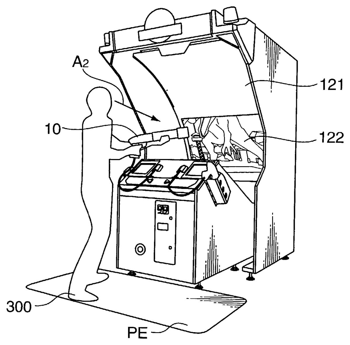
As shown inFIG. 1AandFIG. 1B, the player300standing in the play area PE of a prescribed area set in front of the game machine operates the gun unit10and virtually shoots the dinosaur as the game character displayed in the projected images122,123on the screen121. The dinosaur having a 3D shape and which moves and shifts with the elapse in time within the game space (virtual three-dimensional space) is displayed in the projected image122as shown inFIG. 2when existing afar as an image captured from the virtual viewpoint (which corresponds to the position of the reference viewpoint of the player300set in advance), and is displayed in the projected image123as shown inFIG. 3or in the projected image122as shown inFIG. 4when nearby.
Particularly, with the present game machine, the displayed contents of the projected image122(FIG. 1A) displayed at the lower part of the screen121changes to the projected image123(FIG. 1B) in accordance with the virtual viewpoint moving within the game space and position of the dinosaur while shifting continuously toward the arrow A1, and, pursuant to this type of shifting of the projected image on the screen121, the visual line of the player300changes naturally from the lower part of the screen121to the upper part of the screen121(from the direction of arrow A2ofFIG. 1Ato the direction of arrow A3ofFIG. 1B).
Further, with the present game machine, it is envisioned that the dinosaur within the game space is to attack the player, and displayed on the upper part of the screen121is an image where the dinosaur is trying to bite the player on the play area PE from the state within the projected image123ofFIG. 3, and an image where the dinosaur is trying to kick (or whipping its tail against) the player is displayed on the lower part of the screen121from the state within the projected image122ofFIG. 4.
The player300may avoid these attacks by the dinosaur by moving to the left and right on the play area PE. When the player300who is shooting toward the head of the dinosaur as shown inFIG. 1Bmoves to the left and right (direction of arrow A4) on the play area as shown inFIG. 5upon sensing that the dinosaur will begin its attack, with the present game machine, this movement is detected, the coordinates are set such that the virtual player (virtual viewpoint) moves away from the dinosaur within the game space, and a projected image123showing the player300moving away from the dinosaur (the dinosaur moves outward toward the direction of arrow A5) is displayed.
Although the upper and lower parts of the enormous dinosaur approaching the virtual viewpoint are displayed on the upper and lower parts of the screen121inFIG. 3andFIG. 4, a flying dinosaur (pterosaur) afar from the virtual viewpoint may be displayed on the lower part of the screen121, the displayed contents thereof may be continuously changed and continuously shifted in accordance with the flying dinosaur with respect to the virtual viewpoint in order to display the flying dinosaur approaching the virtual viewpoint on the upper part of the screen121.
FIGS. 6 to 11will now be explained in this order regarding the structure of the present game machine for performing the overall operation described above.FIG. 6andFIG. 7are diagrams relating to the structure for projecting images and performing imaging with the gun unit10,FIG. 8andFIG. 9are diagrams relating to the structure of the light source unit (marker) which is the detection subject for detecting the muzzle16direction, andFIG. 10andFIG. 11are diagrams relating to the structure for protecting the rotation and the like of the mirror43.
The structure for projecting images is now explained.FIG. 6is a diagram showing the appearance of the present game machine, andFIG. 7is a typical cross section for explaining the shifting of the projected image on the screen121.
With the present game machine, as shown inFIG. 6, the projected image124projected from the projector31(FIG. 7) on the screen121retained with the screen retention table120shifts in the arrow A6direction, and the gun unit10and gun unit20are connected to the main body control unit100(explained later atFIG. 13) via the gun cable17. The projected image124contains a shooting target such as a dinosaur as described above, and the 1P player standing on the play area PE operates the gun unit10(or the 2P player operates the gun unit20) to virtually shoot the shooting target, and points are scored in accordance with the skill of shooting such as the shooting position and shooting timing.
The four player detection sensors51to54mounted on the front face of the base110are for detecting the movement of the 1P player when it is a one player game (or 1P player and 2P player when it is a two player game) in the left and right directions, and side plates125are provided for preventing the disturbance and the like upon detecting the muzzle direction (described later) with respect to the screen121and displaying images on the screen121.
Further, with the present game machine, music and the like is played in order to yield vigor, and a speaker (top)32, speaker (left)33and speaker (right)34for outputting sounds in the middle and high ranges, and a woofer speaker35for outputting sounds in the low ranges are provided in order to output such sounds during the game. The speaker (top)32and speaker (left)33form one pair and the speaker (top)32and speaker (right)34form one pair in order to playback in stereo sound.
A coin of a prescribed amount is inserted into the coin insertion slot38, the start button36is suitably pressed in accordance with the display on the screen121, and a one player game with only the 1P player or a two player game with both the 1P player and 2P player is selectively started.
The rectangular flat mirror43, as shown inFIG. 7, has a mirror axis45extending in the perpendicular direction in the diagram, and both ends of the mirror axis45are rotatably retained with the mirror retention member46. The rotation of the stepping motor41connected to the control unit described later is transmitted to the mirror with the timing belt44, and the projected image124shifts in the arrow A6direction on the screen by the mirror43being rotated in the direction of arrow A7.
The reference viewpoint set at a prescribed height and position at the front of the present game machine is associated with the virtual viewpoint within the game space, and it is envisioned that a player (of an average height) is able to view the screen121from this reference viewpoint position.
Next, explained is the structure for detecting the direction of the muzzle16. Preferably a color CCD camera6as the imaging means is mounted in forward orientation at a prescribed height and position at the left, right and center of the screen121shown inFIG. 7. The CCD camera6is directed in the direction of θ so as to at least include the muzzle position in the game of the gun unit10operated by the player, and adopted are those which have a prescribed visual field width (solid angle of the range shown with the chain line). It is preferable that the CCD camera6be built in the likes of a housing61for blocking light such that it will not receive the projected light from the projector31to the screen121.
FIG. 8is a diagram showing the structure of the gun unit10(similar with the gun unit20) as an example of the controller for accepting input operations from the player, andFIG. 9is a diagram showing an example of the mounting structure of the marker provided to the gun unit10for detecting the direction of the muzzle16with respect to the screen121.
The gun unit10, as shown inFIG. 8A, simulates a pump action gun, and has a trigger switch11as the micro switch that is turned on when the player pulls the trigger14in the direction of arrow A8, a pump trigger switch12as the micro switch that is turned on when the player slides the sliding unit15in the direction of arrow A9, and a marker13for detecting the point where the direction of the muzzle with respect to the screen121; that is, the direction of the muzzle16(visual line vector) intersects with the screen121. Signals from the trigger switch11and the pump trigger switch12are transmitted to the main body control unit100via the gun cable17, virtual shooting is designated by the trigger switch11being turned on, and the loading of a prescribed number of virtual bullets is designated to the gun unit10when the pump trigger switch12is turned on. When the marker13is not of a reflective type and is rather a self-illuminating type, a power source supply line is included in the gun cable.
As shown inFIG. 8B, the marker13mounted on the tip (marker mounting section) of the muzzle16of the gun unit10comprises a plate shaped substrate130, and, for example, LEDs131to135as the five dotted light sources for emitting prescribed colors having the same shape in the present embodiment are disposed on such plate surface in prescribed intervals, preferably in prescribed equal intervals in the vertical and horizontal directions. LEDs131to135are structured such that LED131is at the intersecting point position of the vertical and horizontal axes in the present embodiment, LEDs132and133are disposed in equal intervals in the vertical axis direction (LED131and LED132structure the first light source unit, LED132and LED133structure the second light source unit, and LED132is shared in the present embodiment), and LEDs134and135are disposed in equal intervals in the horizontal direction (LED131and LED134structure the third light source unit, LED134and LED135structure the fourth light source unit, and LED134is shared in the present embodiment). Mounting position information on the respective plate surfaces of LEDs131to135is, for example, stored in the likes of a ROM105of the main body control unit100shown inFIG. 12as position information with LED131as the reference. It is preferable that an illuminator capable of emitting infrared light be used as the LEDs131to135for preventing the erroneous detection by outside light. In a mode where the LED131is not shared and respectively divided in the vertical and horizontal directions, the number of LEDs will become six. LED132and LED134do not have to be shared either. Further, the color of the substrate130is adopted upon being colored to a color capable of being identified with the CCD camera6against the luminescent color of the LED, and, as described later, enabled is the measurement of the vertical and horizontal dimension of the substrate130; that is, dimension of the distance to the CCD camera6. Needless to say, a CCD camera capable of only receiving infrared light may also be used.
FIG. 8Cis a diagram showing an example of the image imaged with the CCD camera6and incorporated in the image memory, and, as illustrated therein, obtained are images of the luminescent spots131ato135acorresponding to the LEDs131to135. Moreover, as shown in the diagram, the image is imaged in an oval as shown with the chain line around the substrate; that is, in a posture facing the oblique direction, and it is evident that the luminescent spots131ato135aare compress and mapped in the left and right directions.
FIG. 9is a diagram showing an example of the mounting structure of the dotted light source. The LEDs131to135as the dotted light source are mounted, for example, in an upright posture on the substrate130of a prescribed size to which is mounted an LED illuminating drive circuit or the like. Pores130afrom which the illumination unit6of the LEDs131to135is exposed are provided at prescribed positions on the substrate130.
When providing a description with LED131as the example, the pore130ais formed in a conical shape (cone shape) broadening toward the front of the of the substrate130, and the light emitted from the respective LEDs may be irradiated at a broad angle. A stud nut130chaving a prescribed height is welded at two places at the left and right sides of the thin metal plate130b, or established by pressurization (to the pore not shown formed on the thin metal plate130c), and the mounting plate130dand the thin metal plate130bare integrally formed by mounting a mounting plate130don these nuts130cand tightening this with a bolt130efrom the opposite face. The thin metal plate130bto the bolt130eform the LED supporting unit. A pore130fis further formed at both end positions of the thin metal plate130b, and, although not shown, a triangular screw penetrates the cone shaped pore formed on the substrate130in order to integrally form the substrate130and muzzle16by tightening the bolt via the LED supporting unit.
Next, explained is the structure for protecting the rotation and the like of the mirror43.FIG. 10is a typical cross section showing the acrylic plate142established for protecting the projection of the image form the projector31, andFIG. 11is a diagram showing the structure of the acrylic plate retention member141(FIG. 11A) and the acrylic plate142(FIG. 11B).
The acrylic plate142(FIG. 11B) established so as to cover the mirror43, projector31and the like in a state of where the end thereof is passing through the acrylic plate guide groove143(FIG. 11A), as shown inFIG. 10, transmits the images from the projector31, and protects the inside which houses the likes of the mirror43and projector31from outside sources. Further, when the real image is projected on the upper part of the screen121, an inclination of roughly 10° is provided from the horizontal direction such that the virtual image is connected to the outside of the screen121with the light reflected from the likes of the acrylic plate143and mirror43.
The control of the present game machine structured as above is now explained with reference toFIGS. 12onward.FIG. 12is a block diagram showing the hardware structure of the control unit of the present game machine, andFIG. 13is a flowchart showing the procedure of the shooting game processing (shooting video game program) executed with the game control unit (CPU)103.
As shown inFIG. 12, connected to the (game control unit103of the) main body control unit100set within the base110(FIG. 6) are the aforementioned CCD camera6; trigger switches11,21; pump trigger switches12,22; player detection sensors51to54; start button36; projector31; stepping motor41; speakers32to35; coin switch37for detecting the insertion of the coin from the coin insertion slot38; and position sensor42for determining the rotational reference position of the mirror with the semicircular plate mounted on the mirror axis (upon turning on the power), and the display position of the projected image124on the screen121(FIG. 7) is continuously designated by the game control unit103designating the rotation angle from the rotational reference position.
Provided to the main body control unit100are a ROM105storing the program, image data and sound data for the shooting video game processing described later; a RAM106for temporarily storing the program read from the ROM105and data used in the program; a game control unit103for controlling the overall progress of the game based on the program loaded on the RAM106; a drawing control unit (image drawing processor)101for writing image data corresponding to the projected image of the projector31in the frame buffer102while performing processing unique to the image such as polygon drawing and texture mapping in accordance with the coordinates of the object having a 3D shape within the game space; and a sound control unit (sound control processor)104comprising an ADPCM sound source for reproducing sounds from the sound data.
With the shooting video game processing to be executed at the game control unit103, as shown inFIG. 13, if the coin insertion is not detected with the coin switch37(NO at ST2), demo image data is read and a demo screen is displayed (ST1).
When the insertion of the coin is detected (YES at ST2), the start screen is displayed (ST3), (and when the pressing of the start button36is further detected) the game start processing is executed (ST5) and the game is started after other game data is read (ST4) which characterizes the image data and sound data differing per stage, and the attack or movement of the enemy character (foregoing dinosaur or other shooting targets) and the movement of the player.
With the present game machine, similar to conventional hand-to-hand combat game machines, a virtual life of the player is set and reduced in accordance with the time limit of the game and the attack by the enemy character, and the game is ended when the time is up during the game progress (YES at ST6) or when the life runs out (NO at ST7), and a screen indicated game over is displayed (ST13). If time still remains (NO at ST6) and the life still remains (YES at ST7), the game is continued at the game processing main body (ST8, to be described in detail later with reference toFIG. 15and the like).
When a stage is cleared (YES at ST9) by defeating the enormous dinosaur shown inFIGS. 2 to 4, and the cleared stage is not the final stage (NO at ST10), processing from ST4is repeated for the new stage.
When the cleared stage is the final stage (YES at ST10), the markers13,23are turned off thereafter (ST11), the ending screen and game over screen are displayed (ST12, ST13), and the routine returns to the processing of ST1.
FIG. 14is a block diagram showing the structure of the principal parts of the game processing unit400(part of the shooting video game program) for performing the processing with the game processing main body at ST8ofFIG. 13, andFIG. 15is a flowchart showing the detailed procedure of the processing with the game processing main body at ST8.FIG. 16andFIG. 17are diagrams for explaining the detection of the position of the player300on the play area PE with the player detection sensors51to54(in a one player game with only 1P player).
As shown inFIG. 14, when taking the gun unit10as an example as the processing unit for performing processing in relation to the player (virtual viewpoint, or virtual player within the game space), the game processing unit400has a light-up processing unit400afor lighting the marker during the game; a muzzle direction detection unit401for detecting the position on the screen121to which the muzzle is facing based on the image captured with the CCD camera6; an I/O input unit402for inputting the on-state of the pump trigger switch12and trigger switch11and the detection status of the player detection sensors51to54; a bullet-loading processing unit403for processing the loading of a prescribed number of virtual bullets when the pump trigger switch12is turned on; a bullet position computation unit404for setting the coordinates so as to move the bullets in a direction according to the direction of the muzzle16from the vicinity of the virtual viewpoint within the game space when the trigger switch11is turned on; a viewpoint position shifting unit405for ordinarily shifting the virtual viewpoint within the game space (at a shifting width designated in advance) and shifting the virtual viewpoint so as to avoid the dinosaur when the player detection sensors51to54detect the movement of the player on the player area PE; and a collision judgment unit406for judging whether the virtual attack from the enemy hit the player.
Further, as the processing unit for performing processing relating to the enemy character, the game processing unit400has an enemy attack setting unit407for generating the attack to the player when the enemy character is sufficiently close to the player (using random numbers, etc.); an enemy movement processing unit408for moving the enemy character upon setting the enemy character coordinates so as to chase the player within the game space; and an enemy collision judgment unit409for judging whether the virtual attack from the player hit the enemy. The game processing unit400further has an image processing unit410for setting data which designates the drawing control unit101so as to draw based on the setting of the enemy character coordinates and rotating the stepping motor41in accordance with where to display the projected image of the projector31on the screen121, for example, whether to display the projected image on the upper part or lower part; and a sound processing unit411for setting data which designates the sound control unit104to selectively reproduce sounds (including music) according to the game progress.
With the game processing main body executed at the game processing unit400including each of the foregoing processing units, as shown inFIG. 15, light-up processing of the marker13is foremost conducted (ST80), the muzzle direction detection processing is then conducted with the muzzle direction detection unit401(ST81, described later in details with reference toFIG. 18and the like), and the response status of the pump trigger switch12, trigger switch11and player detection sensors51to54is obtained with the I/O input unit402(ST82).
If the pump trigger switch12is responding (YES at ST83), the bullets are virtually loaded at the bullet-loading processing unit403(ST84). If the trigger switch11is responding (YES at ST85), the coordinates representing the trajectory of the bullets within the game space are computed (ST86) in accordance with the direction of the muzzle16with respect to the screed detected with the muzzle direction detection unit401.
If the response state of the player detection sensors51to54is of a prescribed pattern showing the movement of the player300on the play area PE (YES at ST87), the avoidance movement of the virtual viewpoint is set with the viewpoint position shifting unit405(ST88), and, if the response status of the player detection sensors51to54is not of a prescribed pattern (NO at ST87), the normal movement of the virtual viewpoint is set (ST89).
In further detail, the player detection sensors51to54are range sensors for detecting the distance to the obstacle with supersonic waves or infrared rays, and turning on the signal when the distance to the obstacles is less than a prescribed distance (distance corresponding to the player300on the play area PE) (it is not necessary to measure the distance accurately). As shown inFIG. 16andFIG. 17, when it is detected that 1P player shifted from the reference position in front of the player detection sensor52on the inner left side to the front of the player detection sensor51on the outer left side during an ordinary case, the virtual viewpoint coordinates are set within the game space deeming that the player has moved around to the left side of the dinosaur.
Particularly, here, since the movement to the left side is detected with a combination of two player detection sensors, as shown inFIG. 17, it is possible to detect “a state where nobody is playing” and “a state of erroneously recognizing the gallery other than the player” in addition to the movement itself, and it is possible to detect the movement of the player with further accuracy.
Further, regarding the 1P player's movement to the right side (FIG. 16), when it is detected that the player moved to the front of the player detection sensor53on the inner right side (or the player detection sensor54on the outer right side), the virtual viewpoint coordinates are set within the game space deeming that the player has moved around to the right side of the dinosaur.
Moreover, the reference position may be moved to the front of the player detection sensor53on the inner right side. Here, when it is detected that the player moved to the front of the player detection sensor54on the outer right side, the virtual viewpoint coordinates may be set within the game space deeming that the player has moved around to the right side of the dinosaur, and when it is detected that the player moved to the front of the player detection sensor52on the inner left side (or the player detection sensor51on the outer left side), the virtual viewpoint coordinates may be set within the game space deeming that the player has moved around to the left side of the dinosaur.
When the collision judgment unit406judges that the attack from the enemy character hit the player (YES at ST90ofFIG. 15), the player's life is reduced, and the player's life gauge display (which represents the player's life value on the screen in a pole shape) is renewed (ST91).
When an attack from the enemy character to the player is generated in the enemy attack setting unit407(YES at ST92), coordinates within the game space of the respective portions are set (ST93) such that the attack against the player is generated from the portions which the enemy character generates attacks such as the mouth, arms, legs and tail. When the enemy character movement is set in the enemy movement processing unit408(YES at ST94), enemy character coordinates within the game space are moved (ST95). Next, when the enemy collision judgment unit409judges that the attack from the player hit the enemy character (YES at ST96), the enemy's life is reduced, and the enemy life gauge display is renewed (ST97).
It is possible to assume that one or two or more enemy characters exist in the game space, and while the target enemy character is being renewed, processing of ST92to ST97for all enemy characters is repeated (NO at ST98). When all processing of ST92to ST97for all enemy characters is completed (YES at ST98), image display processing with the image processing unit410(ST99) and the sound output processing with the sound processing unit411(ST100) are conducted, and the processing of the game processing main body returns to the beginning.
FIG. 18is a block diagram showing the structure of the principal parts of the muzzle direction detection unit401for performing the muzzle direction detection processing at ST81ofFIG. 15;FIG. 19is a flowchart showing the detailed procedure of the muzzle direction detection processing at ST81; andFIG. 20is a diagram showing the detailed procedure of the extraction processing of the dotted light source at ST815.
As shown inFIG. 18, the muzzle direction detection unit401has an image processing unit4011for repeatedly incorporating in prescribed cycles the CCD image (data per pixel is stored in a prescribed area on the RAM106) which is the picture image of the CCD camera6; a binary processing unit4012for binarizing data per imaged pixel as a prescribed threshold and storing this in a prescribed area on the RAM106as luminescent spot data, or performing binary processing after temporarily storing the same; a coordinate data extraction unit4013for extracting coordinate data in which the binarized luminescent spot data exists and performing prescribed data arrangement; a straight line judgment unit4014for successively selecting the combination of the three spots from the extracted luminescent spot data and judging whether such three spots exist on the straight line and whether they are of equal intervals; a vicinity judgment unit4015for judging whether another luminescent spot exists in the vicinity of a luminescent spot on one end with respect to the three spots existing on the straight line (main axis); a dotted light source specification unit4016for associating the luminescent spot and the dotted light source with the judgment of both judgment units; a normal line computation unit4017for computing the direction of the muzzle16of the gun unit10(normal line direction of the substrate130) from the position information of the associated luminescent spot and the dotted light source thereof; and an intersecting point (H, V) computation unit4018for computing the intersecting point (impact position) with the screen121of the computed normal line direction of the substrate130. The CCD image includes luminescent spots other than the LED; that is, noise, caused by infrared rays contained in the natural light and infrared rays contained in the fluorescent lights and discharge lamps. Therefore, the straight line judgment unit4014and the vicinity judgment unit4015endeavor to eliminate the noise by performing judgment processing for all combinations.
Here, the normal line computation unit4017and intersecting point (H, V) computation unit4018will be explained in further detail. The positions of the LEDs131to135of the marker when the substrate130is flat is Pa (0, 0), Pb (1, 0), Pc (2, 0), Pd (0, 1), Pe (0, 2), and when these are defined upon expanding to the three-dimensional space, the positions will become0a(0, 0, 0),0b(1, 0, 0),0c(2, 0, 0),0d(0, 1, 0),0e(0, 2, 0). Meanwhile, when these defined coordinates of the respective points are viewed from the CCD camera6(with the CCD camera6as the origin), the coordinates will be represented as a value enjoining three-dimensional matrix such as Ca (tx, ty, tz), Cb (tx+r00, ty+r01, tz+r02), Cc (tx+2×r00, ty+2×r01, tz+2×r02), Cd (tx+r10, ty+r11, tz+r12), Ce (tx+2×r10, ty+2×r11, tz+2×r12). Meanwhile, the dimension ratio ph, pv in the vertical and horizontal directions of the visual field of the CCD camera and the actual substrate130(may also be obtained from the imaging dimension of the substrate130with respect to the actual dimension) and the coordinates Ga (Ah, Av), Gb (Bh, Bv), Gc (Ch, Cv), Gd (Dh, Dv), Ge (Eh, Ev) of the respective points in the CCD image are all publicly known. Thus, variables tx, ty, tz, r00to r12can be computed from these publicly known data and the coordinates of the respective points viewed from the CDD camera6, and the components (r20, r21, r22) of the normal line direction of the substrate130are thereby determined. Moreover, the reason why the value contained in the two items of coordinates Cc and Ce was made to be double value against r00, r01, r02, r10, r11, r12; that is, to be in proportion is because the substrate130is represented as a plane (as a simulation). In reality, when considering that the substrate130is of a curved surface, a three-dimensional matrix should be defined in consideration of the curvature of such curved surface with respect to the respective coordinates. By conducting the foregoing computation, although there may be cases where either the LED131or LED133is near or undefined in the CCD camera6depending the direction of the muzzle16, it becomes possible to specify the direction by employing the dimension information of LED131, LED132, LED133and the dimension information of LED131, LED134, LED135; that is, by employing the relationship of the dimension when the muzzle16is in the correct position and the ratio thereof.
The intersecting point (H, V) on the screen121of the normal line of the substrate130is sought with (tx+tz·(r20/r22), ty+tz·(r21/r22)) from the obtained position of the marker13, normal line direction information (r20, r21, r22) of the substrate130, and surface position information of the screen with the preset (predefined) CCD camera6as the origin. Further, during this computation, since the position of the marker13has been computed, this position information may be adopted as necessary, and, for instance, a desired dynamic detection of the controller10becomes possible with continuous computation, and it will no longer be necessary to adopt the conventional structure such as the triangular ranging method.
Moreover, as described above, although LED131, LED132, LED133, LED131, LED134, LED135are not limited to being a fixed pitch, in this case also, they may be computed so as long as they have each pitch information. In addition, the game control unit103further has a trajectory computation unit for computing the trajectory of bullets flying within the game space from impact position on the screen121based on the information obtained with the intersecting point (H, V) computation unit4018and the information obtained with the normal line computation unit4017and the intersecting point (H, V) computation unit4018.
InFIG. 19, image (CCD) data is foremost incorporated by activating the CCD camera6under trigger conditions such as vertical synchronization (V-sync, V-blank) at a prescribed cycle, 1/60 seconds for example (ST811), and then the incorporated data is binarized with the binary processing unit4012in order to extract luminescent spots (ST812). Here, coordinates of the binary data to be treated as luminescent spots are incorporated, an identification symbol is added thereto (labeling), and appropriate grouping processing is performed (ST813) in a mode where the coordinate data exist dispersedly. Then, the rough specification of the luminescent spots is conducted (ST814) based on the position data of luminescent spots, group information, and shape information (prepared as necessary). Next, each luminescent spot specified at ST814is named A to E (ST815).
Thereafter, the coefficient of the dimension ratio ph, pv is multiplied against the position data of luminescent spots A to E (ST816). Next, coordinates tz of the z component are computed with the marker13of the CCD camera6as the origin regarding the coordinate data of luminescent spots A, B, C (ST817), x component tx, y component ty, r00, r01, r02are then computed from the camera coordinates tz (ST818), r10, r11, r12are thereafter computed based on the coordinate data of luminescent spots D, E and tx, ty, tz (ST819), and the normal line vector (r20, r21, r22) of the substrate130; that is, the intersecting point (H, V) of the gun unit13direction and the screen121is then computed as described above (ST820). When the computation is complete, the intersecting point (H, V) which is the computation result is forwarded to the CPU103side, and utilized in the collision judgment processing of the shooting against the enemy character (may also be considered for impact presentation) and the like. Moreover, in a case where a plurality of markers are lit up for a two player game, the intersecting point (H, V) of the other markers is similarly computed, and the suitable intersecting point data may be utilized.
FIG. 20is a detailed subroutine of ST815, and the existing luminescent spot positions are foremost structured (formed) into a graph composed of the vector and distance (ST831). The luminescent spot position data within the graph is organized in accordance with the foregoing grouping or in a somewhat sorted state, thereby facilitating the data analysis. Next, the vector is utilized to research whether the three luminescent spots are of a straight line relationship be operating the inner product of the adjacent two points for example (ST832). When a straight line relationship does not exist (NO at ST833), it is judged whether processing for all combinations has been completed (ST834), and the routine returns to ST832when in the middle, and skips to ST821when it has been completed. Meanwhile, if a straight line relationship exists at ST833, knowledge from the distance between the luminescent spots (arranged status) is confirmed; that is, whether the three spots on the main axis are aligned in approximately equal intervals is confirmed (ST835). If a combination of a substantially equal interval does not exist, the routine returns to ST832, and if it exists, the routine researches the luminescent spot in the vicinity of both ends of the three spots (distance in which the LED134structuring the marker is deemed to exist) (ST837). Here, if a luminescent spot does not exist in the vicinity (NO at ST838), the routine returns to ST832, and if it exists, the routine researches the relationship of the luminescent spot in the vicinity and the luminescent structuring the main axis, and the shape of the marker is estimated thereby (ST839). The reason such luminescent spot is treated as D depending on the conditions of the existence in the vicinity is because the relationship of the intersection and equal distance with the LED.A will not be established depending on the direction of the camera. Next, A, B, C, D are encoded from the positional relationship of the respective luminescent spots in order to determine the arrangement thereof (ST840).
According to the muzzle16direction detection processing as described above, to which part of the screen121the muzzle16is ultimately facing, and the virtual trajectory position of the bullets fired toward the target object from the muzzle16within the game space from a position on the screen may be computed with the characteristics of the positional relationship of the image of the marker within the CCD image.
FIG. 21is a block diagram showing the structure of the principal parts of the image processing unit for performing the image display processing at ST99ofFIG. 15, andFIG. 22is a flowchart showing the detailed procedure of the image display processing at ST99.
The image processing unit410for displaying images while performing such correction, as shown inFIG. 21, has a visual line elevation setting unit4101for setting the visual line elevation (angle inclining the visual line upward against the level surface) in accordance with the object position data421(data representing the position of the shooting target object within the game space); a mirror inclination control unit4102for designating the rotation angle of the mirror in accordance with the visual line elevation and controlling the stepping motor41; and an image generation indication unit4103for designating the generation of images to the drawing control unit101.
With the image display processing, as shown inFIG. 22, the visual line elevation is set with the visual line elevation setting unit4101(in accordance with the dinosaur position or the parts of the dinosaur which generate attacks during the approach) (ST991), the mirror rotation angle according to this visual line elevation is designated with the mirror inclination control unit4102(ST992), and the mirror43rotates as a result of the stepping motor41being controlled (ST993). Next, drawing of the image captured from the prescribed virtual viewpoint is indicated with the drawing control unit101against the set visual line elevation with the image generation indication unit4104(ST994), and this processing is returned to the beginning. In accordance with the indication of drawing, with the drawing control unit101, image data is generated upon operating data relating to polygons within the (three-dimensional) game space, this image data is written in the frame buffer102, and images are projected on the screen121in accordance with the image data on the frame buffer102.
FIG. 23is a diagram for explaining the rotation control of the mirrors corresponding respectively to the two areas in which one stage is divided with the first modified example of the shooting video game machine.
With the game machine in the present modified example, an area501corresponding to the first half of the first stage and an area502corresponding to the second half are assumed, and the player shoots small dinosaurs and flying dinosaurs (ordinary enemy characters) in the first half area501and shoots the foregoing enormous dinosaurs (enemy character corresponding to the boss character) in the second half area502. In the area501within the game space, the virtual player (virtual viewpoint) will move in the direction of arrow B1at a speed designated in advance. An enemy character appears when the virtual player passes through prescribed positions511to514, and the player virtually shoots at the display of such enemy character with the gun unit10. When the player detection sensors51to54respond, the player is made to move a relatively small distance to the left or right within the game space just enough to avoid the attack from the enemy character, and the mirror for determining the position of the projected image on the screen is rotated based on the data designated in advance.
In the area502within the game space, the player avoids the attack of the boss character522approaching the virtual player521within the game space by making the player detection sensors51to54respond and moving in the arrow B2or arrow B3direction, and the player shoots at the display of the boss character by operating the gun unit. The boss character522will move in the arrow B4or arrow B5direction so as to follow the moving virtual player521.
Here, the player is made to move a relatively large distance upon the response of the player detection sensors51to54(movement so as to move around the left or right side of the dinosaur, and the a different distance range such as 5 meters, 20 meters, etc. is set in accordance with the stage), and the mirror is rotated in accordance with the distance between the boss character and the virtual viewpoint as described above, or in accordance with the portion in the boss character is to make the attack.
With the game machine of the present modified example, since the distance of movement upon the player detection sensors51to54responding and the method of mirror rotation control is differed, the player is able to enjoy a shooting game abundant in changes and unwearying.
FIG. 24is a diagram for explaining the detection of the position of player300(during the two player game with 1P player and 2P player) with the player detection sensors51to54with the second modified example of the shooting video game machine.
With the game machine of the present modified example, during a two player game, the two virtual players within the game space share the same fate, and move in the same direction. When it is detected that 1P player (left side player) moved from the reference position in front of the player detection sensor52on the inner left side to the front of the player detection sensor52on the outer left side, this is deemed as the player moving around to the left side of the dinosaur, and the coordinates of the two virtual players are set within the game space. Moreover, when it is detected that 2P player (right side player) moved from the reference position in front of the player detection sensor53on the inner right side to the front of the player detection sensor54on the outer right side, this is deemed as the player moving around to the right side of the dinosaur, and the coordinates of the two virtual players are set within the game space.
With the shooting video game machine of the present modified example, since the coordinates of the virtual players are set in accordance with the movement of the two players, unique amusement in the game progress may be yielded upon the mutual cooperation of the players.
Here, the video game device, which is a modified mode of the foregoing shooting video game machine, is explained.
FIG. 25is an overall perspective view of the video game device. As shown inFIG. 25, the video game device comprises a console type game housing1000having a rectangular parallelepiped shape for example, a display unit1101is disposed at the front upper part thereof, a CCD camera1102is provided to the front lower part thereof, and, although not shown, a speaker1103(c.f.FIG. 27) for yielding sound effects is provided to a suitable position in the housing, and a start button1001(c.f.FIG. 27) for indicating game start is provided to the approximately center right or left, for example. The display unit1101is formed of a CRT, LCD or the like, and an image of a sports stadium including a tennis court1201for example is displayed thereon, and an opponent character1202is displayed on the opponent's court side. The player P to play the game upon standing in the play area PE prepared in front of the game housing1000will play the competition game upon holding the controller1300simulating a tennis racket. The CCD camera1102corresponds to the CCD camera6in the previous embodiments, and is set to at least include the visual field of the controller1300to be swung by the player positioned in the play area PE. The setup position of the CCD camera1102is not limited to the position shown inFIG. 26, and may be immediately above the display unit1102, or the left or right side; in other words, it will suffice so as long as the position is able to observe the changes in the direction of the face of the simulated net of the simulated tennis racket to be swung by the player. In some cases, the mounting position may be separate from the game housing1000, and, in such a case, it should be considered that the CCD camera1102is established on the game housing side from the relationship of signal processing. The purpose of this game is to repeat the motion of returning the tennis ball hit from the opponent back to the opponent's court via a game medium of a tennis ball (not shown inFIG. 26) with the opponent character (competition with the computer for example) within the game screen, and the game is played in accordance with the rules of a tennis game.
FIG. 26shows the front view of the controller1300simulating a tennis racket, and dotted light sources1301to1305such as LEDs structuring the light source unit are mounted to the face of the net portion (marker mounting section). The power source of LEDs may be supplied with a cable, or batteries may be built therein (inside the grip for instance). The dotted light sources1301to1303are disposed in equal intervals in the longitudinal direction, and the dotted light sources1304and1305are disposed in equal intervals in the width direction together with the dotted light source1301to be shared. Imaging of the controller1300with the CCD camera1102, the intersecting angle (direction) formed with the screen of the display unit1101of the net face of the controller1300, and the height and left/right positions with respect to the screen of the display unit1101are obtained by executing operational processing similar to the operation method in the previous embodiments. The CCD camera1102performs imaging operations at a prescribed cycle, 1/60 seconds for example, and the operational processing for seeking the intersecting angle as well as the height and left/right positions is repeated.
FIG. 27is a block diagram of the video game device. The present device comprises a CPU1400as the control unit, a ROM1501storing game program data, image data required in the game (each image data may be structured with objects as virtual three-dimensional objects structured from polygons), sound data and other fixed data (e.g., three-dimensional position information and the like of the display unit1101with the CCD camera1102as the origin), and a RAM1502for temporarily storing data under processing.
The CPU1400is for controlling the desired game progress by collectively or suitably reading necessary game program data or other data from the ROM1501, and comprises a controller position operation unit1401for computing the position of the controller; a controller direction operation unit1402for computing the direction of the controller; a collision judgment unit1403for judging the virtual collision of the ball character as the game medium and the controller1300; a return processing unit1404for computing the return direction and speed when the ball character is returned with the controller1300; an in/out judgment unit1405for judging whether the returned ball character is in the in area or out area of the opponent's court; an opponent character processing unit1406for performing the movement processing of the opponent character; a ball character processing unit1407for performing the positional computation of the ball character; a drawing processing unit1408for performing drawing processing to the display unit1101of the tennis court1201, opponent character1202and ball character; and an evaluation processing unit1409for managing the game score and victory/defeat.
The controller position operation unit1401is for computing the direction and position with respect to the screen of the display unit1101by executing an operational processing similar to the operation method in the previous embodiments from the position information of the dotted light sources1301to1305of the controller images with the CCD camera1102. The controller direction operation unit1402is for computing the direction of the flat face of the net portion of the controller1300with respect to the screen of the display unit1101by performing processing similar to the previous embodiments.
The collision judgment unit1403is for judging whether the ball character virtually hit the controller1300from the flight direction (virtual flight from the screen) of the ball character described later, and the position and direction information of the controller1300at the point when the ball character within the game image flies from within the virtual three-dimensional space and computationally coincides with the position on the screen of the display unit1101.
The return processing unit1404is for computing the flight path of the ball character returned by the player from the swing speed sought with the position and direction of the controller1300and two times worth of consecutive computed positional information of the controller1300computed successively when it is deemed by the collision judgment unit1403that the ball character virtually hit the net of the controller. The in/out judgment unit1405is for judging whether the ball character in which the flight path thereof is computed with the return processing unit1404landed on the inside or outside of the opponent's court.
The opponent character processing unit1406is for making the behavior of the opponent character existing within the game space and controlled with the CPU1400to follow the motion procedures by incorporating the ordinary motion in a tennis match into the game program, and produces the movement in the front/back/left/right directions within the opponent's court, serve motion, return motion and so on. The ball character processing unit1407is for performing the movement processing of the ball character moving to the screen side from the ball hitting motion of the opponent character, and to perform the movement control of the ball character virtually hit by the player, preferably in consideration of adding gravity, drive, cut, and other ball rotations.
The drawing processing unit1408is for displaying information annunciating the game progress such as the tennis court1201, opponent character1202, ball character, scores, acquired sets and so on upon employing the image data read from the ROM1501on the screen of the display unit1101in accordance with the game program and behavior of the controller1300. The evaluation processing unit1409is for executing the processing for determining the score and victory/defeat in accordance with the rules of a tennis match.
When simply explaining the operational procedure of this tennis game, after the game is started upon the start button1001being pushed, the game begins with the score at 0-0, and the serve motion by the opponent character1202is displayed. The flight patch of the ball character is computed based on the position of this serve motion within the virtual three-dimensional space and the direction and speed of the smash motion, and the movement of the ball character along such direction is displayed. The controller position operation unit1401and the controller direction operation unit1402compute the position and direction of the controller1300in prescribed cycles after the game is started, and judges whether the controller1300hit the ball character from the position, direction and swing speed of the controller1300at the time the ball character arrives at the screen. If it is a miss, air shot processing (minus evaluation processing) is executed, and if it is a hit, the return direction and speed of the ball character is computed upon executing dynamic computation. The flight path of the ball character within the virtual three-dimensional space is sought based on the computation described above, and the ball character is displayed on the screen. Whether the returned ball character landed within the opponent's court is judged, and minus evaluation is made if outside the court, and, if inside the court, judgment is made on whether the opponent character is able to return the ball character from the landing position of the ball character (equivalent to the distance between the landing point and the position of the opponent player) and the speed (also upon reflecting the drive, cut or other ball rotations). If it is returnable as a result of such judgment, the opponent character is made to operate for returning the ball character, and the flight computation of such ball character is further conducted. By repeating the foregoing operation, the score is renewed when either player misses the ball character. When either player wins 6 set game a prescribed number of times in accordance with tennis rules, the victory/defeat is determined, and the game is over.
Further, since both faces of the racket may be used for hitting a ball in tennis and the like, it is preferable that the dotted light sources1301to1305are mounted so as to be exposed on both sides of the net portion, such that the illuminated light is emitted to both faces. Here, since three dotted light sources1301to1303and1301,1304,1305are provided respectively in each axis, the front/back judgment will become undefined in cases where the racket is turned in the normal line direction of the racket face.
Therefore, as the structure of the controller1300, as shown inFIG. 26, although one prescribed color may be used (when using only one face), the net portion may be formed with plates having colors different from the dotted light sources on the front and back. Or, the illuminated color of the dotted light sources1301,1302,1303may be made the same (blue for example), and at least one among the dotted light sources1304or1305may be made a color (green for example) differing from the foregoing color. According to this structure, distinction of the front and back will be realized in addition to facilitating the specification processing of the dotted light sources within the picture image and the judgment of the axis side, and the processing speed will improve thereby. With the front and back distinction in this case, a green light source will rotate 90° from the blue color and imaged on the front face in the clockwise direction of the dotted light source1301for example, and this will be the reverse color relationship on the back face. Here, at least one on the specific same axis side other than the dotted light source1301may also be flash controlled. Or, the size and shape of the dotted light source may be made to differ from the others. As described above, the dotted light source for judging the front and back may be made to have a different light-emitting form than the other dotted light sources. Moreover, since the dotted light source for judging the front and back is shared with one of the dotted light sources1301to1305, the number of dotted light sources may be reduced in comparison to cases of separately providing such dotted light source.
Further, as shown inFIG. 28, a reverse T shape may be employed as the shape of the biaxial direction marker. Here, the illuminant color of the dotted light sources1311to1313is made the same color (green for example) in order to distinguish the front and back, and the illuminant color of the dotted light source1314is made to be a different color (red for example), and/or the illuminant color of the dotted light source1315is made to be a different color (blue for example). Thus, the color of at least the dotted light source1314or the dotted light source1315needs to be a different color (green in this example). Since the controller1310is simulating a racket, the front and back thereof is switched by the racket being swung around the axis parallel to the axis of the dotted light sources1311to1313, and it will suffice to change the color of the dotted light source on the side sandwiching the rotational axis.
Similarly,FIGS. 29A,29B and29C are diagrams show a simulated table tennis racket used as the controller1320when the video game device it used for playing a table tennis game. Since both sides of the table tennis racket may be used to hit the ball, it is desirable that dotted light sources capable of recognizing the front and back be disposed. In other words, as shown inFIG. 29A,FIG. 29BandFIG. 29C, three dotted light sources1321to1323are disposed on the ball-hitting face of the racket on one side with respect to the grip axis and parallel to the axis, dotted light sources1324and1325are provided to the opposite side of the axis upon sharing the dotted light source1321, and light may therefore be emitted from either face upon exposing both the front and back sides. Moreover, by differing the illuminant color of the dotted light source1324or1325from the other dotted light sources, the recognition processing of the front and back may be simplified, and the rotational angle with respect to the rotational axis of the grip from the luminescent spot images corresponding to the dotted light sources1321and1324within the picture image; that is, the direction with respect to the screen of the display unit may be operated. In addition, the front and back judgment will also become possible with the imaging means recognizing a different color if the color of the ball-hitting face of the racket (ground color) is made to differ for the front and back.
Second Embodiment
The shooting video game machine pertaining to the second embodiment of the present invention is explained below.
With the shooting video game machine pertaining to the second embodiment, the setup positions of the CCD camera6and the marker13are switched in the shooting video game machine pertaining to the first embodiment. In other words, the marker13is disposed on the shooting video game machine main body side (screen121), and the CCD camera6is disposed on the gun unit10. Thus, the description ofFIGS. 1 to 5in the first embodiment corresponds to the second embodiment. This shooting video game machine is now explained below.
FIG. 30andFIG. 31are diagrams relating to the structure for projecting images,FIG. 32andFIG. 33are diagrams relating to the structure for detecting the direction of the muzzle216, andFIG. 34is a diagram showing the mode of markers26to29and the structural diagram for mounting such markers to the screen.
The structure for projecting images is not explained.FIG. 30is a diagram showing, the appearance of the present game machine, andFIG. 31is a typical cross section for explaining the shifting of the projected image on the screen2121.
With the present game machine, as shown inFIG. 30, the projected image2124projected from the projector231(FIG. 31) on the screen2121retained with the screen retention table2120shifts in the arrow A26direction, and the gun unit210and gun unit220are connected to the main body control unit2100(explained later atFIG. 35) via the gun cable217. The projected image2124contains a shooting target such as a dinosaur as described above, and the 1P player standing on the play area PE operates the gun unit210(or the 2P player operates the gun unit220) to virtually shoot the shooting target, and points are scored in accordance with the skill of shooting such as the shooting position and shooting timing.
The four player detection sensors251to254mounted on the front face of the base2110are for detecting the movement of the 1P player when it is a one player game (or 1P player and 2P player when it is a two player game) in the left and right directions, and side plates2125are provided for preventing the disturbance and the like upon detecting the muzzle direction (described later) with respect to the screen2121and displaying images on the screen2121.
Further, with the present game machine, music and the like is played in order to yield vigor, and a speaker (top)232, speaker (left)233and speaker (right)234for outputting sounds in the middle and high ranges, and a woofer speaker235for outputting sounds in the low ranges are provided in order to output such sounds during the game. The speaker (top)232and speaker (left)233form one pair and the speaker (top)232and speaker (right)234form one pair in order to playback in stereo sound.
A coin of a prescribed amount is inserted into the coin insertion slot238, the start button236is suitably pressed in accordance with the display on the screen2121, and a one player game with only the 1P player or a two player game with both the 1P player and 2P player is selectively started.
The rectangular flat mirror243, as shown inFIG. 31, has a mirror axis245extending in the perpendicular direction in the diagram, and both ends of the mirror axis245are rotatably retained with the mirror retention member246. The rotation of the stepping motor241connected to the control unit described later is transmitted to the mirror with the timing belt244, and the projected image2124shifts in the arrow A26direction on the screen by the mirror243being rotated in the direction of arrow A27.
The reference viewpoint set at a prescribed height and position at the front of the present game machine is associated with the virtual viewpoint within the game space, and it is envisioned that a player (of an average height) is able to view the screen2121from this reference viewpoint position.
Next, explained is the structure for detecting the direction of the muzzle216.FIG. 32is a diagram showing the structure of the gun unit210(similar with the gun unit220) as an example of the controller for accepting input operations from the player, andFIG. 33is a diagram showing an example of the arrangement of the markers26to29for detecting the direction of the muzzle216with respect to the screen2121together with the CCD camera213in the gun unit210.
FIG. 33Ais a diagram showing the front view of the screen2121extended on the level plane, andFIG. 33Bis a diagram showing the side view of the screen2121provided in the present game machine. InFIG. 33, the markers26to29have the same shape, and a prescribed number (four in this embodiment) is disposed in the vertical direction, preferably in equal intervals, at the center position of the surface of the screen2121. The mounting position information for each of the markers26to29with respect to the screen2121is stored in the likes of a ROM2105of the main body control unit2100shown inFIG. 35. The arrangement position of the markers may be set in accordance with the shape of the screen, and, in the present embodiment, markers are provided in the vicinity of the top or bottom of the screen2121and at two locations in which the space therebetween is divided in thirds. Moreover, the number of markers may be suitably set in accordance with the size of the screen and visual field angle of the CCD camera213.
The gun unit210, as shown inFIG. 32, simulates a pump action gun, and has a trigger switch211as the micro switch that is turned on when the player pulls the trigger214in the direction of arrow A28, a pump trigger switch212as the micro switch that is turned on when the player slides the sliding unit215in the direction of arrow A29, and a CCD camera213having a visual field angle capable of imaging at least one, up to two in this embodiment, among the markers26to29for detecting the point where the direction of the muzzle with respect to the screen2121; that is, the direction of the muzzle216(visual line vector) intersects with the screen2121.
Signals from the trigger switch211, the pump trigger switch212and the CCD camera213are transmitted to the main body control unit2100via the gun cable217, virtual shooting is designated by the trigger switch211being turned on, and the loading of a prescribed number of virtual bullets is designated to the gun unit210when the pump trigger switch212is turned on.
Depending on the visual field2431of the CCD camera213, as shown inFIG. 33A, only a part of the screen2121may be imaged, and, as further shown inFIG. 33B, the distance between the CCD camera213(within the gun unit210) and the screen2121is changed in accordance with the player's operation during the game progress, and the size of the portion of the screen2121to fit within the visual field2431of the CCD camera213will change.
With the present game machine, detected are the arrangement of the image and the rotational angle information of the one marker illuminating with the mounting position information of the markers26to29(as described later) within the CCD image corresponding to the visual field2431, and detected is which part of the screen2121the player is facing the muzzle216, and the intersecting point thereof.
FIG. 34Ashows the form of the markers, andFIG. 34BandFIG. 34Cshow the mounting structure to the screen2121. Since the markers26to29have the same shape, marker26will be explained here. Four LEDs26A to26D are adopted in the marker26as the spot light source (illuminator) for illuminating infrared light for preventing erroneous detection by outside light. LED26A to LED26C are disposed on a straight line (main axis) in prescribed equal intervals, LED26has the same interval as the foregoing prescribed interval from LED26A, and provided on the line (sub axis) intersecting with the main axis. Since the shape of the markers form an L shape, the expression “L shape” will be used in the second embodiment when referring to the marker shape. The mounting position information of the marker26is prescribed and stored for each LED, and the LED26A is the reference position in the present embodiment.
The interval between LED26A to LED26D is preferably equal, and it not limited thereto. The disposition of LED26D at a position of intersecting with the sequence of LED26A to LED26C is preferably form the computational processing perspective to be performed based on the marker position and rotation angle within the picture image described later.
FIG. 34Bshows the mounting structure of the LED26D. The LED26D is mounted, for example, in an upright posture on the substrate611of a prescribed size to which is mounted an LED illuminating drive circuit or the like. Pores2121afrom which the illumination unit of the LED26D is exposed are provided at prescribed positions on the substrate611. The pore2121ais formed in a conical shape (cone shape) broadening toward the front face of the screen2121, and the light emitted from the LED26D may be irradiated at a broad angle. A stud nut613having a prescribed height is welded at two places at the left and right sides of the thin metal plate612, or established by pressurization (to the pore not shown formed on the thin metal plate612), and the substrate611and the thin metal plate612are integrally formed by tightening a bolt614from the opposite face upon mounting the substrate611on this nut613. A pore612ais further formed at both end positions of the thin metal plate612, and, although not shown, a triangular screw penetrates the cone shaped pore2121bcorresponding to the screen2121in order to integrally form the screen2121and the thin metal plate612by tightening the bolt.
FIG. 34Cshows the mounting structure of LEDs26A to26C, and this is basically the same mounting structure as with LED26D. In other words, the LEDs26A to26C are mounted, for example, in an upright posture on the substrate621of a prescribed size. Three pores2121afrom which the illumination unit of the LEDs26A to26C is exposed are provided at prescribed positions on the screen2121. The pores2121aare formed in a conical shape broadening toward the front face of the screen2121, and the light emitted from the LEDs26A to26C may be irradiated at a broad angle. Moreover, the thin metal plate622is of a size capable of containing LEDs26A to26C (three LED worth), a stud nut623having a prescribed height is welded at three places, or established by pressurization (to the pore not shown formed on the thin metal plate622), and the substrate621and the thin metal plate622are integrally formed by tightening a bolt from the opposite face upon mounting the substrate621on this nut623. Pores622aare further formed at suitable positions of the thin metal plate622, and, although not shown, a triangular screw penetrates the cone shaped pore2121bcorresponding to the screen2121in order to integrally form the screen2121and the thin metal plate622by tightening the bolt.
Further, the structure for protecting the rotation and the like of the mirror243is the same as the first embodiment shown inFIG. 10andFIG. 11, and the explanation thereof is omitted.
The control of the present game machine structured as above is now explained.FIG. 35is a block diagram showing the hardware structure of the control unit of the present game machine, andFIG. 36is a flowchart showing the procedure of the shooting game processing (shooting video game program) executed with the game control unit (CPU)2103.
As shown inFIG. 35, connected to the (game control unit2103of the) main body control unit2100set within the base2110(FIG. 30) are the aforementioned trigger switches211,221; pump trigger switches212,222; CCD cameras213,223; markers26to29; player detection sensors251to254; start button236; projector231; stepping motor241; speakers232to235; coin switch237for detecting the insertion of the coin from the coin insertion slot238; and position sensor242for determining the rotational reference position of the mirror243with the semicircular plate mounted on the mirror axis (upon turning on the power), and the display position of the projected image2124on the screen2121(FIG. 31) is continuously designated by the game control unit2103designating the rotation angle from the rotational reference position.
Provided to the main body control unit2100are a ROM2105storing the program, image data and sound data for the shooting video game processing described later; a RAM2106for temporarily storing the program read from the ROM2105and data used in the program; a game control unit2103for controlling the overall progress of the game based on the program loaded on the RAM2106; a drawing control unit (image drawing processor)2101for writing image data corresponding to the projected image of the projector231in the frame buffer2102while performing processing unique to the image such as polygon drawing and texture mapping in accordance with the coordinates of the object having a 3D shape within the game space; and a sound control unit (sound control processor)2104comprising an ADPCM sound source for reproducing sounds from the sound data.
With the shooting video game processing to be executed at the game control unit2103, as shown inFIG. 36, if the coin insertion is not detected with the coin switch237(NO at ST22), demo image data is read and a demo screen is displayed (ST1). When the insertion of the coin is detected (YES at ST22), the start screen is displayed (ST23), (and when the pressing of the start button236is further detected) the game start processing is executed (ST25) and the game is started after other game data is read (ST24) which characterizes the image data and sound data differing per stage, and the attack or movement of the enemy character (foregoing dinosaur or other shooting targets) and the movement of the player.
With the present game machine, similar to conventional hand-to-hand combat game machines, a virtual life of the player is set and reduced in accordance with the time limit of the game and the attack by the enemy character, and the game is ended when the time is up during the game progress (YES at ST26) or when the life runs out (NO at ST27), and a screen indicated game over is displayed ST213). If time still remains (NO at ST26) and the life still remains (YES at ST27), the game is continued at the game processing main body (ST28, to be described in detail later with reference toFIG. 38and the like).
When a stage is cleared (YES at ST29) by defeating the enormous dinosaur shown inFIGS. 2 to 4of the first embodiment, and the cleared stage is not the final stage (NO at ST210), processing from ST24is repeated for the new stage. When the cleared stage is the final stage (YES at ST210), the markers26to29are turned off thereafter (ST211), the ending screen and game over screen are displayed (ST212, ST213), and the routine returns to the processing of ST21.
FIG. 37is a block diagram showing the structure of the principal parts of the game processing unit2400(part of the shooting video game program) for performing the processing with the game processing main body at ST28ofFIG. 36, andFIG. 38is a flowchart showing the detailed procedure of the processing with the game processing main body at ST28.FIG. 39andFIG. 40are diagrams for explaining the detection of the position of the player on the play area PE2(corresponds to player300ofFIG. 1andFIG. 5in the first embodiment) with the player detection sensors251to254(in a one player game with only 1P player).
As shown inFIG. 37, as the processing unit for performing processing in relation to the player (virtual viewpoint, or virtual player within the game space), the game processing unit2400has a light-up processing unit2400afor lighting one of the markers26to29corresponding to the screen2121position to which the projected image is displayed; a muzzle direction detection unit2401for detecting the position on the screen2121to which the muzzle is facing based on the image captured with the CCD camera213; an I/O input unit2402for inputting the on-state of the pump trigger switch212and trigger switch211and the detection status of the player detection sensors251to254; a bullet-loading processing unit2403for processing the loading of a prescribed number of virtual bullets when the pump trigger switch212is turned on; a bullet position computation unit2404for setting the coordinates so as to move the bullets in a direction according to the direction of the muzzle216from the vicinity of the virtual viewpoint within the game space when the trigger switch211is turned on; a viewpoint position shifting unit2405for ordinarily shifting the virtual viewpoint within the game space (at a shifting width designated in advance) and shifting the virtual viewpoint so as to avoid the dinosaur when the player detection sensors251to254detect the movement of the player on the player area PE2; and a collision judgment unit2406for judging whether the virtual attack from the enemy hit the player.
Further, as the processing unit for performing processing relating to the enemy character, the game processing unit2400has an enemy attack setting unit2407for generating the attack to the player when the enemy character is sufficiently close to the player (using random numbers, etc.); an enemy movement processing unit2408for moving the enemy character upon setting the enemy character coordinates so as to chase the player within the game space; and an enemy collision judgment unit2409for judging whether the virtual attack from the player hit the enemy. The game processing unit400further has an image processing unit2410for setting data which designates the drawing control unit2101so as to draw based on the setting of the enemy character coordinates and rotating the stepping motor241in accordance with where to display the projected image of the projector231on the screen2121, for example, whether to display the projected image on the upper part or lower part; and a sound processing unit2411for setting data which designates the sound control unit2104to selectively reproduce sounds (including music) according to the game progress.
With the game processing main body executed at the game processing unit2400including each of the foregoing processing units, as shown inFIG. 38, light-up processing of one of the markers26to29corresponding to the position on the screen2121to which the projected image2124is displayed is foremost conducted (ST280), the muzzle direction detection processing is then conducted with the muzzle direction detection unit2401(ST281, described later in details with reference toFIG. 44and the like), and the response status of the pump trigger switch212, trigger switch211and player detection sensors251to254is obtained with the I/O input unit2402(ST282).
If the pump trigger switch212is responding (YES at ST283), the bullets are virtually loaded at the bullet-loading processing unit2403(ST284). If the trigger switch211is responding (YES at ST285), the coordinates representing the trajectory of the bullets within the game space are computed (ST286) in accordance with the direction of the muzzle216with respect to the screed detected with the muzzle direction detection unit2401.
If the response state of the player detection sensors251to254is of a prescribed pattern showing the movement of the player on the play area PE2(YES at ST287), the avoidance movement of the virtual viewpoint is set with the viewpoint position shifting unit2405(ST288), and, if the response status of the player detection sensors251to254is not of a prescribed pattern (NO at ST287), the normal movement of the virtual viewpoint is set (ST289).
In further detail, the player detection sensors251to254are range sensors for detecting the distance to the obstacle with supersonic waves or infrared rays, and turning on the signal when the distance to the obstacles is less than a prescribed distance (distance corresponding to the player on the play area PE2) (it is not necessary to measure the distance accurately). As shown inFIG. 39andFIG. 40, when it is detected that1P player shifted from the reference position in front of the player detection sensor252on the inner left side to the front of the player detection sensor251on the outer left side during an ordinary case, the virtual viewpoint coordinates are set within the game space deeming that the player has moved around to the left side of the dinosaur.
Particularly, here, since the movement to the left side is detected with a combination of two player detection sensors, as shown inFIG. 40, it is possible to detect “a state where nobody is playing” and “a state of erroneously recognizing the gallery other than the player” in addition to the movement itself, and it is possible to detect the movement of the player with further accuracy.
Further, regarding the 1P player's movement to the right side (FIG. 39), when it is detected that the player moved to the front of the player detection sensor253on the inner right side (or the player detection sensor254on the outer right side), the virtual viewpoint coordinates are set within the game space deeming that the player has moved around to the right side of the dinosaur.
Moreover, the reference position may be moved to the front of the player detection sensor253on the inner right side. Here, when it is detected that the player moved to the front of the player detection sensor254on the outer right side, the virtual viewpoint coordinates may be set within the game space deeming that the player has moved around to the right side of the dinosaur, and when it is detected that the player moved to the front of the player detection sensor252on the inner left side (or the player detection sensor251on the outer left side), the virtual viewpoint coordinates may be set within the game space deeming that the player has moved around to the left side of the dinosaur.
When the collision judgment unit2406judges that the attack from the enemy character hit the player (YES at ST290ofFIG. 38), the player's life is reduced, and the player's life gauge display (which represents the player's life value on the screen in a pole shape) is renewed (ST291).
When an attack from the enemy character to the player is generated in the enemy attack setting unit2407(YES at ST292), coordinates within the game space of the respective portions are set (ST293) such that the attack against the player is generated from the portions which the enemy character generates attacks such as the mouth, arms, legs and tail. When the enemy character movement is set in the enemy movement processing unit2408(YES at ST294), enemy character coordinates within the game space are moved (ST295). Next, when the enemy collision judgment unit2409judges that the attack from the player hit the enemy character (YES at ST296), the enemy's life is reduced, and the enemy life gauge display is renewed (ST297).
It is possible to assume that one or two or more enemy characters exist in the game space, and while the target enemy character is being renewed, processing of ST292to ST297for all enemy characters is repeated (NO at ST298). When all processing of ST292to ST297for all enemy characters is completed (YES at ST298), image display processing with the image processing unit2410(ST299) and the sound output processing with the sound processing unit2411(ST2100) are conducted, and the processing of the game processing main body returns to the beginning.
FIG. 41is a block diagram showing the principal parts of the marker light-up processing unit2400a(part of the shooting video game program) for performing the marker light-up processing at ST280ofFIG. 38. The marker light-up processing unit2400ahas a projected image position judgment unit24001for receiving the position information of the screen2121to which the projected image2124is displayed from the image processing unit for performing drawing processing and judging the current projected position; a corresponding marker determination unit24002for specifying (determining) a marker as described later among the markers contained in the projected range from this projected position information and the predetermined position information of the markers26to29; and a corresponding marker light-up indication unit24003for performing the light-up indication to the four LEDs structuring the determined corresponding marker. Further, in a state where the display range of the projected image contains two markers, the marker closer to the center of the display range of the projected image will be selected, and when the two markers are roughly the same distance from the center, the marker corresponding to the shifting direction of the projected image on the screen is selected (that is, position information from the image processing unit2410is stored over several occasions, and comparison is made with the present position information so as to decide the marker facing the center).
FIG. 42is a block diagram showing the structure of the principal parts of the muzzle direction detection unit2401for performing the muzzle direction detection processing at ST281ofFIG. 38;FIG. 43is a flowchart showing the detailed procedure of the muzzle direction detection processing at ST281; andFIG. 44is a diagram showing the detailed procedure of the extraction processing of the “L frame” at ST2815.
As shown inFIG. 42, the muzzle direction detection unit2401has an image processing unit24011for repeatedly incorporating in prescribed cycles the CCD image (data per pixel is stored in a prescribed area on the RAM2106) which is the picture image of the CCD camera213; a binary processing unit24012for binarizing data per imaged pixel as a prescribed threshold and storing this in a prescribed area on the RAM2106as luminescent spot data, or performing binary processing after temporarily storing the same; a coordinate data extraction unit24013for extracting coordinate data in which the binarized luminescent spot data exists and performing prescribed data arrangement; a straight line judgment unit24014for successively selecting the combination of the three spots from the extracted luminescent spot data and judging whether such three spots exist on the straight line and whether they are of equal intervals; a vicinity judgment unit24015for judging whether another luminescent spot exists in the vicinity of a luminescent spot on one end with respect to the three spots existing on the straight line (main axis); an L frame specification unit24016for specifying the “L frame” with the judgment of both judgment units; a normal line computation unit24017for computing the direction of the camera from the specified L frame; that is, the normal line vector; and an intersecting point (H, V) computation unit24018for computing the intersecting point (impact position) with the screen2121of the computed normal line direction of the substrate2130. The CCD image includes luminescent spots other than the LED; that is, noise, caused by infrared rays contained in the natural light and infrared rays contained in the fluorescent lights and discharge lamps. Therefore, the straight line judgment unit4014and the vicinity judgment unit24015endeavor to eliminate the noise by performing judgment processing for all combinations.
Here, the normal line computation unit24017and intersecting point (H, V) computation unit24018will be explained in further detail. The positions of the LED.A to D of the marker when the screen2121is flat is A2(0, 0), B2(1, 0), C2(2, 0), D2(0, 1), and when these are defined upon expanding to the three-dimensional space, the positions will become 0a (0, 0, 0), 0b (1, 0, 0), 0c (2, 0, 0), 0d (0, 1, 0) or 0d (0, −1, 0). Meanwhile, when these defined coordinates of the respective points are viewed from the CCD camera13, the coordinates will be represented as a value enjoining three-dimensional matrix such as Ca (tx2, ty2, tz2), Cb (tx2+r200, ty2+r201, tz2+r202), Cc (tx2+2×r200, ty2+2×r201, tz2+2×r202), Cd (tx2+r210, ty2+r211, tz2+r212). Meanwhile, the dimension ratio ph, pv in the vertical and horizontal directions of the visual field of the CCD camera213and the actual screen2121and the coordinates LED.A2(A2h, A2v), LED.B2(B2h, B2v), LED.C2(C2h, C2v), LED.D2(D2h, D2v) of the respective points in the CCD image are all publicly known. Thus, variables tx2, ty2, tz2, r200to r212can be computed from these publicly known data and the coordinates of the respective points viewed from the CDD camera213, and the elements of the normal line vector of the CCD camera213are thereby determined. Moreover, the reason why the value contained in the two items of coordinates Cc was made to be double value against r200, r201, r202; that is, to be in proportion is because the screen is represented as a plane (as a simulation). In reality, when considering that the screen2121is of a curved surface, a three-dimensional matrix should be defined in consideration of the curvature of such curved surface against the respective coordinates. Then, from the elements of the obtained visual line vector, for example, the visual line vector det and the intersecting point (H, V) may be sought with det=r200×r211−r201×r210, H=(r211×(−tx)−r201×(−ty))×det, V=(−r210×tx−r200×(−ty))×det.
Moreover, as described above, although LED26A, LED26B, LED26C are not limited to being a fixed pitch, in this case also, they may be computed so as long as they have each pitch information. In addition, the game control unit2103further has a trajectory computation unit for computing the trajectory of bullets flying within the game space from impact position on the screen2121based on the information obtained with the intersecting point (H, V) computation unit24018and the information obtained with the normal line computation unit24017and the intersecting point (H, V) computation unit24018.
InFIG. 43, image (CCD) data is foremost incorporated by activating the CCD camera213under trigger conditions such as vertical synchronization (V-sync, V-blank) at a prescribed cycle, 1/60 seconds for example (ST2811), and then the incorporated data is binarized with the binary processing unit24012in order to extract luminescent spots (ST2812). Here, coordinates of the binary data to be treated as luminescent spots are incorporated, an identification symbol is added thereto (labeling), and appropriate grouping processing is performed (ST2813) in a mode where the coordinate data exist dispersedly. Then, the rough specification of the luminescent spots is conducted (ST2814) based on the position data of luminescent spots, group information, and shape information (prepared as necessary). Next, the luminescent spot group structuring the “L frame” is extracted from the luminescent position, and is encoded as A, B, C, D based on the arrangement status of the extracted luminescent spots (e.g., corresponds to LED26A,26B,26C,26D with the marker26) (ST2815).
Thereafter, the coefficient corresponding to the imaged range with respect to the screen2121of the CCD camera213is multiplied to LED. A to D with one of the markers26to29(ST2816). In the present embodiment, as described above, the distance from the CCD camera is successively differed (becoming farther) from the upper part to the lower part of the screen21, and, by multiplying a coefficient in accordance with the ratio of such difference in distance, the distance and correspondence (ratio) of the CCD image and on the actual screen2121is unified. Next, coordinates tz2of the z component are computed with the “L frame” of the CCD camera213as the origin regarding the coordinate data of LED. A, B, C (ST2817), x component tx2, y component ty2, r200, r201, r202are then computed from the camera coordinates tz2(ST2818), r210,2r11, r212are thereafter computed based on the LED. D coordinate data tx2, ty2, tz2(ST2819), and the intersecting point (H, V) of the cameral visual line vector when deeming the “L frame” to be flat is computed from tx2, ty2, tz2, r200, r201, r202, r210, r211, r212(ST2820). When the computation is complete, the intersecting point (H, V) which is the computation result is forwarded to the CPU2103side, and utilized in the collision judgment processing of the shooting against the enemy character (may also be considered for impact presentation) and the like. Moreover, in a case where a plurality of markers are lit up for a two player game, the intersecting point (H, V) of the remaining “L frames” is similarly computed, and the suitable intersecting point data may be utilized.
FIG. 44is a detailed subroutine of ST2815, and the existing luminescent spot positions are foremost structured (formed) into a graph composed of the vector and distance (ST2831). The luminescent spot position data within the graph is organized in accordance with the foregoing grouping or in a somewhat sorted state, thereby facilitating the data analysis. Next, the vector is utilized to research whether the three luminescent spots are of a straight line relationship be operating the inner product of the adjacent two points for example (ST2832). When a straight line relationship does not exist (NO at ST2833), it is judged whether processing for all combinations has been completed (ST2834), and the routine returns to ST2832when in the middle, and skips to ST2821when it has been completed. Meanwhile, if a straight line relationship exists at ST2833, knowledge from the distance between the luminescent spots (arranged status) is confirmed; that is, whether the three spots on the main axis are aligned in approximately equal intervals is confirmed (ST2835). If a combination of a substantially equal interval does not exist, the routine returns to ST2832, and if it exists, the routine researches the luminescent spot in the vicinity of both ends of the three spots (distance in which the LED. D structuring the L frame is deemed to exist) (ST2837). Here, if a luminescent spot does not exist in the vicinity (NO at ST2838), the routine returns to ST2832, and if it exists, the routine researches the relationship of the luminescent spot in the vicinity and the luminescent structuring the main axis, and the shape of the “L frame” is estimated thereby (ST2839). The reason such luminescent spot is treated as LED. D depending on the conditions of the existence in the vicinity is because the relationship of the intersection and equal distance with the LED.A will not be established depending on the direction of the camera. Next, A, B, C, D are encoded from the positional relationship of the respective luminescent spots in order to determine the arrangement thereof (ST2840).
According to the muzzle direction detection processing as described above, to which part of the screen2121the muzzle216is facing; that is, the position on the screen corresponding to the center of the CCD image, and the virtual trajectory position of the bullets fired toward the target object from the muzzle216within the game space from a position on the screen may be computed with the characteristics of the positional relationship of the image of the marker within the CCD image.
FIG. 45is a block diagram showing the structure of the principal parts of the image processing unit for performing the image display processing at ST299ofFIG. 40, andFIG. 46is a flowchart showing the detailed procedure of the image display processing at ST299.
Moreover,FIGS. 47A and 47Bare diagrams showing the display of an image corrected with the present game machine,FIGS. 48A and 48Bare diagrams showing the display of an ordinary image, andFIGS. 49A,49B and49C are diagrams for explaining the image correction parameter set in the present game machine.
When an ordinary image is projected from the projector231(FIG. 31) as shown inFIG. 48A, the player will view the image as shown inFIG. 48Bsince the distance from the reference viewpoint of the player on the play area PE2in front of the present game machine will differ between the upper part and lower part of the projected image2124due to the curvature of the screen2121.
With the present game machine, the image projected from the projector231is corrected prior to the projection as shown inFIG. 47A, and the player will view an undistorted image as shown inFIG. 47B. Further, since there is a difference in the distance from the reference point to the upper part and lower part of the projected image2124when the projected image2124is to be displayed at the lower part of the screen2121(corresponds to the solid line inFIG. 31) and when it is to be displayed at the upper part of the screen2121(corresponds to the dotted line inFIG. 31), the degree of correction will vary in accordance with the rotation angle of the mirror.
In the present image display processing, the image containing the display target having a 3D shape within the game space captured with a virtual camera (virtual viewpoint) having a rectangular visual field is corrected such that the lower end of the image is inclined to approach the virtual camera in accordance with the rotation angle of the mirror, and the corrected image is projected on the projector231.
The image processing unit2410for displaying images while performing such correction, as shown inFIG. 45, has a visual line elevation setting unit24101for setting the visual line elevation (angle inclining the visual line upward against the level surface, EYE_R ofFIG. 49described later) in accordance with the object position data2421(data representing the position of the shooting target object within the game space); a mirror inclination control unit24102for designating the rotation angle of the mirror in accordance with the visual line elevation and controlling the stepping motor241; and an image generation indication unit24103for referring to the image correction table2422(table associating the inclination angle CAM_R of the virtual camera, angle CAM_FT for designating the upper end of the image, angle CAM_FB for designating the lower end of the image with the visual line elevation EYE_R), reading and setting the image correction parameter corresponding to the visual line elevation, and designating the generation of images to the drawing control unit2101.
In reality, with the procedure shown inFIGS. 49A,49B and49C below, the inclination angle CAM_R of the virtual camera, angle CAM_FT for designating the upper end of the image, and angle CAM_FB for designating the lower end of the image may be designated from the visual line elevation EYE_R, and the association thereof is stored in the image correction table2422.
With the present game machine, a gaze envisioned position VIEW_P is set in accordance with the distance between the player and dinosaur, and the portion of the dinosaur which will generate an attack against the player during approach. As shown inFIG. 49A, in accordance with this gaze envisioned position VIEW_P, visual line elevation EYE_R as the angle of the straight line q0and the level plane (reference line) is set forth from the virtual viewpoint position EYE_P.
Next, as shown inFIG. 49B, in consideration of the position, inclination angle and projection angle of the projector231, and the position of the mirror243, the mirror rotation angle MIRROR_R is set forth such that the field angle EYE_FU to the upper part and the field angle EYE_FD to the lower part of the virtual camera become equal centered around the visual line elevation EYE_R in order to seek the upper end SCREEN_U and the lower end SCREEN_D of the projected image. (The virtual camera has a rectangular imaging range, and the upper end SCREEN_U and lower end SCREEN_D correspond to the field angle of the vertical direction of the virtual camera. The field angle in the lateral direction may be suitably sought from the distance from the EYE_P to the SCREEN_D and the width of the projected image.)
As shown inFIG. 49C, the intersecting point of the straight line q3passing through the projected image upper end SCREEN_U and the projected image lower end SCREEN_D and the perpendicular line q4from the virtual viewpoint position EYE_P to this straight line q3is sought as CAM_VP, and the angle (elevation) between the straight line q4and the level plane is set as the inclination angle CAM_R of the virtual camera. In addition, the angle between the straight line q4and the straight line q1, for prescribing the upper end position of the projected image is set as CAM_FT, and the angle between the straight line q1, and the straight line q2for prescribing (together with the CAM_FT) the lower end position of the projected image is set as CAM_FB.
According to the foregoing procedures, the virtual camera inclination angles CAM_R, CAM_FT, CAM_FB as image correction parameters are computed in accordance with the visual line elevation EYE_P (or the mirror rotation angle MIRROR_R set in accordance therewith) set during the progress of the game. Here, although the computed and partially adjusted CAM_R, CAM_FT, CAM_FB are associated in accordance with the visual line elevation EYE_R at the image correction table2422, these correction parameters may also be associated with the mirror rotation angle MIRROR_R.
In the image display processing employing these image correction parameters, as shown inFIG. 46, the visual line elevation is set with the visual line elevation setting unit24101(in accordance with the dinosaur position with respect to the virtual viewpoint or the parts of the dinosaur which generate attacks during the approach) (ST2991), the mirror rotation angle according to this visual line elevation is designated with the mirror inclination control unit24102(ST2992), and the mirror243rotates as a result of the stepping motor241being controlled (ST2993).
Next, image correction parameters (CAM_R, CAM_FT, CAM_FB, etc.) are designated with respect to the set visual line elevation (ST2994), and drawing of the image captured from the prescribed virtual viewpoint is indicated with the drawing control unit101with respect to the set visual line elevation with the image generation indication unit24104(ST2995), and this processing is returned to the beginning. In accordance with the indication of drawing, with the drawing control unit2101, image data corresponding to the 2D image inclined with respect to the visual line EYE_R is generated upon operating data relating to polygons within the (three-dimensional) game space, this image data is written in the frame buffer2102, and images are projected on the screen2121in accordance with the image data on the frame buffer2102.
According to the present image display processing, the image is suitable corrected in accordance with the position of the portion to be displayed on the screen having a curvature in the upward and downward directions, and the player is thereby able to enjoy a shooting video game while viewing an undistorted image.
The overall structure of the foregoing shooting video game machine and the advantages yielded from the structure thereof may be summarized as follows.
The present shooting video game machine enables the player to play the game while displaying images captured from a virtual viewpoint (virtual camera) in which the player's reference viewpoint position corresponds to the position in the game space. With the present game machine, a mirror is rotated so as to shift the image projected from the projector via the mirror at least in the upward and downward directions in correspondence with the direction of the virtual viewpoint at a portion within the screen continuously curved from the lower part of the approximate front of the reference viewpoint position to the upper part of the approximately top of the reference viewpoint position.
According to the present game machine, since the player's visual line will shift from top to bottom pursuant to the game progress, the player will be able to enjoy a novel game not available conventionally, and this can be realized with a simple structure. Further, since the screen is curved inward in a conical shape, the projection distance is maintained approximately constant, and the size and focus of the projected image can be maintained approximately constant.
Particularly, the screen may be made to curve such that the distance from the reference viewpoint position to the upper part becomes shorter than the distance from the reference viewpoint position to the lower part. According to this structured, the player will feel that the image on the upper part of the screen is approaching him/her, and a unique sense of tension may be yielded.
Further, the player virtually shoots with a gun unit the dinosaur displayed on the screen and corresponding to the size of the screen when it is nearby, and the parts such as the mouth, arms and legs of the dinosaur to virtually attack the player are displayed on the screen. Thus, the player is able to enjoy a shooting game which effectively yields a novel and unique sense of nervousness.
Moreover, since the mirror may be rotated such that a flying dinosaur (or a non-flying dinosaur) afar from the virtual viewpoint is displayed on the lower part of the screen and a flying dinosaur (or the upper part of the non-flying dinosaur) close to the virtual viewpoint is displayed on the upper part of the screen. Thereby, the flying dinosaur (or a non-flying dinosaur) approaching the player from afar may be represented with much vigor and perspective.
With the present game machine, since the acrylic plate for protecting the mirror rotation and the like is inclined and provided such that the virtual image is transmitted toward outside the screen when the real image is projected on the upper part of the screen, the player will not be distracted with the virtual image needlessly appearing on the screen.
In addition, when the player detection sensor becomes a prescribed detection state, the virtual viewpoints are moved so as to surround the periphery of the dinosaur within the game space, and the player's movement to the left and right may be conveyed within the game space naturally, and the amusement of the game will be enhanced thereby.
Further, particularly in relation to the detection of the muzzle direction, the structure and effect of the foregoing video game machine may be summarized as follows.
With the present shooting video game machine, the input corresponding to the shooting of the dinosaur displayed on the screen is conducted with the operation of the trigger in the gun unit, the CCD image of the imaged range corresponding to a part of the screen is generated with the CCD camera in the vicinity of the muzzle of the gun unit, and, in the least, when the trigger is pulled, the image of one marker among the plurality of markers disposed on the screen so as to hold a prescribed positional relationship is identified within the generated CCD image, and the shooting position on the screen corresponding to the approximate center of the imaged range is computed from the image position and rotation angle of the marker.
According to the present game machine, since the shooting position is computed upon identifying which part of the screen is being imaged from the image position and angle relationship of the marker in the CCD image, the direction of the gun unit can be detected smoothly with respect to the screen (which does not fit within the CCD image).
The detection of the gun unit direction is performed with respect to the screen curved inward and having a conical shape, an image to be the target of shooting is displayed at a portion of the top or bottom of the screen, and the image is shifted upward or downward in accordance with the direction of the virtual viewpoint. Thus, realized is a shooting game abundant in amusement and vigor.
Further, particularly in relation to the correction of images, the structure and effect of the foregoing shooting video game machine may be summarized as follows.
The present shooting video game machine enables the player to play the game while displaying images captured from a virtual viewpoint in which the player's reference viewpoint position corresponds to the position in the game space. With the present game machine, a mirror is rotated so as to shift the image projected from the projector via the mirror at least in the upward and downward directions in correspondence with the direction of the virtual viewpoint at a portion within the screen continuously curved from the lower part of the approximate front of the reference viewpoint position to the upper part of the approximately top of the reference viewpoint position. Further, the approximately vertical image that may be captured with the virtual viewpoint is corrected to become an image that may be obtain with a larger inclination the farther it is shifted upward on the screen when the lower side approaches the virtual viewpoint.
Particularly, this inclination angle may be made to be the same angle as the rotation angle of the projected image on the screen.
According to the present game machine, since appropriate correction is conducted in accordance with the mirror rotation, the image projected on the screen will not be distorted when viewed by the player.
Moreover, by setting an image correction parameter for designating the virtual camera rotation in accordance with the mirror rotation (or the visual line elevation set during the game progress) to the image drawing processor, the effective correction of images may be realized with a simple control.
A modified example of the shooting video game machine pertaining to the second embodiment is described below.
FIG. 50is a diagram for explaining the rotation control of the mirrors corresponding respectively to the two areas in which one stage is divided with the first modified example of the shooting video game machine.
In this game machine of the modified example, an area2501corresponding to the first half of the first stage and an area2502corresponding to the second half are assumed, and the player shoots small dinosaurs and flying dinosaurs (ordinary enemy characters) in the first half area2501and shoots the foregoing enormous dinosaurs (enemy character corresponding to the boss character) in the second half area2502.
In the area2501within the game space, the virtual player (virtual viewpoint) will move in the direction of arrow B21at a speed designated in advance. An enemy character appears when the virtual player passes through prescribed positions2511to2514, and the player virtually shoots at the display of such enemy character with the gun unit210. When the player detection sensors251to254respond, the player is made to move a relatively small distance to the left or right within the game space just enough to avoid the attack from the enemy character, and the mirror for determining the position of the projected image on the screen is rotated based on the data designated in advance.
In the area2502within the game space, the player avoids the attack of the boss character2522approaching the virtual player2521within the game space by making the player detection sensors251to254respond and moving in the arrow B22or arrow B23direction, and the player shoots at the display of the boss character by operating the gun unit. The boss character2522will move in the arrow B24or arrow B25direction so as to follow the moving virtual player2521.
Here, the player is made to move a relatively large distance upon the response of the player detection sensors251to254(movement so as to move around the left or right side of the dinosaur, and the a different distance range such as 5 meters, 20 meters, etc. is set in accordance with the stage), and the mirror is rotated in accordance with the distance between the boss character and the virtual viewpoint as described above, or in accordance with the portion in the boss character is to make the attack.
With the game machine of the present modified example, since the distance of movement upon the player detection sensors251to254responding and the method of mirror rotation control is differed, the player is able to enjoy a shooting game abundant in changes and unwearying.
FIG. 51is a diagram for explaining the detection of the position of player (during the two player game with 1P player and 2P player) with the player detection sensors251to254with the second modified example of the shooting video game machine.
With the game machine of the present modified example, during a two player game, the two virtual players within the game space share the same fate, and move in the same direction. When it is detected that 1P player (left side player) moved from the reference position in front of the player detection sensor252on the inner left side to the front of the player detection sensor252on the outer left side, this is deemed as the player moving around to the left side of the dinosaur, and the coordinates of the two virtual players are set within the game space. Moreover, when it is detected that 2P player (right side player) moved from the reference position in front of the player detection sensor253on the inner right side to the front of the player detection sensor254on the outer right side, this is deemed as the player moving around to the right side of the dinosaur, and the coordinates of the two virtual players are set within the game space.
With the shooting video game machine of the present modified example, since the coordinates of the virtual players are set in accordance with the movement of the two players, unique amusement in the game progress may be yielded upon the mutual cooperation of the players.
FIG. 52is a diagram shown the image correction parameter set in the shooting video game machine of the third modified example.
With the game machine of the present modification, SCREEN_U′ is set on the extension of q1, shown inFIG. 49C, and CAM_VP is set forth on the straight line q5passing through SCREEN_D and SCREEN_U′, CAM_R will become even smaller. By suitably adjusting the size of CAM_R to make CAM_R smaller or larger as described above, a natural image matching the player's reference viewpoint position may be generated, and an image yielding further vigor may be generated.
In addition to each of the foregoing embodiments, the present invention may be adopted in the following modified examples.
(1) With the shooting video game machine in each of the foregoing embodiments, images from the projector are projected on the screen upon being reflected with a mirror. Nevertheless, without using a mirror, images from the projector may be directly displayed on the screen upon changing the inclination angle of the projector, and it could be said that this offers an even simpler structure.
(2) Although each of the foregoing embodiments showed examples employed in a shooting game machine, the present invention is not limited thereto, and, for example, may assist in the bi-directional information communication by designating the subject on the screen with images (including text images). Notwithstanding the image display surface, this may also be employed in a mode of designating the desired position of the face of the area to become the designation. Here, in addition to being employed as a simulated gun, the controller may be adopted in other modes in accordance with the purpose thereof.
(3) The screen of the display unit displaying images is not limited to a projection screen, and may be employed in various display faces; for instance, television monitors, liquid crystal monitors, monitor screens of personal computers and so on. Further, in addition to the designation of the screen position and the like, this may also be employed in the operational designation of other various devices and equipment. For example, when employed in an operation button of a device, remote operational designation becomes possible by orienting such direction as the drive designation of the operation member.
(4) The dimensions and size of the marker are irrelevant in the present invention. A marker of various sizes may be adopted in consideration of the size of the controller to be employed. Moreover, the shape and form of the marker are not limited to an aggregate of dotted bodies, and may be of a pole shape. In the case of such pole shape, a processing execution unit for specifying the position of both ends thereof will further become necessary. In other words, the pole shape (continuity) is recognized from the picture image, and the position data (address within image memory) may be specified by detecting both sides thereof.
In addition, particularly, the dimension data of the respective dotted light sources (LEDs) of the marker is not considered. In other words, if the luminescent spot distance data of the picture image (or the interval data of the LEDs when the CCD camera213is at a reference position) with the CCD camera6when the controller10is at a reference position is previously stored as reference data, computation processing will be enabled in the subsequent measurements with the comparison with the reference data. Minute fluorescent tubes may be employed as the pole shaped body, and various objects may be adopted in the case of a reflector. Further, the mode may use both a dotted body and a pole shaped body. With respect to the marker (or an L frame), a marker (or L frame) may be formed by taking two pole shaped bodies each with a prescribed dimension, preferably the same dimension, and making the mutual ends thereof coincide or adjacent and disposing them to be in an intersecting direction, and disposing at least one dotted body as an extension of the other end of such one pole shaped body a prescribed distance apart. With the foregoing case, in a mode where two pole shaped bodies are disposed such that the mutual one ends are made to be adjacent; that is, apart from each other in a prescribed distance, the dotted body is not necessarily required. The recognizable position of the pole shaped body is the end and flection thereof, and is extracted from the picture image imaged with the CCD camera6(or CCD camera213). Moreover, when a color CCD is used as the CCD camera6(or CCD camera213) in a case where two pole shaped bodies are disposed such that the mutual one ends thereof are made to coincide, if a pole shaped body which emits a different color in the middle as the pole shaped body of one of the axes is connected and adopted, the four points of the two ends, the flection and the portion having differing luminescent colors may be recognized, which is effective as the marker (L frame).
(5) The marker (or L frame) shown in the foregoing embodiments is not influenced by the shape or size of the game screen or display screen, and versatility is high since there is only one analyzing method.
(6) In each of the foregoing embodiments, although an LED was employed as the illuminator as the light source, a reflector capable of reflecting the incident light from the front may be adopted instead. This structure offers a mode in which the likes of an illuminator (mounted at a prescribed position or on the controller10and screen212, respectively) reflects the light from the front of the controller10(or the screen2121) to which a reflector is provided, and the light reflected (emitted) from the reflector is received with the imaging means. Thereby, since it is no longer necessary to directly mount an illuminator to the controller10(or the screen2121), the structure becomes simple and the versatility high. Preferably, the shape of the reflector is of a semicircle or the like capable of generating reflected light at a desired width. When employing this in a controller, the movable range of the controller is not restricted needlessly, and the operability of the controller may be improved thereby. The structure may also extend the reflection range by generating a diffused reflection with the surface processing with respect to the reflective surface.
(7) The light source (illuminator, reflector) is not limited to an infrared light, and light of a desired color may be employed. For example, the color may be R (red), G (green) or B (blue), and may also be of another color. When using three markers, in addition to using markers with different colors, when a color CCD capable of receiving light of the respective colors is used as the CCD camera, the disposition of the respective markers may be recognized. As a result, individual light-up control as described in the present embodiment will no longer be necessary, and there is an advantage in that the light may always be turned on. Needless to say, it is not necessary to simultaneously use three colors worth, and markers of desired colors may be adopted in accordance with the use thereof.
(8) Further, although various shapes for markers may be considered, those basically containing the element of dotted light source is included in the concept of dotted light source.
(9) Moreover, in each of the foregoing embodiments, although the facilitation of computation was sought by intersecting the vertical and horizontal axes (one axis and other axis), this is not limited such intersection, and a desired intersecting angle may be set in accordance with the type of controller10(or screen2121).
(10) With the shooting video game machine pertaining to each of the foregoing embodiments, although two player detection sensors were provided to the left and right, one each or three or more may also be provided. Upon advancing to the next stage after clearing the respective stages, when a player is to select one route among a plurality of routes (having different settings of the dinosaur or background) set in advance, the selection may be input with these player detection sensors.
(11) Further, regarding the avoidance movement with the player detection sensor, in addition to the movement to the left and right, the movement may be to duck below, or the lower right oblique direction or lower left oblique direction. This is because the player will not be able to avoid the attack by moving left and right when the attack of the enemy character is of a movement where the arm or tail is whipped in the lateral direction. For example, if the player detection sensor on the left outer side is turned on, the movement may be automatically switched in accordance with the scene such that the attack is avoided by ducking below.
(12) When the screen of the shooting video game machine of each of the foregoing embodiments is extended to the upper part of the player on the play area and disposed so as to cover the player, the player will be of a posture of looking up at the image when viewing the image on the upper part, and this will yield a further feeling of tension. In addition to the curvature portion, a straight line portion may be included in the screen.
(13) Moreover, although the inclination angle of the acrylic plate of the shooting video game machine of each of the foregoing embodiments was set to roughly 10°, this may be suitably adjusted such that the virtual image is projected outside the screen in accordance with the position of the mirror, projector and screen.
(14) With the shooting video game machine of the second embodiment, although the mirror rotation angle with respect to the visual line elevation was associated in advance upon displaying images and the image correction parameter was stored in advance, the parameters may be successively operated according to the procedure shown inFIG. 46. In addition, the whole or a part of the screen to which the image subject to correction is to be projected may incline upward or downward or curve or incline left and right or obliquely, or be made of a semicircle shape. Additionally, upon projecting to the overall screen curving (up/down, left/right, or in a semicircle), the overall screen may be divided in several areas and correction may be conducted as described above in accordance with the position of the respective areas. Further, a front screen and at least two screens inclining obliquely (when viewed from the player) may be disposed left/right or up/down so as to surround the player, and correction as described above may be conducted to the display of the two screens inclining obliquely upon continuously displaying on these three screens.
(15) Further, with the shooting video game machine of each of the foregoing embodiments, although only a portion of the dinosaur to make the attack was partially displayed upon approaching the virtual viewpoint, a location to which the player should pay attention during the game progress may be displayed while facing the direction of the virtual viewpoint within the game space.
(16) Moreover, with the shooting video game machine of each of the foregoing embodiments, although the mirror axis for rotating the mirror was set to be a single axis in order to shift the projected image in the upward and downward directions on the screen, for example, two mirror axes may be provided in order to shift the projected image in the upward/downward as well as the leftward/rightward directions on the screen.
(17) As shown in each of the foregoing embodiments, provided is a highly versatile orientation detection device enabling two-player games and the simultaneous computation of directions even in cases where there are a plurality of controllers.
(18) Since the structure is such that analysis is conducted with a three-dimensional matrix, this may be sufficiently employed in a mode of the controller shifting in a three-dimensional space. Thus, the applicable range may be broadened.
(19) With the second embodiment, although four markers26to29were disposed on the screen2121, the disposition of one or two markers will suffice depending on the screen size and visual field of the CCD camera213, and it is not necessary to dispose them in equal spacing.
(20) Two types of L-shaped markers having a mirror surface relationship (vertical axis or horizontal axis) may be adopted as the marker capable of being employed in the second embodiment. Here, since these are individually distinguishable; that is, since it is possible to distinguish the arrangement position, individual light-up control as in the present embodiment is no longer required. In addition, in a mode where the rotational range of the controller is 180° or less, four-types of L frames having a mirror surface relationship with respect to the vertical axis and a mirror surface relationship with respect to the horizontal axis may be employed, and, since these are individually distinguishable; that is, since it is possible to distinguish the arrangement position, individual light-up control as in the present embodiment is no longer required at all. In other words, enabled is a mode where the disposition of orientation detection markers of different types (2 types or 4 types) having a mode in which the other axis with respect to the one axis of the biaxial direction includes mutually reverse axis information on the target area surface (screen, etc.) with a prescribed positional relationship. According to this, by employing differing orientation detection markers having a common basic form (in which the main axis and sub axis intersect), processing for individually identifying the same type of markers upon using the same will no longer be necessary.
Further, as another arrangement mode of markers, when providing an example with the arrangement of the present embodiment (four locations in the vertical direction of the left, right and center of the screen), two types of L frames or markers (among the foregoing four types) having a mirror surface relationship with respect to the vertical axis may also be disposed at a symmetrical position on the left and right side of the screen. In addition, since the two rows worth of markers adjacent in the upward and downward direction are mutually different types of markers, light-up control may be performed with three combination units; namely, the combination of the first row and second row, the combination of the second row and third row, and the combination of the third row and fourth row. Similarly, this may be employed in cases when the three types of L frames or the four types of L frames of mutually different types are disposed adjacently in unit of the number of types of L frames.
(21) The markers are not limited to fixed types. For example, in the present embodiment, one slit is provided in the vertical direction of the screen2121, markers are disposed so as to sandwich this slit, guide rails for sliding the markers along the slit are provided, and the markers are structured to be shiftable in the vertical direction while managing the position vertically with a drive means such as a motor. Thus, if the motor is driven so as to follow the position of the projected image, a single marker will realize the four markers in the present embodiment, and this may be treated as though existing in more numerous positions. Thus, the number of markers used may be reduced.
(22) In the second embodiment, although the projected image was drawn on the front face of the screen2121, a mode is also possible to draw the game image in which the image from the projector is projected on both the front and back faces depending on the shape of the screen. Here, in order to concurrently use the markers on both the front and back faces of the screen and enable the imaging with the CCD camera, for example, markers comprising the respective LEDs may be integrally mounted, or individual LEDs may be preferably mounted on the entire face through the pores penetrating the radial thickness of the screen, and light from the light-emitting unit of the LED may be structured so as to be capable of emitting to both the front and back faces of the screen (this is the same in the case of a reflector, and, for example, this may be mounted within the radial thickness such that the reflective surface exposes half of the spherical member on both sides. According to this structure, a game may be played upon using both the front and back faces of the screen, and, for instance, the image from the front of the dinosaur will be displayed on the front face and the image from the rear of the dinosaur will be displayed when moving toward the back face of the screen. Thus, provided is a highly amusing game with realism. In addition, since the markers will be of the three shapes having a mirror surface relationship with respect to the vertical axis with the front face and back face of the screen, the front or back of the screen may be automatically detected merely be recognizing the image from the CCD camera, and it is not necessary to additionally provide a human body sensor for detecting the circular movement of the player.
(23) Moreover, although various shapes for markers may be considered, those basically containing the element of dotted light source is included in the concept of dotted light source.
In summary, the present invention was devised in view of the foregoing problems, and the object thereof is to provide an orientation marker capable of remotely measuring the movement, particularly the orientation, of a controller having a simple structure, which may be employed in a more sophisticated game, and which is highly versatile; an orientation detection device for remotely measuring the orientation (posture) of the controller with such orientation detection marker; and a video game device employing the above.
In order to achieve the foregoing object, the orientation detection marker according to the present invention is provided in either one of the device main body and a controller for performing input operations as being pointed to a screen of a display unit provided to the device main body for displaying images, for detecting the orientation of the controller with respect to the screen, and which supplies information for computing said orientation to a picture image generated by imaging means provided in the other of the device main body and the controller, wherein said orientation detection marker comprises a light source having a mode including biaxial direction information.
According to the foregoing structure, a picture image is generated with the imaging means provided to the device main body side and one of the controllers. An image of the orientation detection markers is contained in the picture image. Since the orientation detection marker includes biaxial direction information, in addition to the position information of the controller, and (rotation) inclination centered around the axis of orientation of the controller; that is, rotation angle information is also included in the picture image. Thus, the orientation of the controller with respect to the screen may be computed from this position information and rotation angle information.
Further, it is preferable that the two axes are orthogonal to each other. According to this, the computation will become simplified since it is no longer necessary to employ a trigonometric function for positional computation. According to the invention with the above features, the computation will become simplified since it is no longer necessary to employ a trigonometric function for positional computation and a positional information can be directly obtained thus the calculation can be simplified.
Moreover, it is preferable that the light source is formed of a plurality of dotted light sources. According to this, the orientation detection marker may be made simply and inexpensively by structuring it from a dotted light source capable of identifying biaxial direction information.
According to the invention with the above feature, the orientation detection marker may be made simply and inexpensively by structuring it from a dotted light source capable of identifying biaxial direction information and the positional information can be directly obtained, thus the calculation is made easy.
In addition, the light source may emit light of a specific color. According to this, employed may be a marker capable of emitting light of a desired color in accordance with the purpose of use. According to the invention with the above features, employed may be a marker capable of emitting light of a desired color in accordance with the purpose of use.
Further, the plurality of dotted light sources may be formed by first and second light source units for specifying the first two points and second two points separated by a prescribed dimension on one axis and a third light source unit for specifying the third two points separated by a prescribed dimension on another axis being disposed on the orientation detection marker mounting section for mounting the orientation detection marker.
According to this, regarding the first to third light source units, since two will be in one axis direction and one will be in the other axis direction, specified are the respective positions of the first two points and the second two points of the first and second light source units from the image corresponding within the picture image as the mapping images with the imaging means and the position of the third two points of the third light source. Thus, detected will be the inclination of one axis in the axis periphery parallel at least to the other axis and the rotation angle against the reference angle position on the surface formed from the one axis and the other axis. If the arrangement position of the imaging means and the position of the device main body with respect to the imaging means is associated in advance, in the least, the orientation of the controller may be computed from the picture image. According to the invention claimed in claim5, specified are the respective positions of the first two points and the second two points of the first and second light source units and the position of the third two points of the third light source from the image corresponding within the picture image. Thus, detected will be the inclination of one axis in the axis periphery parallel at least to the other axis and the rotation angle with respect to the reference angle position on the surface formed from the one axis and the other axis, and the orientation of the controller will be computed thereby.
Moreover, the dimension between the first two points and the dimension between the second two points may be set to be equal. According to this, the computation for detecting the orientation of the controller may be simplified. According to the invention with the above features, the computation for detecting the orientation of the controller may be simplified.
In addition, the first and second light source units may share the inner two dotted light sources on the axis. According to this, since the dotted light sources are shared, the number of dotted light sources may be reduced by one. According to the invention with the above features, since the dotted light sources are shared, the number of dotted light sources may be reduced by one.
Further, one of the dotted light sources may be provided for common use at the intersecting point of the two axes. According to this, since the dotted light source of the intersecting point of the two axes is shared, the number of dotted light sources may be reduced by one. According to the invention with the above features, since the dotted light source of the intersecting point of the two axes is shared, the number of dotted light sources may be reduced by one.
Moreover, disposed may be a fourth light source unit for specifying the fourth two points separated by a prescribed dimension on the other axis. According to this, by adding the fourth two points, the inclination of the axis periphery parallel to one axis of the controller may also be detected. As a result, even when the controller is of a structure capable of being rotationally operated with respect to both the one axis and other axis; that is, in a synthesized direction, the foregoing orientation may be computed with respect to every orientation. According to the invention with the above features, by adding the fourth two points, the inclination of the axis periphery parallel to one axis of the controller may also be detected. As a result, even when the controller is of a structure capable of being rotationally operated with respect to both the one axis and other axis; that is, in a synthesized direction, the foregoing orientation may be computed with respect to every orientation.
In addition, the dimension between the third two points and the dimension between the fourth two points may be set to be equal. According to this, the computation is simplified since position information can be directly obtained. According to the invention with the above features, the computation is simplified since position information can be directly obtained.
Further, the third and fourth light source units may share the inner two dotted light sources on the axis. According to this, since the dotted light source is shared, the number of dotted light sources may be reduced by one.
According to the invention with the above features, since the dotted light source is shared, the number of dotted light sources may be reduced by one.
Furthermore, the fourth light source unit may include a dotted light source at the fourth two points. With this feature, the orientation detection marker can be easily and inexpensively made and the positional information can be directly obtained thus the calculation can be made easy.
Moreover, the dotted light source may be an illuminator. According to this, regardless of the peripheral brightness, the dotted light source may be accurately imaged with the imaging means. According to the invention with the above features, regardless of the peripheral brightness, the dotted light source may be accurately imaged with the imaging means.
In addition, the dotted light source may be a reflector capable of reflecting the incident light from the front. According to this, light is emitted with the likes of an illuminator from a prescribed position, and the light reflected (emitted) from the reflector may be received with the imaging means. It is therefore not necessary to wear the dotted light source, and it is no longer necessary to prepare wiring such as the power source line for the light source upon establishing the dotted light source. As a result, the structure of the device will become simplified, light, and the versatility will improve. Preferably, the shape of the reflector is of a semicircle or the like capable of generating reflected light at a desired width. When employing this in a controller, the movable range of the controller is not restricted needlessly, and the operability of the controller may be improved thereby.
According to the invention with the above features, light is emitted with the likes of an illuminator from a prescribed position, and the light reflected (emitted) from the reflector may be received with the imaging means. It is therefore not necessary to wear the dotted light source, and it is no longer necessary to prepare wiring such as the power source line for the light source upon establishing the dotted light source. As a result, the structure of the device will become simplified, light, and the versatility will improve.
Further, the dotted light source may emit infrared light. According to this, erroneous detection or erroneous computation may be prevented since influence by disturbance light will become difficult. According to the invention with the above features, erroneous detection or erroneous computation may be prevented since influence by disturbance light will become difficult.
Moreover, the orientation detection marker mounting section is formed with the dotted light source being exposed on both the front and back sides. According to this, also applied may be a mode of making the controller function upon employing both the front and back sides.
According to the invention with the above features, also applied may be a mode of making the controller function upon employing both the front and back sides.
In addition, provided may be a fifth light source for representing the front and back of the orientation detection marker. According to this, although the relationship of the respective light source units will become the mirror face position relationship at the front and back sides of the orientation detection marker, the addition of the fifth light source unit will enable the distinction even when there is a possibility of the front and back become uncertain due to the rotation angle or the like of the orientation detection marker. According to the invention with the above features, although the relationship of the respective light source units will become the mirror face position relationship at the front and back sides of the orientation detection marker, the addition of the fifth light source unit will enable the distinction even when there is a possibility of the front and back become uncertain due to the rotation angle or the like of the orientation detection marker.
Further, the fifth light source unit may be formed of one dotted light source. According to this, the mere addition of one dotted light source as the fifth light source unit will enable the judgment of front and back. According to the invention with the above features, the mere addition of one dotted light source as the fifth light source unit will enable the judgment of front and back.
Moreover, the dotted light source of the fifth light source unit is formed from one of the dotted light sources structuring the first through fourth light source units and has a light-emitting mode different from the other dotted light sources. According to this, one of the dotted light sources previously disposed may be shared as the fifth light source unit with its light-emitting mode being different from the others, and this will prevent the increase in the number of dotted light sources. In a mode where the dotted light source is disposed at the intersecting point of the one axis and other axis, this dotted light source of the intersecting point will not be the fifth light source unit. According to the invention with the above features, one of the dotted light sources previously disposed may be shared as the fifth light source unit with its light-emitting mode being different from the others, and this will prevent the increase in the number of dotted light sources.
In addition, the different light-emitting mode may be a color difference. According to this, the display will be distinguishable from the existing position of the dotted light source of a different color. According to the invention with the above features, the display will be distinguishable from the existing position of the dotted light source of a different color.
Further, the different light-emitting mode may flash (blink). According to this, the display will be distinguishable from the existing position of the flashing dotted light source. According to the invention with the above features, the display will be distinguishable from the existing position of the flashing dotted light source.
21 Moreover, the orientation detection device according to the present invention comprises: imaging means that is provided in either one of a controller and the device main body comprising a display unit having a screen for displaying images and images an orientation detection marker; identification means for identifying an image of a mode containing the biaxial direction information included in the picture image imaged by the imaging means; and computing means for computing the orientation of the controller with respect to the screen of the display unit from the state of the image of the identified mode.
According to the invention claimed in claim21, the orientation with respect to the screen of the display unit of the controller may be sought though operation.
22 In addition, the orientation of the controller is preferably computed based on the image position of the mode identified with the identification means and the rotation angle information of the axis. According to this, the position on the screen to which the controller is facing; that is, the intersecting point may be computed from the position information and rotation angle information.
According to the invention claimed in claim22, the position on the screen to which the controller is facing; that is, the intersecting point may be computed from the position information and rotation angle information.
Further, an orientation detection marker may be disposed on the controller, and imaging means may be disposed on the display unit. According to this, the picture image of the orientation detection marker may be obtained with the imaging means pursuant to the orientation movement of the screen by the controller. According to the invention with the above features, the picture image of the orientation detection marker may be obtained with the imaging means pursuant to the orientation movement of the screen by the controller.
Moreover, the computing means may continuously seek the orientation. According to this, the movement (distance and speed of movement) of the controller may be computed from a plurality of times worth of direction information and position information. According to the invention with the above features, the movement (distance and speed of movement) of the controller may be computed from a plurality of times worth of direction information and position information.
In addition, the screen may be a screen to which is displayed images projected from a projector. According to this, a desired position on the screen may be designated.
According to the invention with the above features, a desired position on the screen may be designated.
Further, an orientation detection marker may be disposed on the display unit and imaging means is disposed on the controller. According to this, the picture image of the orientation detection marker may be obtained with the imaging means pursuant to the orientation movement of the screen by the controller. According to the invention with the above features, the picture image of the orientation detection marker may be obtained with the imaging means pursuant to the orientation movement of the screen by the controller.
Moreover, the orientation detection marker may be capable of being disposed on the screen of the display unit. According to this, there is an advantage in that the operational expression will be simplified since this will be the same surface as the screen. According to the invention with the above features, there is an advantage in that the operational expression will be simplified since this will be the same surface as the screen.
In addition, the orientation detection marker contains a different type of orientation detection marker having a mode including axis information in which the other axes are mutually reverse with respect to one of the two biaxial directions, and these different types of orientation detection markers are respectively disposed in a prescribed position relationship with respect to the display unit. According to this, by employing the different types of orientation detection markers sharing the basic mode, processing for individually identifying the same types of markers to be used will no longer be necessary.
According to the invention with the above features, by employing the different types of orientation detection markers sharing the basic mode, processing for individually identifying the same types of markers to be used will no longer be necessary.
Further, the orientation of the controller is computed based on the position information within the screen with respect to the center of the picture image based on the image of the light source unit and the rotation angle information of the axis. According to this, the center of the picture image; that is, the intersecting point on the screen to which the controller is facing, may be computed from the position information and rotation angle information. According to the invention with the above features, the center of the picture image; that is, the intersecting point on the screen to which the controller is facing, may be computed from the position information and rotation angle information.
Moreover, the computing means computes the visual line vector representing the direction of the screen of the imaging means based on the position information of the dotted light source, image of the light source unit within the picture image, and rotational angle information of the axis, and further computes the intersecting point of the visual line vector and the screen. According to this, the center of the picture image; that is, the intersecting point on the screen to which the controller is facing, may be computed from the position information and rotation angle information even with a simple structure.
According to the invention with the above features, the center of the picture image; that is, the intersecting point on the screen to which the controller is facing, may be computed from the position information and rotation angle information even with a simple structure.
The video game device according to the present invention comprises: the orientation detection device; image generation control means for generating game images containing at least a game character; image display means for displaying the generated game images on the screen of the display unit; and game progress control means for progressing the game by providing movement in accordance with prescribed game rules to the game character within the game space; wherein the game progress control means provides movement regarding the orientation of the controller to the game character based on the relationship between the orientation of the controller sough with the computing means and the display position on the screen of the display unit of the game character. According to this, it is possible to remotely provide a movement regarding the orientation of the controller to the game character based on the relationship between the direction of the controller and the display position of the game character on the screen of the display unit.
According to the invention with the above features, it is possible to remotely provide a movement regarding the orientation of the controller to the game character based on the relationship between the direction of the controller and the display position of the game character on the screen of the display unit.
This application is based on Japanese patent applications serial Nos. 2001-242819 and 2002-036791, filed in Japan Patent Office on Aug. 9, 2001 and Feb. 14, 2002, respectively, the contents of which are hereby incorporated by reference.
Although the present invention has been fully described by way of example with reference to the accompanying drawings, it is to be understood that various changes and modifications will be apparent to those skilled in the art. Therefore, unless otherwise such changes and modifications depart from the scope of the present invention hereinafter defined, they should be construed as being included therein.
Claims
- An orientation indicating marker provided in a device;the device including a main body, a screen provided on the main body of the device for displaying images, a controller responsive to an input operation for aiming a target on an image displayed on the screen, the orientation indicating marker provided on either one of the main body of the device and the controller, and an imaging means provided on the other of the main body of the device and the controller for picking-up an image of the orientation indicating marker;and said orientation indicating marker comprising a plurality of light sources arranged along biaxial directions such that the imaging means pick-ups the images of the light sources to determine the target aimed by the controller.
- An orientation indicating marker according to claim 1 , wherein two axes of said biaxial directions are orthogonal to each other.
- An orientation indicating marker according to claim 1 , wherein said light sources are formed of a plurality of point light sources.
- An orientation indicating marker according to claim 1 , wherein said light sources emit light of a specific color.
- An orientation indicating marker according to claim 1 , wherein said hi-axial direction are defined by a first axis and a second axis which is orthogonal to the first axis, said plurality of light sources include a first unit of point light sources arranged on the first axis with a predetermined space between adjacent point light sources, a second unit of point light sources arranged on the first axis with a predetermined space between adjacent point light sources, and third unit of point light sources arranged on the second axis with a predetermined space between adjacent point light sources.
- An orientation indicating marker according to claim 5 , wherein the space between said adjacent point light sources of the first unit is equal to the space between said adjacent point light sources of the second unit.
- An orientation detection marker according to claim 5 , wherein said first and second light source units comprise a common point light source.
- An orientation indicating marker according to claim 5 , wherein the first and second axes intersect with each other;and an element of the first and second units is a common point light source is disposed at the intersecting point of the two axes.
- An orientation detection marker according to claim 5 , further comprising a fourth light source unit of point light sources arranged on the second axis with a predetermined space between adjacent point light sources.
- An orientation indicating marker according to claim 9 , wherein the space between said adjacent point light sources of the third unit is equal to the space between said adjacent point light sources of the fourth unit.
- An orientation indicating marker according to claim 10 , wherein said third and fourth light source units comprise a common point light source.
- An orientation indicating marker according to claim 9 , further comprising a fifth light source unit for representing the front and back side of the orientation detection marker.
- An orientation indicating marker according to claim 12 , wherein said fifth light source unit includes a single point light source.
- An orientation indicating marker according to claim 13 , wherein said fifth light source unit comprises one of the point light sources of the first through fourth light source units and has a light-emitting mode that is different from that of the other point light sources.
- An orientation indicating marker according to claim 14 , wherein said point light source of the fifth light source unit emits light that is different in color from the other point light sources.
- An orientation indicating marker according to claim 14 , wherein said point light source of the fifth light source unit blinks while the other point light sources emit light continuously.
- An orientation indicating marker according to claim 5 , further comprising a mounting section in which said point light sources are mounted to be exposed on both the front and back sides of the mounting section.
- An orientation indicating marker according to claim 1 , wherein said point light sources includes a light emitting member.
- An orientation indicating marker according to claim 1 , wherein each of said light sources includes a reflector capable of reflecting light which is incident thereon from a front thereof.
- An orientation indicating marker according to claim 1 , wherein each of said light sources includes an infrared light emitting member.
- An orientation detection device provided in a device;the device including a main body, a screen provided on the main body of the device for displaying images, and a controller responsive to an input operation for aiming a target on an image displayed on the screen;the orientation detection device comprising: an orientation indicating marker provided on either one of the main body of the device and the controller, and an imaging means provided on the other of the main body of the device and the controller for picking-up an image of the orientation indicating marker, said orientation indicating marker comprising a plurality of light sources arranged along biaxial directions such that the imaging means pick-ups the images of the light sources to determine the target aimed by the controller.
- An orientation detection device according to claim 21 , further comprising a computing means for computing the target aimed by said controller based on the positions of the images of light sources picked up by said imaging means and an angle of rotation of axes for the bi-axial directions.
- An orientation detection device according to claim 22 , wherein said computing means continuously seeks said orientation.
- An orientation detection device according to claim 22 , wherein said computing means computes a vector of a line of sight representing a direction of said imaging means relative to said screen, based on the positions of said point light sources, positions of the images of the light source units within said picture image, and rotational angle of the axes, and further computes a point where said vector of the line of sight intersects said screen.
- An orientation detection device according to claim 21 , wherein an orientation indicating marker is disposed on said controller, and said imaging means is disposed on said main body of the device.
- An orientation detection device according to claim 21 , wherein said screen is a screen on which is displayed images projected from a projector.
- An orientation detection device according to claim 21 , wherein an orientation indicating marker is disposed on said main body of the device and imaging means is disposed on said controller.
- An orientation detection device according to claim 27 , wherein said orientation indicating marker is disposed on the screen of said display unit.
- An orientation detection device according to claim 27 , wherein said orientation indicating marker includes different types of orientation indicating markers having different modes including axis information in which one of the two axes of said biaxial directions intersects the other axis in mutually reverse directions, and these different types of orientation detection markers are respectively disposed in a prescribed position relationship with respect to said display unit.
- An orientation detection device according to claim 27 , wherein the orientation of said controller is computed based on the positions of the images of the light sources within said screen, with respect to the center of a picture image displayed on the screen and the angle of rotation of the axes.
- An orientation detection device comprising: a body including a screen and a display unit for displaying images on said screen;a controller;a detection marker disposed on one of said body and said controller;said detection marker including a biaxial light source and providing images relating to directional information, said light source including illuminating elements, said elements being disposed in a mutually fixed configuration;said directional information defining a mode of said light source;imaging means for receiving said images, said imaging means being disposed in the other of said device body and said controller;and said detection marker being directed at said imaging means so that the device detects the orientation of the controller with respect to the screen and said imaging means generates an image of said detection marker.
- An orientation detection device comprising: a body including a screen and a display unit for displaying images on said screen;a controller;a detection marker disposed on one of said body and said controller;said detection marker including a biaxial light source and providing images relating to directional information, said light source including illuminating elements, said elements being disposed in a mutually fixed configuration;imaging means for receiving said images, said imaging means being disposed in the other of said device body and said controller;said detection marker being directed at said imaging means so that said imaging means generates an image of said detection marker;identification means for identifying said image received by said imaging means, said identified image defining a mode of said detection marker;and computing means for computing from said identified image the orientation of said controller with respect to the screen.
Disclaimer: Data collected from the USPTO and may be malformed, incomplete, and/or otherwise inaccurate.