Illustrative Figure
Abstract
A video game system includes a video game machine, a memory medium and a controller. A CPU included in the video game machine detects a vibration generating condition that a player object comes into collision or contact with an enemy object or a stationary object. If the vibration generating condition is detected, the CPU drives a vibration source included in the controller, thereby generating vibration on the controller.
Description
DETAILED DESCRIPTION OF THE PREFERRED EMBODIMENTS Referring toFIG. 1, a video game system in this embodiment includes a video game machine10, a ROM cartridge20as one example of a memory medium, a display30connected to the video game machine10, and a controller40. The controller40is detachably mounted with a vibration cartridge50. The controller40is structured by a plurality of switches or buttons provided on the housing41formed graspable by both or one hand. Specifically, the controller40includes handles41L,41C,41R downwardly extending respectively from a left end, a right end and a center of the housing41, providing an operating area in an upper surface of the housing41. In the operating area, there are provided an analog-inputtable joystick (hereinafter referred to as “analog joystick”)45at a central lower portion thereof, a cross-shaped digital direction switch (hereinafter called “cross switch”)46on the left side, and a plurality of button switches47A,47B,47D,47E and47F on the right side. The analog joystick45is used to input a moving direction and/or moving speed or moving amount of a player object (an object operable by a player through the controller40) determined by the amount and direction of inclination of the joystick. The cross switch46is used to designate a moving direction of the player object, in place of the joystick45. The button switches47A and47B are used to designate a motion of the player object. Button switches47C–47D are used to switch over a visual point of a three-dimensional image camera or adjust speed or the like of the player object. A start switch47S is provided nearly at a center of the operating area. This start switch47S is operated when starting a game. A switch47Z is provided at a backside of the central handle41C. This switch47Z is utilized, for example, as a trigger switch in a shoot game. Switches47L and47R are provided on a side surface at upper left and right of ...
DETAILED DESCRIPTION OF THE PREFERRED EMBODIMENTS
Referring toFIG. 1, a video game system in this embodiment includes a video game machine10, a ROM cartridge20as one example of a memory medium, a display30connected to the video game machine10, and a controller40. The controller40is detachably mounted with a vibration cartridge50.
The controller40is structured by a plurality of switches or buttons provided on the housing41formed graspable by both or one hand. Specifically, the controller40includes handles41L,41C,41R downwardly extending respectively from a left end, a right end and a center of the housing41, providing an operating area in an upper surface of the housing41. In the operating area, there are provided an analog-inputtable joystick (hereinafter referred to as “analog joystick”)45at a central lower portion thereof, a cross-shaped digital direction switch (hereinafter called “cross switch”)46on the left side, and a plurality of button switches47A,47B,47D,47E and47F on the right side.
The analog joystick45is used to input a moving direction and/or moving speed or moving amount of a player object (an object operable by a player through the controller40) determined by the amount and direction of inclination of the joystick. The cross switch46is used to designate a moving direction of the player object, in place of the joystick45. The button switches47A and47B are used to designate a motion of the player object. Button switches47C–47D are used to switch over a visual point of a three-dimensional image camera or adjust speed or the like of the player object. A start switch47S is provided nearly at a center of the operating area. This start switch47S is operated when starting a game. A switch47Z is provided at a backside of the central handle41C. This switch47Z is utilized, for example, as a trigger switch in a shoot game. Switches47L and47R are provided on a side surface at upper left and right of the housing41.
Incidentally, the above-stated button switches47C–47F can also be used to control the moving speed (e.g. acceleration or deceleration) of the player object in a shoot or action game, besides for the purpose of switching the camera visual point. However, these switches47A–47F,47S,47Z,47L and47R can be arbitrarily defined in their function depending upon a game program.
FIG. 2is a block diagram of the video game system of theFIG. 1embodiment. The video game machine10incorporates therein a central processing unit (hereinafter referred to as “CPU”)11and a coprocessor (reality coprocessor: hereinafter referred to as “RCP”)12. The RCP12includes a bus control circuit121for controlling buses, a signal processor (reality signal processor; hereinafter referred to as “RSP”)122for performing polygon coordinate transformation, shading treatment and so on, and a rendering processor (reality display processor; hereinafter referred to as “RDP”)46for rasterizing polygon data into an image to be displayed and converting the same into a data form (dot data) memorable on a frame memory.
The RCP12is connected to a cartridge connector13for unloadably loading a ROM cartridge20having an external ROM21incorporated therein, a disc-drive connector197for detachably mounting a disc drive29, and a RAM14. Also, the RCP12is connected with DAC (Digital/Analog Converters)15and16for respectively outputting a sound signal and video signal to be processed by the CPU11. Further, the RCP12is connected with a controller control circuit17to serially transfer operating data on one or a plurality of controllers40and/or data of the vibration cartridge50.
The bus control circuit121included in the RCP12performs parallel/serial conversion on a command supplied in a parallel signal from the CPU via a bus, to thereby supply a serial signal to the controller control circuit18. Also, the bus control circuit121converts a serial signal inputted from the controller control circuit17into a parallel signal, giving an output to the CPU11via the bus. The data representative of an operating state (operating signal or operating data) read out of the controller40A–40D is processed by the CPU11, and temporarily stored within a RAM14, and so on. In other words, the RAM15includes a storage site for temporarily memorizing the data to be processed by the CPU11, so that it is utilized for smoothly reading and writing data through the bus control circuit121.
The sound DAC15is connected with a connector195provided at a rear face of the video game machine10. The image DAC16is connected with a connector196provided at the rear face of the video game machine10. The connector195is connected with a speaker31of a display30, while the connector196is connected with a display30such as a TV receiver or CRT.
The controller control circuit17is connected with a controller connector provided at the front face of the video game machine10. The connector18is disconnectably connected by a controller40through a connecting jack. The connection of the controller40to the connector18places the controller in electrical connection to the video game machine10, thereby enabling transmission/reception or transfer of data therebetween.
The controller control circuit17is used to transmit and receive data in serial between the RCP12and the connector18. The controller control circuit17includes, as shown inFIG. 3, a data transfer control circuit171, a transmitting circuit172, a receiving circuit173and a RAM174for temporarily memorizing tansmission and reception data. The data transfer control circuit171includes a parallel/serial converting circuit and a serial/parallel converting circuit in order to convert a data format during data transfer, and further performs write/read control on the RAM174. The serial/parallel converting circuit converts the serial data supplied from the RCP12into parallel data, supplying it to the RAM174or the transmitting circuit172. The parallel/serial converting circuit converts the parallel data supplied from the RAM174or the receiving circuit173into serial data, to supply it to the RCP12. The transmitting circuit172converts the command for reading signals from the controller40and the writing data (parallel data) to the vibration cartridge50, into serial data to be delivered to channels CH1–CH4corresponding to the respective controllers40. The receiving circuit173receives, in serial data, operational state data of the controllers inputted through corresponding channels CH1–CH4and data read from the vibration cartridge50, to convert them into parallel data to be delivered to the data transfer control circuit171. The data transfer control circuit171writes into the RAM174data transferred from the RCP12, data of the controller received by the receiving circuit183, or data read out of the RAM cartridge50, and reads data out of the RAM174based on a command from the RCP12so as to transfer it to the RCP12.
The RAM174, though not shown, includes memory sites for the respective channels CH1–CH4. Each of the memory sites is stored with a command for the channel, transmitting data and/or reception data.
FIG. 4is a detailed circuit diagram of the controller40and the vibration cartridge50. The housing of the controller40incorporates an operating signal processing circuit44, etc. in order to detect an operating state of the joystick45, switches46,47, etc. and transfer the detected data to the controller control circuit17. The operating signal processing circuit44includes a receiving circuit441, a control circuit442, a switch signal detecting circuit443, a counter circuit444, a joyport control circuit446, a reset circuit447and a NOR gate448. The receiving circuit441converts a serial signal, such as a control signal transmitted from the controller control circuit17or writing data to the vibration cartridge50, into a parallel signal to supply it to the control circuit442. The control circuit442generates a reset signal to reset (0), through the NOR gate448, count values of an X-axis counter444X and a Y-axis counter444Y within the counter444, when the control signal transmitted from the controller control circuit17is a signal for resetting X, Y coordinates of the joystick45.
The joystick45includes X-axis and Y-axis photo-interrupters in order to decompose a lever inclination into X-axis and Y-axis components, generating pulses in number proportional to the inclination. The pulse signals are respectively supplied to the counter444X and the counter444Y. The counter444X counts a number of pulses generated in response to an inclination amount when the joystick45is inclined in the X-axis direction. The counter444Y counts a number of pulses generated responsive to an inclination amount when the joystick45is inclined in the Y-axis direction. Accordingly, the resultant X-axis and Y-axis vector determined by the count values of the counters444X and444Y serves to determine a moving direction and a coordinate position of the player object or hero character or a cursor. Incidentally, the counter444X and the444Y are reset, when a reset signal is supplied from the reset signal generating circuit447upon turning on the power or a reset signal is supplied from the switch signal detecting circuit443by simultaneous depression of predetermined two switches.
The switch signal detecting circuit443responds to a switch-state output command supplied at an interval of a constant period (e.g. a 1/30 second interval as a TV frame period) from the control circuit442, to read a signal varying depending upon a depression state of the cross switch46and the switches47A–47Z. The read signal is delivered to the control circuit442. The control circuit442responds to a read-out command signal of operational state data from the controller control circuit17to supply in a predetermined data format the operational state data on the switches47A–47Z and count values of the counters444X and444Y to the transmitting circuit445. The transmitting circuit445converts the parallel signal outputted from the control circuit442into a serial signal, and transfer it to the controller control circuit17via a converting circuit43and a signal line42. The control circuit442is connected with a joystick control circuit446via an address bus and a data bus as well as a port connector46. The joyport control circuit446performs data input/output (or transmission/reception) control according to a command from the CPU11when the vibration cartridge50is connected to the port connector46.
The vibration cartridge50is structured by connecting the RAM51to the address bus and data bus and connecting the RAM51with a battery52. The RAM51is a RAM having a capacity (e.g. 256 k bits), for example, of lower than a half of a maximum memory capacity accessible through the address bus. The RAM51is to store backup data in relation to a game, and keeps backup data by the application of electric power from the battery52even if the vibration cartridge50is withdrawn from the port connector449. This vibration cartridge50incorporates a vibration generating circuit53therein.
Now the vibration cartridge will be explained in detail with reference toFIG. 5. The vibration cartridge50includes a case501and a back lid502attached to the case501. The vibration cartridge50, formed by this case501and the back lid502, is dismountably mounted in an opening portion of the controller40shown inFIG. 1.
The case501has a substrate503accommodated therein. On the substrate503are mounted, besides the afore-mentioned RAM51and a backup battery52, a battery504and a driving circuit505that constitute the vibration generating circuit53ofFIG. 4. Incidentally, the substrate503has a plurality of terminals506at an edge portion toward this so that the terminals506are to be connected to a connector (not shown) formed at an opening portion of the above-stated controller40. Through these terminals506are received data and addresses supplied from the CPU11(FIG. 2), that is, the controller control circuit17of the video game machine10.
The back lid502is fixed with a vibration source507constituting the vibration generating circuit53. In this embodiment, the vibration source507employs a motor to generate vibrations. However, it is of course possible to utilize, besides a motor, other devices, such as a solenoid, for generating vibration by the application of power. Incidentally, “FM16”, “FM23”, “FM25”, “FM29” or “CM-5”, etc. made by Tokyo Parts Industry Co., Ltd. are available as a vibration generating motor. Where using an “FM” motor, an eccentric member is attached to a rotary shaft built in a cylindrical case. When the rotary shaft is rotated, the eccentric member is rotated to cause vibration on the case. When a “CM” motor is used, an armature coil is eccentrically arranged. By rotating the armature, vibration is caused. Incidentally, if a solenoid is used, vibration occurs due to reciprocal movement of a magnetic core provided within the solenoid.
In any of the cases, the vibration source507structured as above is applied by power from the battery504and driven by the driving circuit505, thereby causing vibration. The power consumed by the oscillation source507is comparatively great. Accordingly, in this embodiment the battery504was provided separately from the backup battery52(FIG. 4). Due to this, when the battery504is consumed, a battery lid removably fitted to the back lid502can be opened to allow the battery504to be exchanged with a new one. Note that the two batteries52and504may be a same one for common use.
Also, a power line may be included in a controller cable (not shown) so that power is supplied through the power line from the image processing apparatus main body or video game machine10via the terminals506to the vibration source507. In such a case, it is needles to say that the capacity of the power line be appropriately determined in consideration of power required for the vibration source507.
Further, in this embodiment, the vibration source507was mounted on the back lid502so that the vibration caused by the vibration source507is readily delivered to a player's hand, without attenuation. That is, the vibration caused by the vibration source507is transmitted through the back lid502to the opening portion of the controller40in contact with the back lid502, thus vibrating the controller40itself. As a result, the vibration caused by the vibration source507is transmitted to the player's hand gripping the controller40. It is therefore possible to provide the vibration source507at an arbitrary position within the case501, provided that the vibration by the vibration source507is transmitted through the controller40to the player's hand.
Incidentally, this embodiment provided the vibration source507in the controller by mounting the vibration cartridge50on the controller40. However, the vibration generating circuit53(FIG. 4), i.e. the vibration source507, driving circuit505, battery504, etc. may be built in the housing of the controller40without using a vibration cartridge50.
Now, the driving circuit505constituting the vibration generating circuit53will be explained in detail with reference toFIG. 6. The driving circuit505includes a decoder comprising a NAND gate510. This NAND gate510receives address data A2–A14through an address bus, i.e. the terminals506(FIG. 5) from the CPU11(FIG. 2) of the video game machine10. In the game machine system of this embodiment, when all the addresses A0–A15are “1”, that is, when the CPU11designates an address range FFFF, a vibration mode is established to output data from the CPU11to drive a vibration source507. That is, if the CPU address FFFF is designated, the output of the decoder, i.e. NAND gate510, becomes “0”. This output of the NAND gate510is supplied to a NAND gate511. Since the NAND gate511is further supplied with a write signal-WE and a chip enable signal CE from the CPU11, the NAND gate511responds to the output of the NAND gate510and the signals-WE and CE, to supply a latch signal to a latch512. Consequently, when the CPU11designates the FFFF address, i.e. in the vibration mode, the latch512latches CPU data D0through the data bus or terminals506. This CPU data D0is outputted as “1” when vibration is to be caused by the vibration source507, and “0” when no vibration is to be generated. The latch512has an output connected to a base of a drive transistor514through a resistor513. When the output of the latch512is “1”, the transistor514is turned on, whereas when the output is “0” the transistor is turned off. The turning-on of the transistor514causes a drive current to flow from the battery504to the vibration source507(vibration motor). Thus, vibration is generated by the drive source507.
FIG. 7is a memory map showing a memory space of the external ROM21incorporated in the ROM cartridge20(FIG. 1). The external ROM21, for example, includes a plurality of memory areas (hereinafter referred to merely as “area”) such as a program area22, a character code area23, an image data area24and a sound memory area25, as shown inFIG. 5, thereby previously storing various program in a fixed manner.
The program area22is stored with programs required to process for game images, and game data and the like in accordance with a game content. Specifically, the program area22includes memory areas22a–22hto previously store operating programs for the CPU11in a fixed manner. A main program area22ais stored with a main routine processing program, for example, for a game shown inFIG. 9stated later. A control pad data determining program area22bis stored with a program for processing operational data on the controller40. A write program area22cis stored with a write program by which the CPU11causes the RCP12to perform writing into a frame memory and Z buffer. For example, the write program area22cis stored with a program to write, into an image data area201(FIG. 8) of the RAM14, chrominance data as image data based on texture data for a plurality of movable objects or background objects to be displayed in one background scene. A move program area22dis stored with a control program by which the CPU11causes the RCP12to vary the position of a moving body in a three-dimensional space. A camera control program area22eis stored with a camera control program that controls in which direction and/or position the movable objects including player objects or the background objects are to be photographed in the three-dimensional space. A player object program area22fis stored with a program that controls display of an object operated by the player. An enemy object program area22gis stored with a program that controls display of an enemy object to make attacking on the player object. A background program area22his stored with a background creating program by which the CPU causes the RCP12to create a three-dimensional background scene.
The character code area23is an area to store a plurality of kinds of character codes, e.g. a plurality of kinds of character dot data corresponding to codes. The character code data stored in the character code area23is utilized to display an instructing text to the player in the process of a game.
An image data area24is stored with image data, such as coordinate data of a plurality of polygons for each of the background object and/or movable objects, and texture data, and also a display control program to display these objects stationary at a predetermined position or in a moving state.
A sound memory area25is stored with sound data, such as phrases for outputting in sound the above message, effect sounds, game musics, etc., in a manner appropriate for a scene.
Incidentally, the memory medium or external memory device may use various kinds of memory mediums, such as CD-ROMs or magnetic discs, in place of or in addition to the ROM cartridge20. In such a case, a disc drive29(FIG. 2) is provided in order to read or write, if required, various data (including program data and data for image presentation) for a game from or onto an optical or magnetical disc memory medium such as a CD-ROM or magnetic disc. The disc drive29reads data out of a magnetic disc or optical disc magnetically or optically memorizing program data similarly to the external ROM21, and transfer the same data to the RAM14.
FIG. 8is a memory map showing a memory space of the RAM14. The RAM14includes an image data area201and a program area202. The image data area201includes, though not shown, a frame memory area for temporarily storing 1 frame of image data and a Z buffer area for storing the depth data on a dot basis in the frame memory area. The program data area202is an area for temporarily storing a program. The program data, allocated to the area (FIG. 7) of the ROM21, is temporarily memorized, as required, on the program data area202so that the CPU11and the RCP12(FIG. 2) can proceed with a game by accessing to the program area of the RAM14. Similarly, the image data area201is an area for temporarily memorizing, as required, the image data stored in the ROM21, which can be directly accessed by the CPU11or the RCP12. That is, the image data area201memorizes coordinate data and texture data of a plurality of polygons constituting stationary objects and/or movable objects stored, for game image display, in the external ROM21. Prior to image processing, one course or stages of data, for example, is transferred from the external ROM21to the image data area201.
A controller data memorizing area141temporarily memorizes operating state data representative of an operating state read from the controller40.
Also, a flag/register area142sets a flag as required or memorizes a variable or constant while the CPU11is executing a program. The flags that can be set in this flag/register area143includes a vibration game flag F1, a hit flag F2, a preceding-frame flag F3and a vibration flag F4.
The vibration game flag F1is to represent as to whether a game now being played includes a scene that vibration is to be generated by the vibration source507of the vibration cartridge50. The vibration game flag F1is set at “1” when such a scene exists, and “0” for a case other than that case. The hit flag F2is set at “1” when two objects collide or contact due to a hit determining routine (FIG. 11) stated later, and “0” for a case other than that case. The preceding-frame F3is to set whether the hit flag F2is set to “1” at a frame previous by 1 frame on the display30, that is, whether two objects came into collision or contact with each other at an immediately preceding frame. The preceding frame F3is set at “1” when a hit determination is made at the immediately preceding frame, and “0” for a case other than that case. The vibration flag F4is set at “1” when vibration is to be generated by the vibration source507, and “0” for a case other than that case.
A variable n_add is an increment value for each frame, to increase a count value n of a counter CT in a vibration generating condition detecting routine (FIG. 10) stated after, while a variable n_add_m is a value varied by the increment value n_add. The counter CT has a data size of 32 bits, so that it drives vibration source507(FIG. 5) to generate vibration when its count value n exceeds “255” as in a 256 (8-bit binary) counter. Variables ax, ay and az are respectively acceleration components in directions of an X-axis, Y-axis and Z-axis of the player object. Variables fx, fy and fz are values respectively multiplied of the acceleration components ax, ay and az by constants accx, accy and accz.
Incidentally, the variables n_add and n_add_m may be a constant. In the embodiment, the variable n_add is set at “255” or “150”. Meanwhile, the variable n_add m is set, for example, at “20” or “10”.
FIG. 9is a main flowchart for the video game system of this embodiment. If a power is turned on, the CPU, at a first step S1, sets the video game machine10into a predetermined initial state. For example, the CPU11transfers a start program, among the game programs stored in the program area22of the external ROM21, to the program area202of the RAM14, and sets each parameter at an initial value, thereafter sequentially executing steps ofFIG. 9.
The operation of the main flowchart ofFIG. 9is executed, for example, every 1 frame ( 1/60 second) or every two or three frames, wherein steps S2–S14are repeatedly executed before the course is cleared. If the game becomes over without success of course clear, a game-over process is effected at a step S15following the step S14. If course clear is successfully done, the process returns from the step S13to the step S1.
That is, at the step S1, display is made for a game course screen and/or course choosing screen. However, where a game is started after turning on a power, a first course screen is displayed. If the first course is cleared, a next course is set.
Following the step S1, a controller process is effected at a step S2. In this process, it is detected whether any of the joystick45, the cross switch46and the switches47A–47Z of the controller40is operated or not. Detected data (controller data) on this operating state is read in, and the controller data thus read is written into the controller data area141of the RAM14.
At a step S3, a process for displaying the player object is performed. This process is basically to vary the position, direction, shape and location of the player object depending upon an operating state of the joystick45manipulated by the player and the presence or absence of attacks by an enemy. For example, polygon data to be varied is determined by calculation based on a program transferred from the memory area22f(FIG. 7) of the external ROM21, polygon data of the player object transferred from the memory area24, and controller data, i.e. an operating state of the joystick45. A plurality of polygons thus obtained are given colors due to a picture data.
At a step S4, a camera process is performed. For example, calculation is made for a visual point to the respective objects such that a visual line or field as viewed through a camera finder is in an angle at which the player designates by a joystick45.
At a step S5, an enemy object process is performed. This process is effected based on the polygon data of an enemy object transferred from the memory area22gand the memory area24(FIG. 2) and according to a program partly transferred. For example, an enemy object is determined in display position and/or shape by calculating the polygon data such that the enemy object moves to attack the player object or block against its advancing while judging movement of the player object, thereby displaying an enemy object image thus varied. Due to this, the enemy object will move such that it has a certain effect upon the player object.
At a step S6, a background (stationary) object process is performed. This process is to calculate a display position and shape of a stationary object based on a program partly transferred from the memory area22hand polygon data of a stationary object transferred from the memory area24(FIG. 2).
At a step S7, the RSP122performs a rendering process. That is, the RCP12performs a conversion process (coordinate transformation process and frame memory rendering process), under control of the CPU11, on image data for displaying a movable object and a stationary object based on the respective texture data for the movable object, such as an enemy object, the player object, etc. and the stationary object, such as a background, memorized in the image data area201of the RAM14. Specifically, colors are put to a plurality of polygons for each of the movable objects and the stationary objects.
At a step S8, the CPU11performs a sound process based on sound data, such as of messages, musics, effect sounds, etc.
At a next step S9, the CPU11performs a vibration condition detecting process. That is, the RCP12at this step S9executes a subroutine ofFIG. 10, based on the image data of the player object and the enemy object or the stationary object or based on the operating data supplied from the controller40, thereby detecting whether a condition under which vibration is to be generated by the vibration source507is established or not. Incidentally, a vibration condition detecting subroutine will be explained in detail later with reference toFIG. 10.
At a next step S10, the CPU11responds to a detection of a vibration generating condition by the step S9, to execute a subroutine shown inFIG. 12, thereby causing vibration by the vibration source507. This step S10will be also explained in detail with difference toFIG. 12.
At a step S10, the CPU11reads the image data memorized in the frame memory area of the RAM14as a result of the rendering process by the step S7. This causes the player object, the movable object, the stationary object, and the like to be displayed on a display screen of the display30(FIG. 1,FIG. 2).
At a step S12, the sound data that has been sound processed at the step S8by the RCP12is read out to thereby output a sound, such as a music, effect sound conversation or the like.
It is determined at a step S13whether the course is cleared or not (course clear detection). If the course is not cleared, it is then determined at a step S14whether it is game-over or not. If it is not game-over, the process returns to the step S2, to repeat the steps S2–F14until a condition of game-over is detected. If detecting a game-over condition that a number of mistakes permitted for a player reaches a predetermined number of times or the life of the player object is consumed by a predetermined amount, then a game-over process is carried out at a succeeding step S15to choose game continuation, backup data saving, or the like.
Incidentally, if the condition to clear the course is detected (e.g. defeating a boss) at the step S13, the process returns to the step S1after course-clear processing.
Referring toFIG. 10, at a first step S101of a vibration generating condition detecting subroutine, the CPU11determines whether or not the player object hits (collides or contacts) against an influencing object or obstacle (other movable objects, stationary objects such as ground, sea surface, wall, enemy objects, attacking objects, etc.). This hit detection is executed according to a subroutine ofFIG. 11.
At a step S201inFIG. 11, the CPU11determines whether ABS (OBJ2x−OBJ1x)≦OBJ1ris satisfied or not. That is, whether two objects are hit against each other on an X-coordinate system or not. OBJ1is an object to be hit-determined, which in this embodiment is the player object. OBJ2is an object moving toward OBJ1, which in this embodiment a fellow object, an enemy object, a stationary object and an attacking object launched by the enemy object. OBJ1xis an X-coordinate value of OBJ1, while OBJ2xis an X-coordinate value of OBJ2. OBJ1xand OBJ2xmay be on a game space coordinate or player coordinate, provided that they are an X-coordinate value of a same coordinate system. ABS ( ) represents an absolute value of a numeral within ( ). OBJ1ris a value representative of a half length of a side of a cube when OBJ1is considered as a cube. In other words, OBJ1ris a value indicating a hit range for OBJ1. If ABS (OBJ2x−OBJ1x)≦OBJ1ris satisfied, the process proceeds to a step S202.
At a step S202, the CPU11determines whether ABS(OBJ2y−OBJ1Y)≦OBJ1ris satisfied or not, that is, whether there is hit between two objects on a Y-coordinate system or not. OBJ1yis a Y-coordinate value of OBJ1, while OBJ2yis a Y-coordinate value of OBJ2. OBJ1yand OBJ2ymay be on a game space coordinate or player coordinate, provided that they are in a Y-coordinate value on a same coordinate system. If ABS (OBJ2y−OBJ1y)≦OBJ1ris fulfilled, the process advances to a step S203.
At the step S203, the CPU11determines whether ABS (OBJ2z−OBJ1z)≦OBJ1rstands or not, that is, whether there is a hit between two objects on the Z coordinate system or not. OBJ1zis a Z-coordinate value of OBJ1, while OBJ2zis a Z-coordinate value of OBJ2. OBJ1zand OBJ2zmay be on a game space coordinate or player coordinate, provided that they are in a Z-coordinate value on a same coordinate system. If ABS (OBJ2z−OBJ1z)≦OBJ1ris satisfied, the process proceeds to a step S204.
At the step S204, the CPU11determines that there is a hit between OBJ2and OBJ1, and sets a hit flag F2in the flag area142of the RAM14to “1”.
On the other hand, if ABS (OBJ2x−OBJ1x)≦OBJ1ris not satisfied at the step S201, the process returns to a former routine. If ABS (OBJ2y−OBJ1y)≦OBJ1ris not profiled at the step S202, the process returns to the former routine. If ABS (OBJ2z−OBJ1z)≦OBJ1ris not satisfied at the step S203, the process returns to the former routine.
At the step S101inFIG. 10, if it is detected that the player object is not hit by another object, that is, if “NO” is determined at the step S101, the CPU11at a next step S102determines whether the player manipulates the controller40to start acceleration of the player object or not. For example, the acceleration start is effected by depressing an A button47a(FIG. 1), where the player object is a “jet ski” in a “wave race”. Also, if the player object is “Mario”, the acceleration start is by inclining the joystick45(FIG. 1) frontward. Accordingly, the CPU11at this step S102makes reference to the data in the controlller data area141of the RAM14, and determines whether there is an operation of the A button47A or joystick45or not.
At the step S102, if “NO” is determine, the CPU11at a next step S103determines whether the player object (“jet ski” in the “wave race” in this embodiment) is in contact with a water surface or not. At the step S103, the hit detecting subroutine ofFIG. 11is utilized in order to determine whether the player object (“jet ski”) is in contact with the water surface or not.
In the vibration generating condition detecting subroutine shown inFIG. 10, detection is made for any of the three vibration generating conditions, i.e., any of the steps S101, S102, and S103, as explained above. If “NO” is detenmned at any of the steps S101, S102and S103, that is, if no vibration generating condition is detected, the CPU11resets, at a step S104inFIG. 10, the register value n_add of the flag/register area142of the RAM14to “0”. At the same time, the CPU11at next step S105clears off the preceding frame flag F3of the flag/register area142to “0”. That is, the count value n of the counter CT is added by “0” for each frame, in order to set the increment value n_add of the counter CT at “0”. In other words, if “NO” is determined at all the steps S101, S102and S103, the counter CT is not incremented at all. As will be stated later, if the count value of the counter CT exceeds, for example, “255”, vibration will occur. Accordingly, in the above case no vibration is generated by the vibration source507.
Incidentally, since “NO” is determined at the above-mentioned step S101, the preceding-frame flag F3is reset at the step S105.
If “YES” is determined at any of the steps S101, S102and S103, a vibration generating condition is established and a vibration generating process is effected according to the corresponding vibration generating condition.
That is, if it is determined, at the step S101, that the player object is hit against another object, steps S106to S110are executed to generate intense vibration from the vibration source507. Meanwhile, an acceleration start is detected at the step S102, weak vibration is generated by steps S111to S113. If the player object (e.g. “jet ski”) is in contact with a water surface is detected at the step S103, steps S114to S117are executed to generate weak vibration representing a state that the “jet ski” moves bounding on waves.
If “YES” is determined at the above-mentioned step S101, that is, if the player object comes into collision or contact with another object is determined, the CPU11determines whether the preceding-frame flag F3is at “0” or not. That is, at this step S106it is determined whether the player object collided against another object also at the preceding frame or not. If at the step S106“YES” is determined, that is, if it is determined there was no collision or contact of the player object at the preceding frame but there is detection at a current frame of collision or contact of the player object with another object, the CPU11at a next step S107sets the increment value n_add of the flag/register area142of the RAM14, for example, to “255” in order to generate intense vibration.
That is, where the player object comes into collision or contact with an enemy object as shown inFIG. 13, or where the player object crashes into or contacts an enemy object or stationary object as shown inFIG. 14, a greater increment value n_add is set at a step S107in order to cause intense vibration.
Then the CPU11at a step S108sets a variation value n_add_m of the increment value n_add at “20”. When there is collision or contact with another object, the increment value n_add is set to “255” at the step S107and the variation value n_add_m is set to “20” at the step S108in order to generate intense vibration. If the variation value n_add_m is great in value, the increment value n_add becomes “0” in a brief time, while if the variation value n_add_m is small, it takes a long time for the increment value n_add to reach “0”. Therefore, when the variation value n_add_m is great, the vibration due to the vibration source107continues for a long time. At a step S109following the step S108, the CPU11sets the preceding-frame flag F3to “1”. That is, since at the current frame the player object is detected of hit, the previous frame flag F3is set to “1” at this time point.
Incidentally, if “NO” is detected at the above-mentioned step S106, that is, if the preceding-frame flag F3is “1”, that is, if there is also a detection of collision or contact of the player object at the preceding frame, the increment value n_add is reset to “0” at a step S110. That is, when the player object comes into contact or collision with another object also at the preceding frame, the increment value n_add is rendered “0” at the step S110in order to prevent vibration from continuously occurring.
At the step S102, if an acceleration start of the player object is detected, the CPU 11 sets the increment value n_add, for example, to “150” at a next step S111to generate weak vibration. That is, when an acceleration of the player object is started, the increment value n_add of the counter CT is set to “150” smaller than the value of the step S107in order to generate comparatively small vibration differently from the case of the above-stated hit detection. The CPU11then sets the variation value n_add_m to “10” at a step S112. At a step S113, the preceding-frame flag F3is rendered “0”. That is, this step S113is a step to be executed when “NO” is determined at the above-mentioned step S101, and accordingly the preceding-frame flag F3is rendered “0” in a manner different from that of the above step S109.
Further, if it is detected at the step S103that the player object, i.e. “jet ski” in this embodiment, is in contact with a water surface, calculations are made for multiplying values fx, fy and fz at a next step S114. The CPU11at a step S115calculates a square root (decimal fraction truncated) of “fx×fx+fy×fy+fz×fz” as an increment value n_add of the counter CT. That is, at these steps S114and S115, acceleration components ax, ay and az of the player object in the respective X-axis direction, Y-axis direction and Z-axis direction are determined to determine values fx, fy and fz respectively proportional to the acceleration components. An increment value n_add in a range of “0”–“255” is calculated, depending upon these proportional values and multiplying values. At a step S116, the variation value n_add_m of the increment value n_add is set to, for example, “10”. That is, where the player object “jet ski” is in contact with the water surface, the variation value n add_m is set at a relatively small value “10” in order to give impact for a comparatively long time. In also this case, since “NO” is determined at the above step S101, the preceding-frame flag F3is rendered “0” at a succeeding step S117.
At a first step S120inFIG. 12showing a vibration generating subroutine, the CPU11determines whether the vibration game flag F1in the flag/register area142of the RAM14is at “1” or not, that is, whether a game now being played is a game involving vibration or not. If “YES” is determined at this step S120, the CPU11makes reference to the controller data area141of the RAM14, and determines whether a vibration cartridge50(FIG. 1,FIG. 4) is loaded on the controller40or not. If this game is a game with vibration and a vibration cartridge50is loaded on the controller40, the CPU11determines at a next step S122whether or not vibration has to be forcibly stopped despite a vibration generating condition is established, that is, whether vibration is reset or not.
If “NO” is determined at this step S122, the CPU11renders the count value n of the counter CT as “n+n_add” at a next step S123. That is, the count value n of the counter CT is increased according to an increment value n_add.
At a next step S124, the increment value n_add is modified according to a variation value n_add_m. That is, the increment value n_add is subtracted by the variation value n_add_m, at this step S124, at every 1 frame of the display30. Accordingly, the count value n of the counter CT has an increment value decreasing with progress of frames, and the count value n finally does not increase. In other words, the vibration due to the vibration source507is initially large (intense) and gradually decreases (weakens) to ultimate no vibration.
At a step S125, it is determined whether the count value n of the counter CT exceeds “255” or not. if “YES” is determined at this step S125, the count value of the counter CT is rendered “n-256”. That is, if it is determined at the step S125that the count value n of the counter CT exceeds “255”, the count value n is subtracted by “256” at a next step S126. At a step S127, the CPU11sets the vibration flag F4at “1”. Since the count value n of the counter CT exceeds “255” is detected at the above step S125, the vibration flag F4at this step S127is set at “1”.
At a next step S128, it is determined whether the vibration flag F4is at “1” or not. Since vibration is generated by setting the vibration flag F4at “1” at the above step S127, the CPU11at a next step S129outputs “1” to all the addresses A2–A14except for an address A15, and outputs a write signal and a chip enable signal. Accordingly, at this step S129a recorder or NAND gate511(FIG. 6) has an output signal, and the latch512latches data bit D0of the CPU11. Since at the step S129vibration has to be generated by the vibration source507, the data bit D0of the CPU11is outputted as “1”. Accordingly, “1” is latched by the latch512(FIG. 6). In response thereto, the transistor514is turned on to supply power from the battery504to the vibration source or vibrating motor507, thereby causing vibration in the vibration source107or vibration cartridge50, i.e. on the controller40.
Incidentally, if “NO” is determined at the step S125, the vibration flag F4is reset at “0” at a step S130. That is, when the count value n of the counter CT does not exceed “255”, the vibration flag F4is kept in a reset state.
At the step S127, when the vibration flag F4is not at “1”, that is, when the vibration flag F4is at “0”, the CPU11outputs “0” to the data bit “D0” at a step S131, in order to stop the vibration. Consequently, “0” is latched by the latch512, and the transistor514is turned off. Accordingly, the vibration source507has no current, and no vibration is generated by the vibration source507.
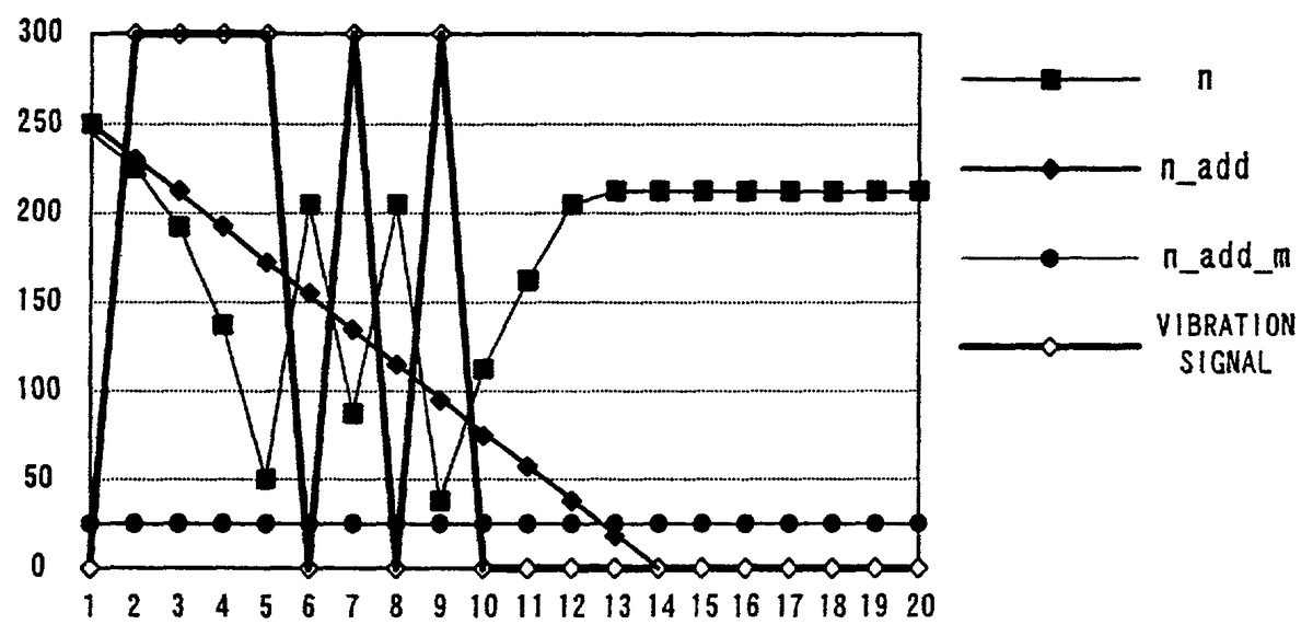
For example, if the player object comes into collision or contact with an enemy object or stationary object (FIG. 13,FIG. 14), “255” is set as an increment value n add of the count value n of the counter CT at the step S107, and “20” is set as a variation value n_add_m at the step S108. The count value n of the counter CT exceeds “255” over consecutive 4 frames excepting the first frame as shown in Table 1 andFIG. 15. Therefore, the vibration source507is continuously driven over the consecutive 4 frames, and thereafter the count value n exceeds “255” every two frames. The vibration source507generates a comparatively intense vibration driven every two frames.
TABLE 1INTENSE VIBRATION EXAMPLEVIBRATIONFRAMEnn_addn_add_mSIGNAL125525520022342352013193215201413219520155117520162061552007851352018200115200939952011011475200111695520012204352001321915200142190200152190200162190200172190200182190200192190200202190200
However, when starting an acceleration for the player object, comparatively weak vibration is generated. Accordingly, “150” is set as an increment value n_add at a step S111, and “10” is set as a variation value n_add_m at a step S112. Consequently, in this case the count value n exceeds “255” every two frames as shown in Table 2 (FIG. 16) so that the vibration source507is driven every two frames and the following 2 frames are suspended of vibration. At a next 1 frame the vibration source507is driven, and thereafter the vibration is suspended for 2 frames.
TABLE 2WEAK VIBRATION EXAMPLEVIBRATIONFRAMEnn_addn_add_mSIGNAL1150150100234140101316413010042812010151381101006238100100772901018152801009222701001026601011176501001211640100131463010014166201001517610100161760100171760100181760100191760100201760100
That is, where generating intense vibration, the vibration source507is continuously driven over several frames and then the vibration is gradually decreased as if driven every 2 frames. When weak vibration is to be generated, the driving source507is driven every 2 frames and then the vibration is gradually decreased in a manner driven every 3 frames. However, it is needless to say that the increment value n_add or the variation value n_add_m, that is, the vibration generating pattern as above, can be set in an arbitrary manner.
Incidentally, under a third vibration generating condition, i.e. where the player object (“jet ski”) is in contact with a water surface, the increment value n_add is set as a function of acceleration of the player object, generating intense or weak vibration depending upon the acceleration.
Incidentally, in the above embodiment the count value n of the counter CT is varied according to an increment value n_add or an variation value n_add_m, by executing the flowchart ofFIG. 12, in order to generate intense or weak vibration as shown inFIG. 15orFIG. 16. When the count value n exceeds “255”, the vibration flag F4is set to “1” to drive the vibration source507. That is, in the above embodiment whether to generate vibration by the vibration source507is determined by calculation in a real time manner.
Contrary to this, intense and weak vibration pattern data, read out of the program area22aof the external ROM21, may be respectively memorized on the flag/register area142of the RAM14, as shown, for example, inFIG. 17. By selectively reading out these vibration pattern data, the vibration source507may be controlled based on these pattern data. It can be considered that the intense vibration pattern data uses a vibration signal “0111101010000000” in a frame sequence of frames1–16in the afore-said Table 1. Meanwhile, the weak vibration pattern data may use a vibration signal “0101001001000000” in a frame sequence of frames1–16in the afore-mentioned Table 2. Incidentally, medium vibration pattern data may be memorized as required.
For example, when the player object is detected of its collision or contact at the step S101inFIG. 10, if intense vibration pattern data is read out, the vibration source507is not driven by a first frame. However, the vibration source507is continuously driven over the following 4 frames, and then at every 2 frames, thereafter being ceased of drive. For example, when an acceleration start is detected at the step S102inFIG. 10or a contact with a water surface is detected at the step S103, weak vibration pattern data is read out. Consequently, the vibration source507is driven at every 2 frames during the first 4 frames, and then driven at every 3 frames, thereafter being ceased of drive.
In the above embodiment, when the player object is hit by another object or the like, vibration is generated by the vibration source507of the vibration cartridge50loaded on the controller40. Vibration may be visually given to game images in timing related to this vibration. In such a case, the game-image vibration on the display30can be perceived with higher rapidity than the mechanical vibration caused by the vibration cartridge50of the controller40. Accordingly, mechanical vibration may be generated by the vibration cartridge50at the step S10inFIG. 9, and thereafter vibration is visually given to game images with a delay of 1 or 2 frames or more at the step S4or S7inFIG. 9.
For example, when it is detected at the step S101ofFIG. 10that the player object comes into contact or collision against another object, since intense vibration is generated on a game images, the display30is vibrated at the entire screen. In this case, the visual coordinate for a camera stated before may be varied bit by bit during the camera process of the step S4inFIG. 9.
When a condition of generating weak vibration is detected at the step S102or S103inFIG. 10, weak vibration is generated on the game image. The player object image only is given vibration that is displayed on the display30. In such a case, a plurality of polygon sets, constituting the player object, may be varied in a center coordinate position bit by bit in the rendering process at the step S7inFIG. 9.
Incidentally, whether to give vibration to a game image may be determined by a condition whether “F4=1” is detected at the step S128inFIG. 12. That is, when the vibration flag F4is at “1”, vibration is given to the game image, while when the flag is at “0”, no vibration is generated in the game image.
Although the present invention has been described and illustrated in detail, it is clearly understood that the same is by way of illustration and example only and is not to be taken by way of limitation, the spirit and scope of the present invention being limited only by the terms of the appended claims.
Claims
- A computer readable medium for use with a video game system comprising a video game machine, a hand-held controller connected to said video game machine and operable by a player to generate video game inputs, and a vibration source arranged to vibrate a housing of said hand-held controller, said computer readable medium having stored thereon instructions adapted to be executed by said video game machine, the instructions which, when executed, define a series at steps comprising: (a) detecting vibration generating conditions;(b) loading a counter with a count determined in accordance with the detected vibration generating conditions;(c) generating vibration control data for controlling said vibration source based on the count of said counter;and (d) performing the following steps one or more times: (d1) changing the count of said counter in accordance with a counter change value;and (d2) generating vibration control data for controlling said vibration source based on the changed count of said counter, wherein the counter change value is initially determined in accordance with the detected vibration generating conditions and changes at least once from the initially determined value.
- The computer readable medium according to claim 1 , wherein collisions between game objects are detected as vibration generating conditions.
- The computer readable medium according to claim 1 , wherein collisions between game objects in three-dimensional space are detected as vibration generating conditions.
- The computer readable medium according to claim 1 , wherein accelerations of game objects are detected as vibration generating conditions.
- The computer readable medium according to claim 1 , wherein vibration control data for controlling said vibration source is generated when the count of said counter exceeds a predetermined count value.
- The computer readable medium according to claim 1 , wherein the counter change value is an increment value for incrementing the count of said counter.
- The computer readable medium according to claim 1 , wherein the counter change value changes in accordance with a variation value which is also determined in accordance with the detected vibration generating conditions.
- The computer readable medium according to claim 1 , comprising an optical disc.
- The computer readable medium according to claim 1 , comprising a magnetic disc.
- The computer readable medium according to claim 1 , comprising a ROM cartridge.
- A storage medium for use with a video game system comprising a video game machine, a hand-held controller connected to said video game machine and operable by a player to generate video game inputs, and a vibration source arranged to vibrate a housing of said hand-held controller, said storage medium having stored thereon instructions adapted to be executed by said video game machine, the instructions which, when executed, define steps comprising: (a) detecting vibration generating condition;(b) loading a counter with a count determined in accordance with the detected vibration generating conditions;and (c) generating vibration control data for controlling said vibration source based on the count of said counter;and (d) performing the following steps one or more times: (d1) changing the count of said counter in accordance with a counter change value;and (d2) generating vibration control data for controlling said vibration source based on the changed count of said counter, wherein the counter chance value changes at least once from an initial value thereof.
- A storage medium for use with a video game system comprising a video game machine, a hand-held controller connected to said video game machine and operable by a player to generate video game inputs, and a vibration source arranged to vibrate a housing of said hand-held controller, said storage medium having stored thereon instructions adapted to be executed by said video game machine, the instructions which, when executed, define steps comprising: (a) detecting vibration generating conditions;(b) loading a counter with a count determined in accordance with the detected vibration generating conditions;(c) generating vibration control data for controlling said vibration source during a first video game frame based on the count of said counter;and (d) performing the following steps for at least one subsequent video game frame: (d1) changing the count of said counter in accordance with a counter change value;and (d2) generating vibration control data for controlling said vibration source based on the changed count of said counter, wherein the counter change value is initially determined in accordance with the detected vibration generating conditions and changes at least once from the initially determined value.
- A storage medium for use with a video game system comprising a video game machine, a hand-held controller connected to the video game machine and operable by a player to generate video game inputs, and a vibration source arranged to vibrate a housing of the hand-held controller, the storage medium having stored thereon instructions adapted to be executed by the video game machine, the instructions which, when executed, define steps comprising: (a) detecting a vibration generating condition;(b) loading a counter with an initial value in accordance with the detected vibration generating condition;and (c) generating control signals for controlling the vibration source during a first video game frame based on the count of said counter;and (d) performing the following steps for at least one subsequent video game frame: (d1) changing the count of the counter in accordance with a counter change value;and (d2) generating control signals for controlling the vibration source based on the changed count of the counter, wherein the counter change value changes at least once from an initial value thereof.
- The storage medium according to claim 13 , wherein the control signals comprise control signals for switching the vibration source on and off.
- The storage medium according to claim 13 , wherein the control signals are switch control signals that are supplied to a switch connected between the vibration source and a power supply.
- The storage medium according to claim 13 , wherein the control signals comprise first control signals for switching the vibration source ON and second control signals for switching the vibration source OFF.
- The storage medium according to claim 13 , wherein the generating comprises: comparing the counter values to a predetermined counter value;generating first control signals for switching the vibration source ON when given counter values have a first relationship with the predetermined counter value;and generating second control signals for switching the vibration source OFF when given counter values have a second relationship with the predetermined counter value.
- The storage medium according to claim 13 , wherein a relatively large counter change value provides intense vibration and a relatively small counter change value provides weak vibration.
- The storage medium according to claim 13 , wherein the counter change value changes in accordance with the type of vibration generating condition detected.
- The storage medium according to claim 13 , wherein the counter values change every video frame in accordance with the counter change value.
- The storage medium according to claim 13 , further comprising: setting a flag if a vibration generating condition is detected.
- The storage medium according to claim 13 , wherein a collision between game objects is detected as a vibration generating condition.
- The storage medium according to claim 13 , wherein a collision between game objects in three-dimensional space is detected as a vibration generating condition.
- The storage medium according to claim 13 , wherein an acceleration of a game object is detected as a vibration generating condition.
- A computer readable medium for use with a video game system comprising a video game processing system, controls operable by a player to generate video game inputs, and a vibration source, the computer readable medium having stored thereon instructions adapted to be executed by the video game machine, the instructions which, when executed, define a series of steps comprising: (a) detecting a vibration generating condition;(b) loading a counter with a count based on a counter change value that is determined in accordance with the detected vibration generating condition;(c) changing the counter change value;(c) generating vibration control data for controlling the vibration source based on the count of the counter;(d) performing the following steps one or more times: (d1) changing the count of the counter in accordance with the counter change value;(d2) changing the counter change value;and (d3) generating vibration control data for controlling the vibration source based on the count of the counter.
- The storage medium according to claim 24 , wherein the vibration control data comprises control signals for switching the vibration source on and off.
- The storage medium according to claim 24 , wherein the vibration control data comprises switch control signals that an supplied to a switch connected between the vibration source and a power supply.
- The storage medium according to claim 25 , wherein the vibration control data comprises first control signals for switching the vibration source ON and second control signals for switching the vibration source OFF.
- The storage medium according to claim 25 , wherein the generating of vibration control data comprises: comparing the count of the counter to a specified count value;generating first control signals for switching the vibration source ON when given counts of the counter have a first relationship with the specified counter value;and generating second control signals for switching the vibration source OFF when given counts of the counter have a second relationship with the specified counter value.
- The storage medium according to claim 25 , wherein a relatively large counter change value provides intense vibration and a relatively small counter change value provides weak vibration.
- The storage medium according to claim 25 , wherein the count of the counter changes every video frame.
- The storage medium according to claim 25 , further comprising: setting a flag if a vibration generating condition is detected.
- The storage medium according to claim 25 , wherein a collision between game objects is detected as a vibration generating condition.
- The storage medium according to claim 25 , wherein a collision between game objects in three-dimensional space is detected as a vibration generating conditions.
- The storage medium according to claim 25 , wherein an acceleration of a game object is detected as a vibration generating condition.
Disclaimer: Data collected from the USPTO and may be malformed, incomplete, and/or otherwise inaccurate.