U.S. Pat. No. 7,042,438
HAND MANIPULATED DATA APPARATUS FOR COMPUTERS AND VIDEO GAMES
Issue DateSeptember 6, 2003
Illustrative Figure
Abstract
A computer or video game device for generating hand manipulated data. The device consists of one or more sensors that are mounted on the human hand. The sensors are conveniently located for easy access and manipulation by opposing fingers on the same hand that the sensors are mounted on. This arrangement overcomes the limitations of a tabletop computer mouse by not requiring a planar surface, and by not requiring the user to hold onto the device. Additionally the sensors are located in such a way that they do not impede standard office procedures such as using a computer keyboard, writing with a pen, holding a phone, etcetera. The device can also be quickly and easily attached or removed by the user. Various embodiments of the invention include “wired”, “wireless”, multiple finger, universal right or left-hand, universal finger or thumb application, and universal side or top mounted sensors. Existing technologies and manufacturing techniques are utilized to minimize cost. Uses include personal computer, video game, and industrial applications.
Description
DESCRIPTION—FIGS.1A THROUGH FIG.12 FIGS. 1AthroughFIG. 12depict specific preferred embodiments of the present invention for purposes of illustration only. One skilled in the art will recognize from the following discussion that alternative embodiments of the structures and methods illustrated herein may be employed without departing from the invention. It is understood in these descriptions that conventional computer mice have a user programmable software capability. This allows the user to configure each computer mouse sensor to meet their personal requirements. As an example, a user can configure a mouse for left or right hand operation, define special buttons and scroll wheels, etcetera. The following descriptions preserve this user configuration capability. Additionally, these descriptions may use the word thumb or finger interchangeably. Now referring toFIGS. 1A and 1B; these figures represent a basic form of the invention by utilizing a single mouse stick10, and a single button12. (Note that a mouse-stick sensor is the type of mouse sensor commonly employed in the center of laptop computer keyboards. It looks like a small button and is gently pushed in various directions resulting in mouse cursor movement on the computer screen. The most recent production of mouse sticks also employ a built-in button that is activated by depressing the mouse stick. This button is most commonly configured by the user to be equivalent to the left mouse button on a conventional tabletop mouse. This dual-function mouse stick will be used for purposes of these discussions.) Sensors10and12are both mounted on the thumb side of a sensor bus14that is positioned on the middle digit of the index finger. The sensor bus14is ergonomically shaped so that movement of the finger joints is not inhibited. Sensor bus14would normally be lined inside with an expandable non-slip foam or similar product (not shown). This would allow sensor bus14to conform to a ...
DESCRIPTION—FIGS.1A THROUGH FIG.12
FIGS. 1AthroughFIG. 12depict specific preferred embodiments of the present invention for purposes of illustration only. One skilled in the art will recognize from the following discussion that alternative embodiments of the structures and methods illustrated herein may be employed without departing from the invention.
It is understood in these descriptions that conventional computer mice have a user programmable software capability. This allows the user to configure each computer mouse sensor to meet their personal requirements. As an example, a user can configure a mouse for left or right hand operation, define special buttons and scroll wheels, etcetera. The following descriptions preserve this user configuration capability. Additionally, these descriptions may use the word thumb or finger interchangeably.
Now referring toFIGS. 1A and 1B; these figures represent a basic form of the invention by utilizing a single mouse stick10, and a single button12. (Note that a mouse-stick sensor is the type of mouse sensor commonly employed in the center of laptop computer keyboards. It looks like a small button and is gently pushed in various directions resulting in mouse cursor movement on the computer screen. The most recent production of mouse sticks also employ a built-in button that is activated by depressing the mouse stick. This button is most commonly configured by the user to be equivalent to the left mouse button on a conventional tabletop mouse. This dual-function mouse stick will be used for purposes of these discussions.) Sensors10and12are both mounted on the thumb side of a sensor bus14that is positioned on the middle digit of the index finger. The sensor bus14is ergonomically shaped so that movement of the finger joints is not inhibited. Sensor bus14would normally be lined inside with an expandable non-slip foam or similar product (not shown). This would allow sensor bus14to conform to a wide range of finger sizes without twisting and slipping on the finger. As the user manipulates sensors10and12with the opposing thumb, the corresponding electrical signals are carried to a electronics interface box16by way of a flexible multi-conductor cable18. The interface box16then converts the sensory electrical signals to digital data. This mouse equivalent data is then provided to a computer20. This embodiment can be used to generate all basic types of mouse equivalent data. This includes but is not limited to the “double-click” function, and the “drag-and-drop” function. Of particular concern in this discussion is the ability to perform the computer “drag-and-drop” function. This is easily accomplished by the user manipulating the dual function mouse stick10in the same way as one would with a dual-function mouse stick on a laptop computer. In doing so, the operator uses the thumb against the mouse stick10to position the mouse cursor as desired. Then the built-in mouse stick button is depressed while the user highlights the desired item. The button is then released. Then the user places the mouse cursor over the highlighted item and re-depresses the mouse stick button. The user then moves the mouse cursor to the drop location. Then the mouse stick button is released to drop the item. Button12would typically be configured by the user to be equivalent to the right mouse button on a conventional tabletop mouse. Alternatively, button12may be configured as an on/off button. Although this embodiment describes the interface box16as a separate enclosure, it is understood that it can also be incorporated into the sensor bus14or the computer20. It is also understood that the electronics interface can have either a “wired” or “wireless” connection to the computer. Also notice that this unit is universal in that it can be worn on either the right or left hand. This is accomplished by removing the unit from the finger and rotating the unit 180 degrees with respect to an axis that is parallel to the index finger, or to an axis that is perpendicular to the index finger. When re-inserted onto the opposite hand, the mouse stick10will either be located toward the fingertip side of sensor bus14, or toward the wrist side. This location is determined by the axis chosen for rotation. The unit may also be worn on the index finger or the thumb. To switch to a thumb application, the user simply removes the unit from the index finger and repositions the unit onto the thumb with sensors10and12facing the opposing index finger. Additionally the sensors may be relocated to a dorsal or top position by simply rotating sensor bus14to re-position sensors10and12on the top or dorsal side of the finger or thumb. This universal right or left hand, universal index finger or thumb, and universal side or dorsal application is typical of many of the embodiments to follow.
Now referring toFIGS. 2A and 2B; these figures represent an embodiment of the invention that uses scroll-wheel sensors. This embodiment includes a button22, a dual function mouse stick24, a vertical navigation scroll-wheel26, and a horizontal navigation scroll-wheel28. These sensors are all mounted on the thumb side of a sensor bus30. Sensor bus30is positioned on the middle digit of the index finger and is ergonomically shaped so that movement of the finger joints is not inhibited. It is understood that while the dual function mouse stick is used to navigate throughout the computer operating system and within software applications, scroll-wheel sensors are typically only used to navigate within software applications. For example, the user may configure this embodiment to have scroll-wheel26configured for vertical navigation, and scroll-wheel28configured for horizontal navigation within a software application. This explanation of scroll-wheel usage is well known in the art. Sensor bus30would normally be lined inside with an expandable non-slip foam or similar product (not shown). This would allow the sensor bus30to conform to a wide range of finger sizes without twisting and slipping on the finger. As the user manipulates sensors22,24,26, and28with the opposing thumb, the corresponding electrical signals are carried to a electronics interface box32by way of a flexible multi-conductor cable34. The interface box32then converts the sensory electrical signals to digital data. This mouse equivalent data is then provided to a computer20. This embodiment can be used to generate all forms of mouse equivalent data. This includes but is not limited to the “double-click” function, the “drag-and-drop” function, and the “scroll-wheel” functions. Although this embodiment describes the interface box32as a separate enclosure, it is understood that it can also be incorporated into the sensor bus30or computer20. Also notice that the unit is universal in that it can be worn on either hand.
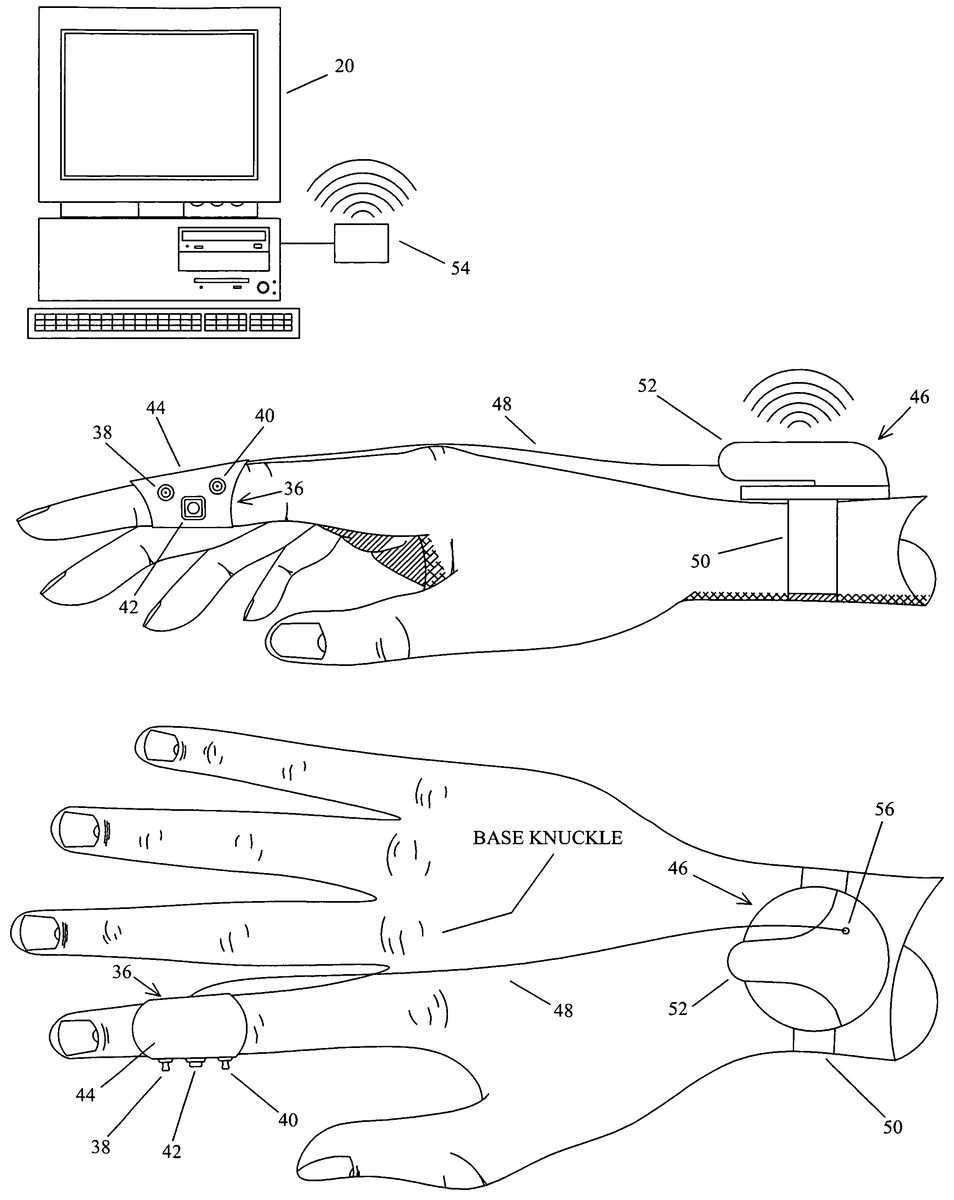
Now referring toFIGS. 3A,3B,3C, and3D; these figures represent a wireless embodiment of the invention that has retractable sensors. A sensor assembly36consists of a first dual function mouse stick38, a second dual function mouse stick40, and a button42. Sensors38,40, and42are all mounted on the thumb side of a sensor bus44. Sensor bus44is positioned on the middle digit of the index finger and is ergonomically shaped so that movement of the finger joints is not inhibited. Sensor bus44would normally be lined inside with an expandable non-slip foam or similar product (not shown). This would allow sensor bus44to conform to a wide range of finger sizes without twisting and slipping on the finger. The user manipulates sensors38,40, and42with the opposing thumb. The corresponding electrical signals are carried to a wrist mounted transmitter assembly46by way of a retractable multi-conductor cable48. Transmitter assembly46is attached to the user with a wrist strap50. Notice that transmitter assembly46has a docking area52to position the sensor assembly36onto. Transmitter46transmits the sensor signals to a receiver54. Receiver54then converts the sensory information to mouse equivalent data. This mouse equivalent data is then provided to a computer20. Transmitters and receivers of this type are currently used in the art for wireless computer mice and keyboards. This embodiment gives the user the flexibility to configure either mouse stick for mouse cursor movement. The remaining mouse stick is then configured to generate “scroll-wheel” equivalent data. This “scroll-wheel” mouse stick is then used to navigate within software applications. Button42would typically be configured by the user as a click button, or as an on/off button. Notice that cable48exits the sensor assembly36in a manner that directs it between the index finger base knuckle, and the middle finger base knuckle. (The base knuckle is defined inFIG. 3B.) This neatly dresses the cable48between the two knuckles in a captive fashion that prevents the cable48from slipping off the top of the hand. This eliminates the need for an additional cable hold down strap between the sensor assembly36and the transmitter assembly46. Cable48is retracted and extracted from the transmitter assembly46through opening56. This spring loaded retraction keeps the cable48snug between the knuckles, and allows the sensor assembly36to be retracted and positioned onto docking area52of the transmitter assembly46as shown inFIGS. 3C and 3D. The design and manufacture of retractable cabling is well known in the electrical extension cord, robotic, and instrumentation industries. This embodiment can be used to generate all forms of mouse equivalent data. This includes but is not limited to the “double-click” function, the “drag-and-drop” function, and the “scroll-wheel” functions. Although this embodiment describes the transmitter assembly46as a separate enclosure, it is understood that it can also be incorporated into the sensor assembly36. Likewise, receiver54could be incorporated within computer20.
Now referring toFIGS. 4A,4B,4C, and4D; these figures represent a second wireless embodiment of the invention that has retractable sensors. In this embodiment a sensor assembly58is mounted on the last digit of the index finger. Sensor assembly58consists of a sensor bus60, a first dual function mouse stick62mounted on the dorsal tip of sensor bus60, a second dual function mouse stick64mounted on the thumb side of sensor bus60, and a first button66and second button68both of which are mounted on the thumb side of sensor bus60. Notice that sensor bus60is ergonomically shaped so that the finger pad is not covered, and so that movement of the finger joint is not inhibited. The finger pad is defined inFIG. 4Aas that portion of the finger or thumb that is normally used to obtain fingerprints. Having the finger and thumb pads exposed will retain the touch senses of the user's fingertip as needed for keyboard operation and other functions. Sensor bus60would normally be lined inside with an expandable non-slip foam or similar product (not shown). This would allow sensor bus60to conform to a wide range of finger sizes without twisting and slipping on the finger. The user manipulates sensors62,64,66, and68with the opposing thumb. Alternatively, sensor62may also be manipulated by moving the index fingertip against an alternate surface such as a tabletop, the user's pant-leg, the armrest of a chair, etcetera. Also notice that sensor62is positioned just far enough from the finger tip so as not to interfere with keyboard operation, but yet is positioned forward enough to allow manipulation with the thumb or alternate surface. Sensory electrical signals are carried to a wrist mounted transmitter assembly70by way of a retractable multi-conductor cable72. Transmitter assembly70is attached to the user with a wrist strap74. Notice that transmitter assembly70has a first recess area76to position the sensor assembly58into. Additionally, first recess area76has a second recess area78for the side-mounted sensors64,66, and68to fit into. Transmitter70transmits the sensor signals to a receiver80. Receiver80then converts the sensory information to mouse equivalent data. This mouse equivalent data is then provided to a computer20. Transmitters and receivers of this type are currently used in the art for wireless computer mice and keyboards. This embodiment gives the user the flexibility to configure either mouse stick for mouse cursor movement. The remaining mouse stick is then configured to generate “scroll-wheel” equivalent data. This “scroll-wheel” mouse stick is then used to navigate within software applications. Buttons66and68would typically be configured by the user either as a click button, or as an on/off button. Notice that cable72exits the sensor assembly58in a manner that directs it between the index finger base knuckle, and the middle finger base knuckle. This neatly dresses the cable72between the two knuckles in a captive fashion that prevents the cable72from slipping off the top of the hand. This eliminates the need for an additional cable hold down strap between the sensor assembly58and the transmitter assembly70. Cable72is retracted and extracted from the transmitter assembly70through opening82. This spring loaded retraction keeps the cable72snug between the knuckles, and allows the sensor assembly58to be retracted and docked into recess areas76and78of the transmitter assembly70as shown inFIGS. 4C and 4D. The design and manufacture of retractable cabling is well known in the electrical extension cord, robotic, and instrumentation industries. This embodiment can be used to generate all forms of mouse equivalent data. This includes but is not limited to the “double-click” function, the “drag-and-drop” function, and the “scroll-wheel” functions. Although this embodiment describes the transmitter assembly70as a separate enclosure, it is understood that it can also be incorporated into the sensor assembly58. Likewise, receiver80could be incorporated within computer20. Although not shown, an additional feature that could be incorporated into this embodiment would be a second fingertip sensor that is mounted on the wrist side of sensor bus60. This would be directly opposite and symmetric to sensor62and would be used as a fingertip sensor when the unit is placed on the thumb or the opposite hand. This would permit universal right or left-hand, or universal finger or thumb operation. Yet another embodiment (not shown) could include a rotatable split ring sensor bus. This would employ two adjacent rings where sensors64,66, and68would be on a first ring, and sensor62would be on a second ring. This second ring would have a portion removed to expose the finger pad. This embodiment would allow sensor62to be repositioned (rotated to the top) when relocating the assembly from the index finger to a thumb, or to a different hand.
Now referring toFIGS. 5A, and5B; these figures represent a wireless embodiment of the invention that is well suited for overhead computer presentations. In this embodiment a sensor assembly71is mounted on the first digit of the index finger. Sensor assembly71consists of a sensor bus73. Mounted on the thumb side of sensor bus73are a dual function mouse stick75, a first mouse button77, a second mouse button79, and a laser pointer activation button81. Mounted on the top or dorsal side of sensor bus73is a laser pointer83. Notice that sensor bus73is ergonomically shaped so that movements of the finger joints are not inhibited. Sensor bus73would normally be lined inside with expandable non-slip foam or similar product (not shown), or a hook and loop fastening strap (also not shown). This would allow sensor bus73to conform to a wide range of finger sizes without twisting and slipping on the finger. The user manipulates sensors75,77,79, and81with the opposing thumb. This is accomplished by using the thumb tip, or the side of the thumb as may be appropriate. Note that laser pointer83only generates a laser output85when the laser pointer button81is activated. Sensory output is presented to the electronics interface (wireless transmitter & battery that are not shown) that are internal to sensor assembly71. Notice the larger sensor bus73for enclosing the electronics interface (wireless transmitter and or receiver), and the battery. The electronics interface then transmits the sensor signals to a receiver87. Receiver87then converts the sensory information to mouse equivalent data. This mouse equivalent data is then provided to a computer20. (Computer input devices that include laser pointers are currently used in the art for overhead computer presentations. These are handheld devices that are shaped like a television remote control.) Buttons77,79, and81would typically be configured by the user either as a click button, an on/off button, a laser pointer button, a presentation “page forward” or “page reverse” button, or even a mode button that will switch the unit between different operational modes. This embodiment can be used to generate all forms of mouse equivalent data. This includes but is not limited to the “double-click” function, the “drag-and-drop” function, and etcetera. Although this embodiment describes the receiver assembly87as a separate enclosure, it is understood that it can also be incorporated within computer20. Naturally this embodiment can be made without laser pointer83.
Now referring toFIGS. 6A and 6B; these figures represent a universal right or left-hand, and universal thumb or index finger embodiment of the invention. A sensor assembly87utilizes a mini track-ball84, a first button86, a second button88, and a dual function mouse stick89. The use and manufacture of track-ball sensors is well known in the art. Sensors84,86, and88are all mounted on the index finger side of a thumb mounted sensor bus90. Sensor89is mounted on a rotatable bus extension91. Bus extension91is able to pivot toward the front or rear of bus90. This permits the user to conveniently re-position sensor89for either right or left-hand operation, and thumb or index finger operation. In doing so the user removes the unit from the thumb, then re-positions sensor bus90on the opposite thumb with sensors84,86, and88facing the index finger, then sensor89is rotated toward the tip of the thumb. Alternatively, the thumb mounted sensor bus could be re-positioned on the index finger of the same hand with sensors84,86, and88facing the thumb. Sensor89would then be rotated toward the fingertip. Once rotated into position, bus extension91is held in place by a recessed detent93. The underside of bus extension91has a male portion that securely snaps into detent93. Not shown is the second detent underneath the current position of bus extension91. Sensor bus90is mounted on the last digit of the thumb or finger and is ergonomically shaped so that movement of the finger joint is not inhibited. Additionally, notice that bus90does not cover the thumb pad. This preserves the tactile senses of the thumb for holding a writing pen, etcetera. Sensor bus90would normally be lined inside with an expandable non-slip foam or similar product (not shown). This would allow sensor bus90to conform to a wide range of finger or thumb sizes without twisting and slipping on the finger. As the user manipulates sensors84,86,88and89with an opposing finger(s) or thumb, the corresponding electrical signals are carried to a electronics interface box92by way of a flexible multi-conductor cable94. This cable is neatly dressed away from the hand with a wrist strap96. The interface box92converts the sensory electrical signals to digital data. This mouse equivalent data is then provided to a computer20. In this embodiment the user would configure the track-ball84and the mouse stick89for either mouse cursor movement, or to perform the scroll-wheel function. Buttons86and88would typically be configured by the user to be equivalent to the left and right buttons of a conventional tabletop computer mouse. Notice in this embodiment that sensors84,86,88, and89are positioned on sensor bus90so as not to impede thumb or finger interaction with the computer keyboard. Additionally, it is seen that the sensors will not be accidentally activated when using the computer keyboard. Although this embodiment describes the interface box92as a separate enclosure, it is understood that it can also be incorporated into the sensor bus90, or the computer20. Also notice that sensor89may also be manipulated by moving the thumb or finger tip against an alternate surface such as the side or top of a table, the user's pant-leg, the armrest of a chair, etceteras. Also notice that sensor89is positioned just far enough from the thumb tip so as not to interfere with keyboard operation, but yet is positioned forward enough to allow manipulation with a finger or alternate surface. Also notice that bus extension91could be implemented in different ways. For example, bus extension91could rotate on an axis perpendicular to that shown in this embodiment, etcetera. Yet another embodiment (not shown) would be a different kind of sensor bus that allowed the user to finely adjust the sensor position so as to obtain a customized fit. An example of this would be a bus extension that allows the user to adjust the position of the sensor back and forth relative to the fingertip.
Now referring toFIGS. 7A and 7B; these figures represent a multi-finger embodiment of the invention. Here a multi-finger assembly99includes a dual function mouse stick98mounted on the dorsal tip of a first sensor bus100that is positioned on the last digit of the index finger. A optical sensor102and a button104are mounted on the thumb side of sensor bus100. The manufacture and use of optical sensors is well understood in the computer mouse and instrumentation industries. The user would manipulate optical sensor102by rubbing the thumb over and across it. Physical contact, or near physical contact must be made with optical sensor102in order to manipulate it. This characteristic trait will help prevent accidental sensor activation while typing, etcetera. Although not shown, it may be necessary to place an optical filter over the optical window of sensor102in order to obtain the proper optical characteristics from the skin of the user's thumb. Also, the optical electronics associated with sensor102may be housed locally in sensor bus100, or remotely located by fiber optic cable to the transmitter130. A second sensor bus106is mounted on the middle digit of the index finger and is attached to the first sensor bus100by way of a flexible joint108and a multi-conductor cable harness110. Sensor bus106contains a touch pad sensor112, and a button114both of which are mounted on the thumb side of sensor bus106. A touch pad sensor is the type of sensor commonly located adjacent to the keyboard on laptop computers. These sensors tend to be somewhat flexible and malleable in nature. Here the touch pad sensor112is slightly molded to match the contour of sensor bus106. The touch pad sensor112is manipulated by the user rubbing the opposing thumb on the sensor in the direction of desired cursor movement. A third sensor bus116is mounted on the last digit of the middle finger. Here a mini track-ball sensor118is mounted on the dorsal or top side of sensor bus116. Mounted on the thumb side of sensor bus116is a first button120, and a second button122. A forth sensor bus124is mounted on the last digit of the ring finger. On the thumb side of sensor bus124is mounted a first button126, and a second button128. A fifth sensor bus101is mounted on the last digit of the thumb. Mounted on the dorsal or top side of sensor bus101is a button103and a dual function mouse stick105. Sensors103and105can be easily manipulated by one or more of the opposing fingers. Additionally, sensor bus101can be rotated to position sensors103and105toward the index finger in a side-mounted fashion. Notice that the multi-conductor cable harness110connects all five sensor bus assemblies to the transmitter130. Transmitter130transmits the sensor information to receiver132. Receiver132then converts the sensory information to mouse equivalent data and presents it to a computer20. Transmitter130is attached to the user with a wrist strap134. Whether the application is computer, video game, industrial, or other; the user will configure each sensor as desired for the application at hand. All of the finger sensors described in this embodiment are easily accessible by the opposing thumb. Likewise, the thumb-mounted sensors are easily accessible by one or more of the fingers. Additionally, dorsal mounted sensors98,103,105and118can be activated by manipulating against an alternate surface such as a tabletop, the user's leg, the armrest of a chair, etcetera. Notice that sensors98,103,105and118are positioned far enough back from the fingertip so as not to interfere with computer keyboard operation, but yet are far forward enough to be easily manipulated by the thumb, finger(s), or an alternate surface. Also notice in this embodiment that each sensor bus is ergonomically shaped to not block the fingertip touch senses, or impede joint movement. This ergonomic design will not impede computer keyboard operation, or other similar duties performed by the hand.
Now referring toFIGS. 8A,8B and8C; these figures demonstrate how the invention can be utilized by the user without interfering with other standard procedures. These figures will incorporate sensor assemblies from previously discussed embodiments. Here inFIG. 8Awe see the sensor assembly36fromFIG. 3A, sensor assembly58fromFIG. 4A, and sensor assembly87fromFIG. 6Abeing used with an ordinary drinking glass148. Notice that the user retains finger flexibility as needed to hold glass148without accidentally activating any sensors. Now referring toFIG. 8Bwe see the sensor assembly36fromFIG. 3A, sensor assembly58fromFIG. 4A, and sensor assembly87fromFIG. 6Abeing used with an ordinary writing pen144. Notice that the user can hold and write with the pen without accidentally activating any sensors, and without impairment of finger joint movement. InFIG. 8Cwe see the multi-finger embodiment99, computer20, and wireless receiver132fromFIG. 7Abeing used with a computer keyboard138. Notice that the thumb and finger tips are not covered and that finger joint movement is not impaired. This embodiment preserves the fingertip touch senses and joint movement of the user as needed for computer keyboard operation. Also notice that the sensors are located in a manner that prevents accidental sensor activation while typing. It is understood that there may be some tasks that will make it difficult to not accidentally activate a sensor. Under these circumstances the user can simply temporarily turn the unit off. This could be very easily performed by configuring one of the sensor buttons as an on/off button and using it accordingly. Alternatively the user could even momentarily remove the device, or just retract the sensor assemblies as described previously forFIGS. 3D and 4D.
Now referring toFIG. 9. This embodiment demonstrates the invention being used as a dual-hand video game controller. Here a game pad150, a first button152, and a second button154are mounted on the thumb side of a sensor bus156. A game pad is the type of sensor commonly deployed on video game controllers. It functions in the same manner as a joystick controller but has a much lower profile. Sensor bus156is mounted on the middle digit of the index finger of the right hand. Located on the first digit of this index finger is a transmitter158. Transmitter158is connected to the sensor bus156with a multi-conductor cable160. Transmitter158transmits the sensory information to a receiver162. Receiver162then conditions the sensory information to a data-type that is acceptable to a video game box164. The video game box164then presents the corresponding audio and video signals to a television166. Located on the left hand of the user is a second sensor assembly168, and a second transmitter assembly170. Notice that these assemblies168and170are of a universal design in that they can be used on either the right or left hand. Also notice the contoured pivot surfaces between each assembly that allows the user to move each finger joint as normal. The user manipulates the sensors with the opposing thumb of each hand in order to play video games. Notice that the user is not required to hold onto a controller as would be the case with the current art. Instead the user's hands are free to use an additional controller, a computer keyboard, etcetera. Note that the user may choose to use one or two controllers depending on the user's skill level and the type of video game being played. As with the previous discussion, these assemblies may be mounted on the thumb(s), other fingers of the hand, or both.
Now referring toFIG. 10. Here we have a representative schematic of a typical embodiment of the invention. A variable number and type of sensors are manipulated by the user and are represented here as sensor input(s)172labeled “1” through “N”. The electrical signals generated by sensor(s)172are converted to computer mouse equivalent data by a sensor to computer electronics interface174. Electronics174then provide the mouse equivalent data to a computer176. This technology is not new to the art as this is the design approach for most all non-wireless computer mice in the industry today. Note that the interface electronics174may be packaged with computer176rather than being a separate unit.
Now referring toFIG. 11. Here we have a representative schematic of a typical wireless embodiment of the invention. A variable number and type of sensors are manipulated by the user and are represented here as sensor input(s)172labeled “1” through “N”. The electrical signals generated by sensor(s)172are conditioned by a sensor to transmitter electronics interface178. Interface178presents the sensor information to a transmitter180. Transmitter180and electronics interface178are both powered by a battery182. Transmitter180transmits the sensory information to a receiver184. The received sensor information is then conditioned by a receiver to computer electronics interface186. Electronics interface186then presents the mouse equivalent data to a computer176. This technology is not new to the art as this is the design approach for most all wireless computer mice and keyboards in the industry today. Additionally, note that the receiver184and interface electronics186could be incorporated into the computer176rather than being a separate unit(s). Likewise, electronics178, transmitter180, and battery182could all be designed into a single package with or without the sensors.
Now referring toFIG. 12. Here we have a representative schematic of a typical dual hand wireless video game embodiment of the invention. A variable number and type of sensors are manipulated by the user and are represented here as a sensor input(s)188labeled “1” through “L” for the left hand, and a input(s)190labeled “1” through “R” for the right hand. The electrical signals generated by left hand sensor(s)188and right hand sensor(s)190are respectively conditioned by a left hand sensor to transmitter electronics interface192, and a right hand sensor to transmitter electronics interface194. Left-hand interface192presents the sensor information to the left-hand transmitter196. Likewise the right hand interface194presents the sensor information to the right hand transmitter198. The left hand transmitter196and electronics interface192are both powered by a battery200. Accordingly the right hand transmitter198and electronics interface194are both powered by a battery202. Transmitters196and198transmit their respective sensory information to a receiver204. The received sensor information is then conditioned by a receiver to video game electronics interface206. Electronics interface206then presents the video game equivalent data to a video game electronics box208. The electronics box208then presents the video game audio and video signals to a television210. This technology is not new to the art as wireless computer mice and keyboards are manufactured to work simultaneously with a single receiver assembly. This same technology approach is used here for the dual hand video game controller. Additionally, note that the receiver204and interface electronics206could be incorporated into the video game electronics box208rather than being a separate unit(s).
SUMMARY, RAMIFICATIONS, AND SCOPE
Accordingly, the reader will see that this device consists of one or more sensors that are mounted on the human hand. The sensors are conveniently located for easy access and manipulation by an opposing finger or thumb from the same hand that the sensors are mounted on. This arrangement overcomes the limitations of a tabletop computer mouse by not requiring a planar surface, and by not requiring the user to hold onto the device. Additionally the sensors are located in such a way that they do not impede standard office procedures such as using a computer keyboard, writing with a pen, holding a phone, etceteras. The device can also be quickly and easily attached or removed by the user. Various embodiments of the invention include “wired”, “wireless”, multiple finger, universal thumb or finger application, universal side or dorsal mounted sensors, and universal right or left-hand operation. Existing technologies and manufacturing techniques are utilized to minimize cost. Uses include personal computer, video game, and industrial applications. Furthermore, the device has the additional advantages in that:The device can use new sensor types as they are developed.The device is ergonomically shaped so that movement of the finger joints is not inhibited.The device can be used by handicapped persons.The device does not require the user to remove the hand from the keyboard area in order to generate mouse equivalent data.The device prevents accidental sensor activation when using the computer keyboard.The device prevents accidental sensor activation when performing other standard office duties such as writing with a pen, holding a phone, etceteras.The device does not block the tactile senses of the finger-pads whereby computer keyboard use is not impaired.The device does not require the user to learn a new set of hand-eye coordination skills.The device does not require wrist movement that would agitate persons suffering from carpal-tunnel-syndrome.
Although the descriptions above contains many specificities, these should not be construed as limiting the scope of the invention but as merely providing illustrations of some of the presently preferred embodiments of this invention. For example, this invention could be embodied as a remote control for radio controlled airplanes, cars, or even a television. The invention can also be used in an industrial or research setting for controlling robots, cranes, machines, or other equipment. Additionally the sensors to be used can be of any type, shape, or design. Additional variations include but are not limited to the following:The device could have the interface electronics and or wireless transmitter mounted inside the same enclosure that the sensors are mounted on, or on an adjacent finger-mounted enclosure.The device could utilize a different approach to attaching the sensors to the hand such as using adjustable straps or hook-and-loop fasteners, using other elastic materials, etcetera.The device could have a sensor bus with a matrix of sensor receptacles whereby the user places the desired sensor types at the locations of choice.The device could be designed to work with multiple machines and/or computers. For example, a multi-finger assembly as previously shown inFIG. 7Acould have each finger assembly control a different machine.
While preferred embodiments of the present invention has been disclosed and described in detail, and various alternate embodiments have been described, it will be understood by those skilled in the art that various changes in form and detail may be made to the present invention without departing from the spirit and scope of the invention. Thus the scope of the invention should be determined by the appended claims and their legal equivalents, rather than by the examples given.
Claims
- A hand manipulated data apparatus for entering commands to a machine, comprising: a. a sensor(s) for accepting hand manipulations, said sensor(s) having a signal output, b. a electronics interface for converting the signal output from said sensor(s) to a format acceptable to said machine, c. attaching means for affixing said sensor(s) to the human hand(s) in combination with said electronics interface, d. said attaching means further positioning said sensor(s) to be manipulated by the opposing finger(s) and/or thumb of the same hand that said sensor(s) are mounted on, whereby said sensor(s) are only activated by a deliberate effort of the user, e. said attaching means further positioning said sensor(s) so as to avoid accidental sensor activation, whereby a user can hold a glass and perform other standard hand operations without accidentally activating a sensor(s).
- The hand manipulated data apparatus of claim 1 wherein said attaching means is further ergonomically shaped to expose the finger and/or thumb pads so as to preserve the tactile and griping qualities of the human hand.
- The hand manipulated data apparatus of claim 1 wherein said attachment means is further ergonomically shaped, and said sensor(s) are further placed on said attachment means to facilitate universal right or left hand operation and/or universal finger or thumb operation, whereby the user can easily remove the device from one finger, thumb, or hand, and relocate the device on a different finger, thumb, or hand.
- The hand manipulated data apparatus of claim 1 wherein said attachment means further positions a part or all of said sensor(s) in a relocatable fashion whereby a part or all of said sensor(s) can be repositioned on said attachment means for universal right or left-hand operation, and/or universal thumb or finger operation.
- The hand manipulated data apparatus of claim 1 wherein said attachment means further positions a part or all of said sensor(s) on said attachment means in an adjustable fashion whereby the user can adjust and/or change the location(s) of a part or all of said sensor(s) to obtain customized sensor placement.
- The hand manipulated data apparatus of claim 1 wherein said attachment means further includes a non-slip interior surface for securing said attachment means onto the hand whereby said attachment means will not twist and turn while said sensor(s) are being manipulated.
- The hand manipulated data apparatus of claim 1 wherein said attachment means further includes a adjustable conforming means for securing said attachment means to a wide range of finger shapes and sizes, whereby a single apparatus is capable of fitting a wide range of users.
- The hand manipulated data apparatus of claim 1 wherein said electronics interface is in a separate enclosure from said attachment means, and further includes a transferring means for conveying said sensor output to said electronics interface, whereby said attachment means for mounting said sensor(s) can be smaller in size.
- The hand manipulated data apparatus of claim 8 wherein said transferring means comprises a cable structure that is routed between the base knuckles of the hand in a captive fashion, whereby the cable will not slip off the top of the hand, and the need for additional cable hold down straps is minimized or eliminated.
- The hand manipulated data apparatus of claim 8 wherein said transferring means is a cable structure that exits said attachment means in a manner that facilitates universal right or left hand operation, and/or universal thumb or finger operation.
- The hand manipulated data apparatus of claim 8 wherein said transferring means is a cable structure that is retractable to and extendable from said electronics interface enclosure, whereby said cable is maintained in a gently snug fashion.
- The hand manipulated data apparatus of claim 8 wherein said electronics interface enclosure further includes a relocating means for repositioning said attachment means, whereby said attachment means can be removed and docked onto or into said relocating means.
- The hand manipulated data apparatus of claim 12 further including a cable retraction and extension means, wherein said transferring means is a cable structure that is retractable to and extendable from said relocating means, whereby said cable is maintained in a gently snug fashion when said sensor(s) is deployed, and the cable is neatly withdrawn when said attachment means is retracted.
- A method for detecting hand manipulations and entering the corresponding commands to a machine, comprising the steps of: a. acquiring hand manipulation information from one or more sensor(s), b. attaching said sensor(s) to the human hand(s) so that said sensor(s) can be manipulated by the opposing finger(s) and/or thumb of the same hand that said sensor(s) are mounted on, whereby said sensor(s) are only activated by a deliberate effort of the user, c. further attaching said sensor(s) so as to avoid accidental sensor activation, whereby a user can hold a glass and perform other standard hand related duties without accidentally activating a sensor(s), d. outputting signals from said sensor(s) that correspond to said hand manipulations, e. converting the output from said sensor(s) to a to a format that is acceptable to said machine, f. delivering said formatted signals to said machine.
- The method of claim 14 wherein said step of attaching purposely exposes the finger and/or thumb pads so as to preserve the tactile and griping qualities of the human hand.
- The method of claim 14 wherein said step of attaching further places said sensor(s) on the human hand(s) to facilitate universal right or left hand operation and/or universal finger or thumb operation, whereby the user can easily remove the device from one finger, thumb, or hand, and relocate the device on a different finger, thumb, or hand.
- The method of claim 14 wherein said step of attaching further positions a part or all of said sensor(s) in a relocatable fashion whereby a part or all of said sensor(s) can be repositioned on the human hand(s) for universal right or left-hand operation, and/or universal thumb or finger operation.
- The method of claim 14 wherein said step of attaching further positions a part or all of said sensor(s) on the human hand(s) in an adjustable fashion whereby the user can adjust and/or change the location(s) of a part or all of said sensor(s) to obtain customized sensor placement.
- The method of claim 14 wherein said step of attaching further provides a non-slip means for securing said sensor(s) onto the hand(s) whereby said sensor(s) will not twist and turn while said sensor(s) are being manipulated.
- The method of claim 14 wherein said step of attaching further includes a adjustable conforming means for securing said sensor(s) to a wide range of finger shapes and sizes.
- The method of claim 14 wherein said step of attaching further includes a relocating means for removing said sensor(s) from their operating position, and repositioning said sensor(s) for storage, whereby said sensor(s) can be removed and docked onto or into said relocating means.
- The method of claim 14 wherein said step of converting is physically removed from said sensor(s), this step further including a transferring of said sensor output to said step of converting, whereby said sensor attaching can be smaller in size.
- The method of claim 22 wherein said transferring comprises a cable structure that is routed between the base knuckles of the hand in a captive fashion, whereby the cable will not slip off the top of the hand, and additional steps of securing the cable are minimized or eliminated.
- The method of claim 22 wherein said step of transferring includes a cable structure that exits said sensor(s) in a manner that facilitates universal right or left hand operation, and/or universal thumb or finger operation.
- The method of claim 22 wherein said step of transferring includes a cable structure that is further maintained in gently snug fashion.
- The method of claim 22 wherein said step of transferring includes a cable structure that can be further repositioned for convenient use, and storage.
Disclaimer: Data collected from the USPTO and may be malformed, incomplete, and/or otherwise inaccurate.