U.S. Pat. No. 7,034,832
COMPUTER READABLE MEDIUM STORING 3-D IMAGE PROCESSING PROGRAM, 3-D IMAGE PROCESSING METHOD AND DEVICE, 3-D IMAGE PROCESSING PROGRAM, AND VIDEO GAME DEVICE
AssigneeKonami Corporation
Issue DateApril 1, 2002
Illustrative Figure
Abstract
In order to generate, on a display screen, a natural-looking deformed image obtained by intentionally distorting an original image, a buffer 21 comprises an original image storage section 210 which stores an original image, and a model storage section 211 which stores a 3-D model, comprising a plurality of polygons, and having a shape in which at least a portion of a plane is distorted in 3-D space. A drawing processor 10 comprises an image pasting section 100, which reads an original image from the original image storage section 210, reads a 3-D model from the model storage section 211, and pastes the above original image, as a texture, onto the above 3-D model, and a deformed image drawing section 101, which, by writing to a frame buffer 213, draws on a monitor 22 a deformed image, which is an image of the above 3-D model onto which an original image has been pasted, as seen from a prescribed camera viewpoint.
Description
DESCRIPTION OF THE PREFERRED EMBODIMENTS Note that throughout this specification the terms “3-dimensional” and “2-dimensional” are expressed as “3-D” and “2-D”, respectively, for short. FIG. 1is a block diagram showing one aspect of a video game device of this invention. This video game device comprises a game main unit GM and recording medium200on which is recorded program data. The game main unit GM comprises a CPU (central processing unit)1; a bus line2connected to the CPU1and having an address bus, data bus, and control bus; and a graphic data generation processor3. The bus line2is connected to an interface4; RAM (random access memory) or other main memory5; ROM (read-only memory)6; an expansion circuit7; a parallel port8; a serial port9; a drawing processor10; an audio processor11; a decoder12; and an interface circuit13. The drawing processor10is connected to a buffer21, and also to a television monitor (hereafter “monitor”)22; the audio processor11is connected to a buffer23, and to a speaker25via an amplifier circuit24. The decoder12is connected to a buffer26, and also to a recording medium driver27; the interface circuit13is connected to memory28, and also to a controller29. The form of this video game device changes according to the application. For example, when the video game device is configured for home use, the monitor22and speaker25are separate from the game main unit GM. On the other hand, when the video game device is configured for commercial use, all the component elements shown inFIG. 1are housed in a single housing. When this video game device is configured with a personal computer or workstation as the core, the monitor22corresponds to the computer display; the drawing processor10, audio processor11, and expansion circuit7correspond to a portion of the program data recorded on the recording medium200or to hardware on an expansion board mounted in an expansion slot of the computer; and the ...
DESCRIPTION OF THE PREFERRED EMBODIMENTS
Note that throughout this specification the terms “3-dimensional” and “2-dimensional” are expressed as “3-D” and “2-D”, respectively, for short.
FIG. 1is a block diagram showing one aspect of a video game device of this invention. This video game device comprises a game main unit GM and recording medium200on which is recorded program data. The game main unit GM comprises a CPU (central processing unit)1; a bus line2connected to the CPU1and having an address bus, data bus, and control bus; and a graphic data generation processor3.
The bus line2is connected to an interface4; RAM (random access memory) or other main memory5; ROM (read-only memory)6; an expansion circuit7; a parallel port8; a serial port9; a drawing processor10; an audio processor11; a decoder12; and an interface circuit13. The drawing processor10is connected to a buffer21, and also to a television monitor (hereafter “monitor”)22; the audio processor11is connected to a buffer23, and to a speaker25via an amplifier circuit24. The decoder12is connected to a buffer26, and also to a recording medium driver27; the interface circuit13is connected to memory28, and also to a controller29.
The form of this video game device changes according to the application. For example, when the video game device is configured for home use, the monitor22and speaker25are separate from the game main unit GM. On the other hand, when the video game device is configured for commercial use, all the component elements shown inFIG. 1are housed in a single housing. When this video game device is configured with a personal computer or workstation as the core, the monitor22corresponds to the computer display; the drawing processor10, audio processor11, and expansion circuit7correspond to a portion of the program data recorded on the recording medium200or to hardware on an expansion board mounted in an expansion slot of the computer; and the interface circuit4, parallel port8, serial port9, and interface circuit13correspond to hardware on an expansion board mounted on an expansion slot of the computer. The buffers21,23,26correspond to areas in main memory5or in expansion memory (not shown). In this aspect, an example is explained for the case in which the video game device is configured for home use.
Next, each of the component elements shown inFIG. 1is explained. The graphic data generation processor3plays a role similar to that of a coprocessor of the CPU1. That is, the graphic data generation processor3employs parallel processing to execute coordinate conversions, light source calculations, and, for example, matrix and vector operations in fixed-decimal point format. The main processing tasks performed by this graphic data generation processor3is to determine addresses in the display area of the image being processed based on coordinate data for each vertex in image data supplied by the CPU1in 2- or 3-D space, movement amount data, and rotation amount data, and to return this data to the CPU1, as well as to calculate image brightness according to distances from a virtually set light source.
The interface circuit4is an interface for use with a peripheral device, such as a mouse, trackball, or other pointing device. The ROM6stores program data as the operating system for the video game device. In terms of personal computers, this corresponds to the BIOS (basic input/output system).
The expansion circuit7performs processing to expand compressed images which have been compressed by intra-frame coding conforming to the MPEG (Moving Picture Engineering Group) standard for video and the JPEG (Joint Picture Engineering Group) standard for still images. Expansion processing is decoding processing (decoding of data encoded using a VLC, or variable-length code), inverse quantization processing, IDCT (inverse discrete cosine transform) processing, processing to restore intra-frame-coded images, and similar. The drawing processor10performs drawing processing for the buffer21at each prescribed time T (one frame, for example, T= 1/60 second), based on drawing instructions from the CPU1.
The buffer21is RAM or similar, and comprises a display area (frame buffer) and non-display area. The display area is an area for expansion of data to be displayed on the display screen of the monitor22. In this aspect, the non-display area comprises areas for storage of texture data and color palette data, in addition to data defining a skeleton, model data defining polygons, animation data to cause models to move, and pattern data representing the details of animation.
Here, texture data is 2-D image data. Color palette data is data to specify the colors of texture data and other data. These data types are recorded in the non-display area of the buffer21in advance by the CPU1from the recording medium200, either all at once, or divided into a plurality of events according to the game progress. Drawing instructions include instructions to draw quasi-3-D images using polygons, and instructions to draw normal 2-D images. Here polygons are virtual 2-D polygonal shapes; in this aspect, quadrilaterals are used. Drawing instructions to draw 3-D images using polygons are executed for polygon vertex address data in the display area of the buffer21; texture address data indicating storage positions in the buffer21of texture data to be pasted onto polygons; color palette address data indicating storage positions in the buffer21of color palette data, indicating colors for texture data; and brightness data indicating brightnesses for textures.
Of these data types, polygon vertex address data in the display area is obtained when the graphic data generation processor3substitutes polygon vertex coordinate data in 3-D space from the CPU1with polygon vertex coordinate data in 2-D, by performing a coordinate conversion based on movement amount data and rotation amount data for the screen itself. Brightness data is determined by the graphic data generation processor3, based on distances from the positions from the CPU1indicated by polygon vertex coordinate data after the above coordinate conversion, to the virtually positioned light source. The above polygon vertex address data indicates the address in the display area of the buffer21; the drawing processor10performs processing to write texture data corresponding to the range in the display area of the buffer21indicated by three polygon vertex addresses.
The characters and other objects within a virtual game space are configured from numerous polygons. The CPU1stores coordinate data in 3-D space for each polygon in the buffer21, associated with skeleton vector data. When a character is moved on the display screen by operation of the controller29, described below; that is, when the movement of the character itself is represented, or when the viewpoint from which a character is seen is changed, the following processing is performed.
The CPU1provides the graphic data generation processor3with 3-D coordinate data for the vertices of each polygon held within the non-display area of the buffer21, as well as movement amount data and rotation amount data for each polygon, determined from the skeleton coordinates and rotation amount data. The graphic data generation processor3determines 3-D coordinate data for each polygon in succession after movement and rotation, based on the 3-D coordinate data for each polygon, and the movement amount data and rotation amount data for each polygon. Of the 3-D coordinate data for each polygon obtained in this way, coordinate data in the horizontal and vertical directions is supplied to the drawing processor10as address data in the display area of the buffer21, that is, as polygon vertex address data. The drawing processor10writes texture data indicated by texture address data, allocated in advance, to a triangular display area in the buffer21indicated by three polygon vertex addresses. By this means, an object is displayed on the display screen of the monitor22by pasting texture data onto numerous polygons.
Drawing instructions to draw normal 2-D images are performed for vertex address data; texture address data; color palette address data, indicating storage positions in the buffer21of color palette data indicating colors for texture data; and brightness data, indicating the brightness of textures. Of this data, the vertex address data is coordinate data obtained by the graphic data generation processor3by coordinate conversion of vertex coordinate data in a 2-D plane from the CPU1, based on movement amount data and rotation amount data.
The audio processor11stores ADPCM (adaptive differential pulse code modulation) data read from the storage medium200in the buffer23, and employs this ADPCM data stored in the buffer23as a sound source. The audio processor11reads the ADPCM data based on a clock signal at, for example, a frequency of 44.1 kHz. The audio processor11performs processing of the ADPCM data read from the buffer23to convert the pitch, add noise, set the envelope and level, add reverb, and similar.
When audio data read from the storage medium200is CD-DA (compact disc digital audio) or other PCM data, the data is converted into ADPCM data by the audio processor11. Processing of PCM data by program data is performed directly in main memory5. PCM data that has been processed in main memory5is supplied to the audio processor11, and after conversion into ADPCM data, the various types of processing described above are performed, after which the result is output as an audio signal to the speaker25.
The recording medium driver27is, for example, a CD-ROM drive, hard disk drive, optical disk drive, flexible disk drive, silicon disk drive, cassette medium reader, or similar. The recording medium200is, for example, a CD-ROM, hard disk, optical disk, flexible disk, semiconductor memory, or similar. The recording medium driver27reads image, audio, and program data from the recording medium200, and supplies data which has been read to the decoder12. The decoder12performs error correction processing using an ECC (error correction code) on the reproduced data from the recording medium driver27, and supplies the error-corrected data to main memory5or to the audio processor11. The memory28comprises, for example, holder or card-type memory. Card-type memory is used to hold various game parameters when the game is interrupted, as for example when saving the state of a game which is interrupted before ending.
The controller29is an operation means enabling operation from outside, and comprises a first left button29L1, second left button29L2, first right button29R1, second right button29R2, upward key29U, downward key29D, leftward key29L, rightward key29R, start button29a,select button29b,first button29c,second button29d,third button29e,fourth button29f,left joystick29SL, and right joystick29SR; operation signals are output to the CPU1according to operation by the player. The upward key29U, downward key29D, leftward key29L, and rightward key29R are used by the player to send commands to the CPU1causing, for example, a character or cursor to move upward, downward, leftward, or rightward on the screen of the monitor22. The start button29ais used by the player to instruct the CPU1to start game program data which has been loaded from the recording medium200. The select button29bis used by the player to instruct the CPU1regarding various selections with respect to game program data loaded into main memory5from the recording medium200.
All of the buttons and keys of the controller29, with the exceptions of the left joystick29SL and right joystick29SR, are on-off switches that are turned on upon being depressed from a neutral position by a depressing force from outside, and which are restored to the above neutral position when the depressing force is released. The left joystick29SL and right joystick29SR are stick-type controllers with essentially the same configurations as an ordinary joystick. That is, each has an upright stick, configured so as to be capable of tilting through 360°, including forward, backward, right and left, about a prescribed position of the stick as a fulcrum. With the upright position as the origin, values for the lateral-direction x-coordinate and anteroposterior-direction y-coordinate, corresponding to the direction of tilt and angle of tilt of the stick, are sent as operation signals to the CPU1via the interface circuit13. The functions of the first left button29L1, second left button29L2, first right button29R1, and second right button29R2differ depending on the game program data loaded from the recording medium200.
Next, operation of this video game device is explained briefly. A power supply switch (not shown) is turned on to supply power to the video game device. At this time, when the recording medium200is loaded into the recording medium driver27, according to the operating system stored in ROM6, the CPU1instructs the recording medium driver27to read program data from the recording medium200. By this means, the recording medium driver27reads image, audio, and program data from the recording medium200. The image, audio, and program data thus read is supplied to the decoder12, which performs error correction processing.
Image data which has been error-corrected by the decoder12is supplied to the expansion circuit7via the bus line2; after the above-described expansion processing has been performed, the result is supplied to the drawing processor10, and this drawing processor10writes the data to the non-display area of the buffer21. Audio data which has been error-corrected by the decoder12is either written to main memory5, or supplied to the audio processor11and written to the buffer23. Program data which has been error-corrected by the decoder12is written to main memory5. Subsequently, the CPU1advances the game based on game program data stored in main memory5and the details of instructions issued by the player via the controller29. That is, the CPU1controls image processing, audio processing, and internal processing as appropriate, based on the details of instructions issued by the player via the controller29.
In this aspect, image processing control is performed to, for example, calculate skeleton coordinates and polygon vertex coordinate data from pattern data related to animation which characters are instructed to exhibit; supply the obtained 3-D coordinate data and viewpoint position data to the graphic data generation processor3; and issue drawing instructions for data including address data and brightness data in the non-display area of the buffer21, determined by the graphic data generation processor3. Audio processing control is performed to, for example, issue audio output commands to the audio processor11, and to specify level, reverb, or other parameters. Internal control is performed to, for example, perform computations according to operation of the controller29.
Image data which has been error-corrected by the decoder12is supplied to the expansion circuit7via the bus line2, and after performing the expansion processing described above, is supplied to the drawing processor10; the drawing processor10writes the data to the non-display area of the buffer21. Audio data which has been error-corrected by the decoder12is either written to main memory5, or is supplied to the audio processor11and written to the buffer23. Program data which has been error-corrected by the decoder12is written to main memory5. Subsequently, the CPU1advances the game based on game program data stored in main memory5and the details of instructions issued by the player via the controller29. That is, the CPU1controls image processing, audio processing, and internal processing as appropriate, based on the details of instructions issued by the player via the controller29.
FIG. 2is a block diagram showing the principal components of a 3-D image processing device of this invention. The buffer21comprises an original image storage section210which stores original images; a model storage section211which stores a 3-D model, comprising a plurality of polygons, and having a shape obtained by distorting in 3-D space at least a portion of a plane; a deformed image storage section212which stores a deformed image, described below; and a frame buffer (display area)213. The original image storage section210, model storage section211, and deformed image storage section212are comprised by the non-display area, previously described. The original image storage section210comprises a first original image storage section2101and a second original image storage section2102, which respectively store a first original image and second original image, taken from different camera viewpoints.
The drawing processor10comprises an image pasting section100, which reads the first original image from the first original image storage section2101, reads the 3-D model from the model storage section211, and pastes the above first original image, as a texture, onto the above 3-D model; a deformed image drawing section101, which, by writing to the frame buffer213, draws on the monitor22a deformed image which is the image of the above 3-D model onto which an original image is pasted, seen from a prescribed camera viewpoint, and stores the drawn deformed image in the deformed image storage section212; a model deformation section102, which reads the 3-D model from the model storage section211, deforms the 3-D model, and stores the result in the model storage section211; an image composition section103, which reads a deformed image from the deformed image storage section212, reads the second original image from the second original image storage section2102, and combines the deformed image and second original image to create a composite image; and, a composite image drawing section104, which, by writing to the frame buffer213a composite image created by the image composition section103, draws the image on the monitor22.
FIG. 3AandFIG. 3Bshow examples of a 3-D model stored in the model storage section211. The 3-D model has the shape of a plane FM, having a rectangular outer perimeter, joined to a curved surface EM1(EM2) formed by cutting a curved surface in the shape of an ellipsoid of revolution by the above plane FM. The boundary line EE1(EE2) of the plane FM and curved surface EM1(EM2) is an ellipse.FIG. 3Ashows the case in which the curved surface EM1is convex on the camera viewpoint side;FIG. 3Bshows the case in which the curved surface EM2is convex on the camera viewpoint side. The 3-D model is deformed by the model deformation section102, by expansion and contraction of the curved surface of the above ellipsoid of revolution in the direction perpendicular to the plane FM. By deforming the 3-D model, the extent of distortion of the deformed image compared with the original image can be modified.
The image pasting section100reads the first original image from the first original image storage section2101, and reads the 3-D model from the model storage section211. The above first original image is divided into small images of a prescribed size, as shown inFIG. 7A, and deforms each small image as a texture and pastes it into the corresponding region of the 3-D model, as shown for example inFIG. 3A.
By writing to the frame buffer213, the deformed image drawing section101draws on the monitor22the deformed image, which is an image of the 3-D model onto which the original image is pasted by the image pasting section100, as seen from a prescribed camera viewpoint, and stores the drawn deformed image in the deformed image storage section212. The above prescribed camera viewpoint is on a straight line, perpendicular to the plane FM comprised by the 3-D model shown inFIG. 3A, and which passes through the approximate center of the plane.
The image composition section103reads the deformed image from the deformed image storage section212, reduces the image, reads the second original image from the second original image storage section2102, and combines the reduced deformed image and the second original image into an image on one screen, to create a composite image.
FIG. 4is a flowchart showing in summary 3-D image processing of this invention. Here the case in which the 3-D model is not deformed by the model deformation section102(or, the deformation is performed in advance) is explained. First, the image pasting section100performs the following processing. The first original image is read from the first original image storage section2101(ST1). Then, the 3-D model is read from the model storage section211(ST3). Then, the first original image is pasted, as a texture, onto the 3-D model (ST5).
Following this, by writing to the frame buffer213, the deformed image drawing section101draws on the monitor22a deformed image, which is an image of the 3-D model, onto which the original image is pasted, as seen from a prescribed camera viewpoint, and then stores the drawn deformed image in the deformed image storage section212(ST7). Then the image composition section103reads the deformed image from the deformed image storage section212, reads the second original image from the second original image storage section2102(ST9), and combines the deformed image and the second original image in an image on a single screen to create a composite image (ST11). Following this, the composite image drawing section104draws the composite image on the monitor22(ST13).
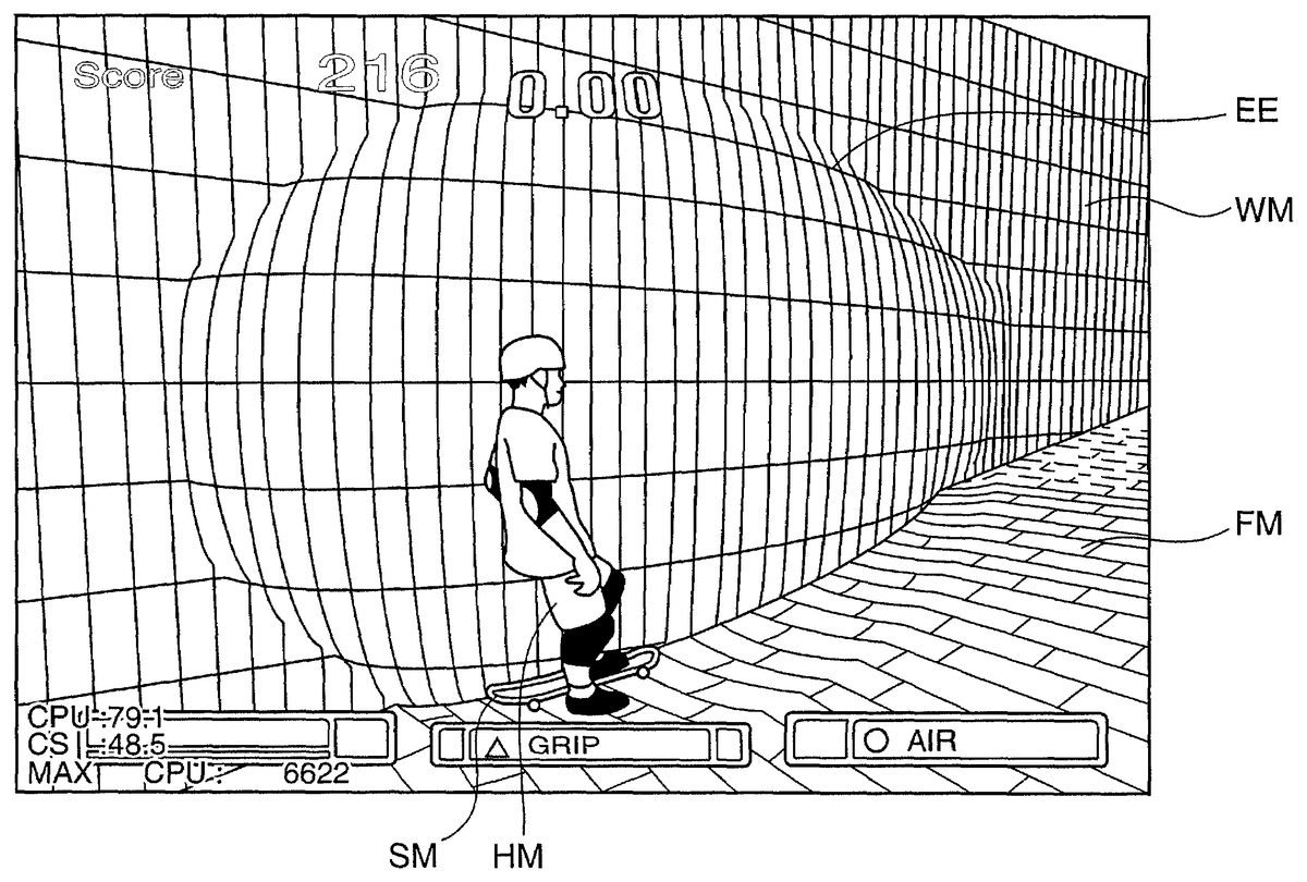
FIG. 5is a drawing of an screen obtained by performing the 3-D image processing of this invention on the original image shown inFIG. 8. In this aspect, the first original image and second original image are the same image, shown inFIG. 8. InFIG. 8, a wall model WM with a lattice-shape pattern, a floor model FM with a brick pattern, and a human model HM, with one foot resting on a skateboard model SM, are drawn. The image shown inFIG. 5comprises a large screen region MSC, displaying the second original image, and a small screen region SSC, displaying a deformed image obtained from the first original image. In this way, by displaying the original image in the large screen region MSC and a deformed image in the small screen region SSC, an image with a heightened sense of presence is obtained.
For the purpose of comparison with a screen display of a deformed image obtained by the conventional method and shown inFIG. 9,FIG. 6shows a full-screen view of the deformed image of the first original image displayed in the small screen region SSC ofFIG. 5, displayed on the entire screen. As explained above, in the deformed image ofFIG. 9obtained by the conventional method, in the vicinity of the outer border EE of the fisheye region, the image is unnaturally distorted, and straight lines in the original image are deformed into broken-line shapes to form an unnatural image. On the other hand, in the deformed image obtained by the method of this invention and shown inFIG. 6, even in the vicinity of the outer border EE of the fisheye region straight lines are deformed into curves, and a natural-looking image is obtained.
The present invention can take the following aspects.
(A) In this aspect of the invention, the case in which the first original image and second original image are the same image was explained; however, these may also be two original images taken from different camera viewpoints. In this case, it appears that images photographed from two different cameras are displayed, heightening the sense of presence.
(B) In this aspect of the invention, the case in which a deformed image is displayed in a small screen region, and an original image is displayed in a large screen region, was explained; however, the deformed image may be displayed in the large screen region, and the original image in the small screen region. Or, the former and the latter may be switched, according to the game progress. In the latter case, images rich in changes are drawn, heightening interest in the game.
(C) In this aspect of the invention, the case in which a 3-D model onto which an image has been pasted is not deformed (or, is deformed in advance) was explained; however, the 3-D model may be deformed according to the game progress. In this case, images rich in changes are drawn, heightening interest in the game.
(D) In this aspect of the invention, the case in which a composite image is drawn, formed by combining a deformed image and an original image into an image on a single screen, was explained; however, a deformed image alone may be drawn on a single screen. In this case, as it becomes possible to reduce the amount of memory required, processing becomes simpler.
(E) In this aspect of the invention, the case in which a 3-D model, onto which an image is pasted, has the shape of a plane having a rectangular outer perimeter and a curved surface formed by cutting the curved surface of an ellipsoid of revolution by the above plane, was explained; but any arbitrary shape in which at least a portion of a plane is distorted may be used. Because the deformed image is deformed according to the shape of the 3-D model, a shape may be selected from which a desired deformed image is obtained.
The 3-D image processing program of this invention is, for example, stored in advance in the recording medium200, is transferred from the recording medium200to main memory5, and processing is executed by the drawing processor10based on program data stored in main memory5.
In summary, the present invention relates to a computer readable recording medium storing a 3-D image processing program, which intentionally distorts an original image to generate a deformed image on a display screen. The 3-D image processing program comprises the steps of: storing an original image and a 3-D model comprising a plurality of polygons and having a shape in which at least a portion of a plane is distorted in 3-D space; performing image pasting processing, in which the original image is read and is pasted, as a texture, onto said 3-D model; and performing deformed image drawing processing, in which a deformed image, which is an image of said 3-D model onto which the original image has been pasted, as seen from a prescribed camera viewpoint, is drawn on a display screen.
The present invention relates also to a 3-D image processing method, which intentionally distorts an original image to generate a deformed image on a display screen. The method comprises the steps of: storing an original image and a 3-D polygon model comprising a plurality of polygons and having a shape in which at least a portion of a plane is distorted in 3-D space; reading the original image and pasting the same, as a texture, onto said 3-D polygon model; and drawing a deformed image, which is an image of said 3-D polygon model onto which the original image has been pasted, as seen from a prescribed camera viewpoint, on a display screen.
The present invention also relates to a 3-D image processing device, which intentionally distorts an original image to generate a deformed image on a display screen, comprising: original image storage means for storing an original image; model storage means for storing a 3-D model comprising a plurality of polygons, having a shape in which at least a portion of a plane is distorted in 3-D space; image pasting means for reading an original image from said original image storage means and pasting the image, as a texture, onto said 3-D model; and deformed image drawing means for drawing on a display screen, a deformed image which is an image of said 3-D model, onto which the original image has been pasted, as seen from a prescribed camera viewpoint.
In the above-described invention, an original image and a 3-D polygon model, comprising a plurality of polygons and having a shape in which at least a portion of a plane is distorted in 3-D space, are stored; the original image is read out and textured, and is pasted onto the polygon model, and an image of the polygon model onto which the original image is pasted, and which is seen from a prescribed camera viewpoint, is drawn on a display screen, to obtain a natural-looking deformed image as a result of intentional distortion of the original image.
In the invention as described in the above, an original image, and a 3-D polygon model comprising a plurality of polygons and having a shape in which at least a portion of a plane is distorted in 3-D space are stored; the original image is read, and is pasted as a texture onto the polygon model; and an image of the polygon model onto which the original image has been pasted, as seen from a prescribed camera viewpoint, is drawn on a display screen, so that a natural-looking deformed image, in which the original image has been intentionally distorted, is obtained.
In the computer readable recording medium, wherein said 3-D model preferably has a shape in which a plane, having a rectangular outer perimeter, is joined with a curved surface obtained by cutting the curved surface of an ellipsoid of revolution by said plane. In the above invention, because the 3-D model has the shape of a plane having a rectangular outer perimeter joined to a curved surface which is an ellipsoid of revolution cut by the above plane, using deformed image drawing means, the portion of an image pasted onto the curved surface of the ellipsoid of revolution becomes a deformed image, deformed in the manner of an image photographed through a fisheye lens. In the invention as described, the 3-D model has a shape obtained by joining a plane having a rectangular outer perimeter, and a curved surface formed by cutting the curved surface of an ellipsoid of revolution by the above plane; consequently from the portion of the image pasted onto the curved surface of the ellipsoid of revolution is obtained, through deformed image drawing means, a deformed image, which is deformed in the manner of an image photographed through a fisheye lens.
In the computer readable recording medium, wherein model deformation processing is performed in which said 3-D model is deformed by expansion or contraction of the curved surface of said ellipsoid of revolution in the direction perpendicular to said plane. In the above invention, the curved surface of the ellipsoid of revolution is expanded and contracted in the direction perpendicular to the plane during model deformation processing, and the 3-D model is deformed, so that from the portion of the image pasted onto the curved surface of the ellipsoid of revolution, a deformed image with different extents of deformation, similar to the image deformation of an image which has been photographed through fisheye lenses with various extents of deformation, can easily be obtained. In the invention as described, in model deformation processing the curved surface of the ellipsoid of revolution is expanded and contracted in the direction perpendicular to the plane, deforming the 3-D model; hence from the portion of the image which is pasted onto the curved surface of the ellipsoid of revolution, a deformed image can easily be obtained with various extents of deformation, similar to images photographed through fisheye lenses with various extents of deformation.
In the computer readable recording medium, wherein said prescribed camera viewpoint is situated on a straight line perpendicular to the plane comprised by said 3-D model, and passing through the approximate center of the plane. In the above invention, because the camera viewpoint is on a line perpendicular to the plane and passing through the approximate center of the plane comprised by the 3-D model, a naturally deformed image is obtained, similar to an image photographed through a fisheye lens from a camera viewpoint on the axis of the fisheye lens. In the invention as described, the camera viewpoint3is situated on a straight line which is perpendicular to the plane and passes through the approximate center of the plane comprised by the three-D model, so that a natural-looking deformed image, similar to an image photographed through a fisheye lens from a camera viewpoint on the axis of the fisheye lens, can be obtained.
In the computer readable recording medium, wherein said 3-D image processing program further comprising the steps of storing said deformed image, drawn by said deformed image drawing processing; performing image composition processing in which an original image and the deformed image are read, and an image is composed on a single screen; and performing composite image drawing processing in which a composite image composed by said image composition processing is drawn on a display screen. In the above invention, because a composite image formed by composing the original image and a deformed image is drawn on the display screen, the sense of presence is heightened. In the invention as described, a composite image formed by combining an original image and a deformed image is drawn on a display screen, so that the sense of presence is heightened.
In the computer readable recording medium, wherein in the storing processing, a first original image and a second original image, which are two original images taken from different camera viewpoints, are stored; a deformed image of the first original image is stored; and, in said image composition processing, the second original image and the deformed image are combined. In the above invention, of the two original images taken from different camera viewpoints, a composite image, obtained by composition of a deformed image of one of the original images and the other original image, is drawn on the display screen, so that the drawn composite image appears to have been photographed by two cameras, and the sense of presence is further heightened. In the invention, of two original images taken from different camera viewpoints, a composite image is created by combining one of the original images and a deformed image of the other original image, and is drawn on a display screen; consequently the drawn composite image appears to have been photographed by two cameras, and the sense of presence is further heightened.
The present invention takes also a form of a video game device, which comprise: a 3-D image processing device, which intentionally distorts an original image to generate a deformed image on a display screen, including original image storage means for storing an original image, model storage means for storing a 3-D model comprising a plurality of polygons, having a shape in which at least a portion of a plane is distorted in 3-D space, image pasting means for reading an original image from said original image storage means and pasting the image, as a texture, onto said 3-D model, and deformed image drawing means for drawing on a display screen, a deformed image which is an image of said 3-D model, onto which the original image has been pasted, as seen from a prescribed camera viewpoint; image display means for displaying images; program storage means for storing game program data; and operation means, enabling operation from outside; wherein said 3-D image processing device displays images on the image display means according to said game program data. By means of the above invention, a video game device is realized in which, by means of the 3-D image processing device, a natural-looking deformed image is obtained as a result of intentional distortion of an original image, and the deformed image is displayed on the image display means according to game program data recorded by the program storage means. In the invention as described, a natural-looking deformed image in which an original image is intentionally distorted is obtained by means of a 3-D image processing device, and a video game device is realized in which a deformed image is displayed by image display means according to game program data recorded in program storage means.
This application is based on Japanese patent application serial no. 2001-106991, filed in Japan Patent Office on Apr. 5, 2001, the contents of which are hereby incorporated by reference.
Although the present invention has been fully described by way of example with reference to the accompanying drawings, it is to be understood that various changes and modifications will be apparent to those skilled in the art. Therefore, unless otherwise such changes and modifications depart from the scope of the present invention hereinafter defined, they should be construed as being included therein.
Claims
- A computer readable recording medium storing an executable 3-D image processing program, which intentionally distorts an original image to generate a deformed image on a display screen, said 3-D image processing program comprising the steps of: storing an original image;storing a 3-D model comprising a plurality of polygons defining a shape including a plane in which a portion of said plane is distorted in 3-D space by a curved surface protruding therefrom, wherein the plane is bounded by a rectangular outer perimeter, and the curved surface is defined by said plane cutting through a volume defined by a rotation of an ellipsoid;performing image pasting processing, in which the original image is read and is pasted, as a texture, onto said 3-D model to form a composite image;and performing deformed image drawing processing including: deforming the composite image in accordance with viewing the 3-D model with the original image pasted thereon from a prescribed camera viewpoint;and drawing said deformed composite image on a display screen.
- The computer readable recording medium according to claim 1 , wherein model deformation processing is performed in which said 3-D model is deformed by expansion or contraction of the curved surface of said ellipsoid of revolution in the direction perpendicular to said plane.
- The computer readable recording medium according to claim 1 , wherein said prescribed camera viewpoint is situated on a straight line perpendicular to the plane comprised by said 3-D model, and passing through the approximate center of the plane.
- The computer readable recording medium according to claim 1 , wherein said 3-D image processing program further comprising the steps of: storing said deformed image, drawn by said deformed image drawing processing;performing image composition processing in which an original image and the deformed image are read, and an image including the original image in a major image area and said deformed image in a minor image area, smaller than said major image area, is composed on a single screen;and performing composite image drawing processing in which a composite image composed by said image composition processing is drawn on a display screen.
- The computer readable recording medium according to claim 4 , wherein: in the storing processing, a first original image and a second original image, which are two original images taken from different camera viewpoints, are stored;a deformed image of the first original image is stored;and, in said image composition processing, the second original image and the deformed image are combined.
- A 3-D image processing method, which intentionally distorts an original image to generate a deformed image on a display screen, said method comprising the steps of: storing an original image;storing a 3-D polygon model comprising a plurality of polygons defining a shape including a plane in which a portion of plane is distorted in 3-D space by a curved surface protruding therefrom, wherein the plane is bounded by a rectangular outer perimeter, and the curved surface is defined by said plane cutting through a volume defined by a rotation of an ellipsoid;reading the original image and pasting the same, as a texture, onto said 3-D polygon model to form a composite image;deforming the composite image in accordance with viewing the 3-D model with the original image pasted thereon from a prescribed camera viewpoint;and drawing said deformed composite image on a display screen.
- A 3-D image processing device, which intentionally distorts an original image to generate a deformed image on a display screen, comprising: original image storage means for storing an original image;model storage means for storing a 3-D model comprising a plurality of polygons defining a shape including a plane in which a portion of said plane is distorted in 3-D space by a curved surface protruding therefrom, wherein the plane is bounded by a rectangular outer perimeter, and the curved surface is defined by said plane cutting through a volume defined by a rotation of an ellipsoid;image pasting means for reading an original image from said original image storage means and pasting the image, as a texture, onto said 3-D model to form a composite image;deforming means for deforming the composite image in accordance with viewing the 3-D model with the original image pasted thereon from a prescribed camera viewpoint;and drawing means for drawing said deformed composite image on a display screen.
- A video game device, comprising: a 3-D image processing device, which intentionally distorts an original image to generate a deformed image on a display screen, including: original image storage means for storing an original image;model storage means for storing a 3-D model comprising a plurality of polygons defining a shape including a plane in which a portion of said plane is distorted in 3-D space by a curved surface protruding therefrom, wherein the plane is bounded by a rectangular outer perimeter, and the curved surface is defined by said plane cutting through a volume defined by a rotation of an ellipsoid;image pasting means for reading an original image from said original image storage means and pasting the image, as a texture, onto said 3-D model to form a composite image;deforming means for deforming the composite image in accordance with viewing the 3-D model with the original image pasted thereon from a prescribed camera viewpoint;image display means for displaying images;drawing means for drawing said deformed composite image on said image display means;program storage means for storing game program data;and, operation means, enabling operation from outside;wherein said 3-D image processing device displays images on the image display means according to said game program data.
- A computer readable recording medium storing an executable 3-D image processing program, which intentionally distorts an original image to generate a deformed image on a display screen, said program comprising the steps of: storing an original image;storing a 3-D model comprising a plurally of polygons defining a shape including a plane in which a portion of said plane is distorted in 3-D space by a curved surface protruding therefrom, wherein the plane is bounded by a rectangular outer perimeter, and the curved surface is defined by said plane cutting through a volume defined by a rotation of an ellipsoid;performing image pasting processing, in which the original image is read and is pasted, as a texture, onto said 3-D model to form a composite image;and, performing deformed image drawing processing including: deforming the composite image in accordance with viewing the 3-D model with the original image pasted thereon from a prescribed camera viewpoint;and drawing said deformed composite image on a display screen.
- A computer readable recording medium storing a 3-D image processing program, which intentionally distorts an original image to generate a deformed image on a display screen, said 3-D image processing program comprising the steps of: storing an original image;storing a 3-D model comprising a plurality of polygons defining a shape including a plane in which a portion of said plane is distorted in 3-D space by a curved surface protruding therefrom, wherein the plane is bounded by a rectangular outer perimeter, and the curved surface is defined by said plane cutting through a volume defined by a rotation of an ellipsoid;said portion being projected from a remainder of said plane from said plane towards a prescribed camera viewpoint;performing image pasting processing in which the original image is read and is pasted as a texture onto said 3-D model to form a composite image;and performing deformed image drawing processing including: deforming the composite image in accordance with viewing the 3-D model with the original image pasted thereon from a prescribed camera viewpoint;and drawing said deformed composite image on a display screen.
- A computer readable recording medium storing an executable 3-D image processing program, which intentionally distorts an original image to generate a deformed image on a display screen, said 3-D image processing program comprising the steps of: storing an original image;storing a 3-D model comprising a plurality of polygons defining a shape including a plane in which a portion of said plane is distorted in 3-D space by a curved surface protruding therefrom, wherein the plane is hounded by a rectangular outer perimeter, and the curved surface is defined by said plane cutting through a volume defined by a rotation of an ellipsoid;performing image pasting processing, in which the original image is read and is pasted, as a texture, onto said 3-D model to form a composite image wherein the 3-D model is formed such that the composite image appears as a fisheye view of the original image in a portion corresponding to said at least a portion of said plane;and performing deformed image drawing processing including: deforming the composite image in accordance with viewing the 3-D model with the original image pasted thereon from a prescribed camera viewpoint;and drawing said deformed composite image on a display screen.
Disclaimer: Data collected from the USPTO and may be malformed, incomplete, and/or otherwise inaccurate.