U.S. Pat. No. 7,027,034
METHOD OF MOVING OBJECTS ON TV MONITOR, THE COMPUTER AND RECORDING MEDIUM FOR EXECUTING THE METHOD
AssigneeSony
Issue DateJanuary 10, 2001
U.S. Patent No. 7,027,034: Method of moving objects on TV monitor, the computer and recording medium for executing the method

Summary:
The ‘034 patent describes a process whereby a control (having one or more pressure-sensitive means) moves an object determined by an output value of the controller which indicated a pressure exerted on the button by the player. The player presses one of the pressure-sensitive buttons on the controller and depending on how hard or how long the button is pressed, a certain action is performed by the animated character.
Abstract:
The movement of an object due to the continuous pushing of a simple ON/OFF switch is made an easier-to-use interface for users by a method of moving an object displayed on a screen of a TV monitor of a computer having a controller which has a pressure-sensitive unit. In the method, the pushing by a user on the controller is sensed by the pressure-sensitive unit, a pressure-sensing output signal is determined depending on the pushing pressure, and the object is moved within the screen of the TV monitor depending on the magnitude of the pressure-sensing output signal of the controller.
Illustrative Claim:
1. A recording medium on which is recorded a computer-readable and executable software program that performs processing by taking as instructions an output from a controller of a computer, said controller having one or more pressure-sensitive means, wherein said software program comprises a processing program that moves an object within a screen of a monitor of the computer depending on the output of said controller, wherein a distance moved by the object is determined by an output value of said controller indicative of a highest pushing pressure exerted on at least one of said one or more pressure-sensitive means during a current operating cycle of said one or more pressure-sensitive means, wherein the movement of the object within the screen of the monitor represents an action executed in a three-dimensional space; and wherein a distance of the movement of said object on the screen of the monitor is determined depending on a rate of change per unit time of the output value of said controller.
Illustrative Figure
Abstract
The movement of an object due to the continuous pushing of a simple ON/OFF switch is made an easier-to-use interface for users by a method of moving an object displayed on a screen of a TV monitor of a computer having a controller which has a pressure-sensitive unit. In the method, the pushing by a user on the controller is sensed by the pressure-sensitive unit, a pressure-sensing output signal is determined depending on the pushing pressure, and the object is moved within the screen of the TV monitor depending on the magnitude of the pressure-sensing output signal of the controller.
Description
DETAILED DESCRIPTION OF THE PREFERRED EMBODIMENTS Here follows a description of an embodiment of the method of moving objects at a movement velocity depending on the value of a pressure-sense value, and computer and recording medium for executing same according to the present invention, in detail with reference to the appended drawings. In this embodiment, objects are moved at a movement velocity depending on the value of a pressure-sense value, so it is possible to provide a system with a user interface that is improved in comparison to a system wherein objects are moved at a set velocity based on the pushing of a simple ON/OFF switch or the continuous pushing thereof. FIG. 1is a schematic diagram showing the connection of an entertainment system500to a TV monitor408, to enable a user to enjoy game software or video. More specifically the connection is shown in FIG.6. As shown in thisFIG. 1, a controller200which has buttons connected to pressure-sensitive devices inside the controller, is connected to the entertainment system500used for playing games or enjoying DVD video or other types of video images, and the video output terminals are connected to the television monitor408. Here, the analog output from the pressure-sensitive devices is converted by an A/D converter to digital values in the range 0-255 and provided to the entertainment system500. With reference toFIGS. 2-5, the way of the setting of the object movement velocity performed depending on the pressure-sensed value will be now described. It is assumed that the buttons used by a user for movement of images are mounted on a controller200, with one each for the left, right, up, down, forward and backward directions, and each of these six buttons being connected to pressure-sensitive devices. In addition, regarding left, right, forward and backward, by means of the directional keys known ...
DETAILED DESCRIPTION OF THE PREFERRED EMBODIMENTS
Here follows a description of an embodiment of the method of moving objects at a movement velocity depending on the value of a pressure-sense value, and computer and recording medium for executing same according to the present invention, in detail with reference to the appended drawings.
In this embodiment, objects are moved at a movement velocity depending on the value of a pressure-sense value, so it is possible to provide a system with a user interface that is improved in comparison to a system wherein objects are moved at a set velocity based on the pushing of a simple ON/OFF switch or the continuous pushing thereof.
FIG. 1is a schematic diagram showing the connection of an entertainment system500to a TV monitor408, to enable a user to enjoy game software or video. More specifically the connection is shown in FIG.6.
As shown in thisFIG. 1, a controller200which has buttons connected to pressure-sensitive devices inside the controller, is connected to the entertainment system500used for playing games or enjoying DVD video or other types of video images, and the video output terminals are connected to the television monitor408.
Here, the analog output from the pressure-sensitive devices is converted by an A/D converter to digital values in the range 0-255 and provided to the entertainment system500.
With reference toFIGS. 2-5, the way of the setting of the object movement velocity performed depending on the pressure-sensed value will be now described. It is assumed that the buttons used by a user for movement of images are mounted on a controller200, with one each for the left, right, up, down, forward and backward directions, and each of these six buttons being connected to pressure-sensitive devices. In addition, regarding left, right, forward and backward, by means of the directional keys known as the so-called cruciform keys to be described later, for example, it is possible to push the forward button and left button simultaneously, push the left button and backward button simultaneously, push the backward button and right button simultaneously, and also push the right button and forward button simultaneously. Moreover, regarding up and down movements, individual buttons are provided separately, so by pushing the up button the object can be made to move upward or jump up, and by pushing the down button the object can be made to move downward or jump down.
FIG. 2Ashows a three-dimensional space S prepared in advance. This three-dimensional space S is defined entirely with x, y and z three-dimensional coordinate values, where z0is the closest to the point of view of the user and zwis the farthest away from the point of view of the user. In addition, the frame at the position P0(300(x), 600(y), 0(z)) and the frame at P100(300(x), 600(y), 100(z)) are regions corresponding to the position of an object and these regions are displayed on the television monitor408. These two frames illustrated as an example have the first frame being the frame closest to the point of view and the next frame being a frame displaced from the point of view by 100 in the z direction.
An example of displaying the first frame P0is shown inFIG. 2B, while an example of displaying the next frame P100is shown in FIG.2C. As is evident from comparing these display examples2B and C, one can see that the latter frame appears to be closer to the mountains and sun defined to be farthest back inFIG. 2A, by the amount of the z value. This can be readily discerned by comparing the relationship between the object OB and the background BG0appearing in the first frame P0against that of the object OB and the background BG100appearing in the next frame P100.
FIG. 3shows an example of an image when the object OB is made to move upward or jump up. Starting from the state wherein the object OB is as inFIG. 3A, a jump is started as inFIG. 3B, and as shown inFIG. 3C, after reaching the apex (highest point) which depends on the strength of the jump, or namely depending on the velocity which depends on the value of the pressure-sense value from the controller, the object falls as shown in FIG.3D and lands.
In this manner, the coordinates of the destination (highest point) of movement of an object OB are found by taking a velocity coefficient E which depends on the values of various pressure-sense values output due to the pushing of the buttons allocated to left, right, up, down, forward and backward and multiplying by the current position. The coordinates of the current position Pn(x, y, z) of the object OB are each multiplied by the velocity coefficient E to find the next position Pn+1(xE, yE, zE). Then, the image corresponding to these coordinate values is rendered and displayed. In this manner, the greater the pressure-sense value, the object OB is moved farther and thus moves quicker, and conversely, the lesser the pressure-sense value, the object OB is not moved as far and thus moves less rapidly.
Naturally, the velocity coefficient may also be applied to x, y and z. In addition, the various coefficients E which depend on the pressure-sense value are all stored during the period of the jump until the apex is reached. After the apex is reached, the stored coefficients are reversed and change the position of the object gradually. Thereby, even if the user releases the button after the jump, the fall will still be smooth.
FIG. 4Ashows a table wherein velocity coefficients E1-E255are defined depending on pressure-sense values in the case of moving an object. The velocity coefficient is 1 when the pressure-sense value is in the range 0-5, so there is no movement of the object in this case and thus the same image is displayed. The velocity coefficients E1-E255are each allocated to pressure-sense values 6-255, respectively.
FIG. 4Bshows a table wherein velocity coefficients F1-F255are defined depending on pressure-sense values in the case of causing an object to jump. The velocity coefficient is 1 when the pressure-sensed value is in the range 0-5, so there is no movement of the object in this case and thus the same image is displayed. The velocity coefficients F1-F255are each allocated to pressure-sensed values 6-255, respectively.
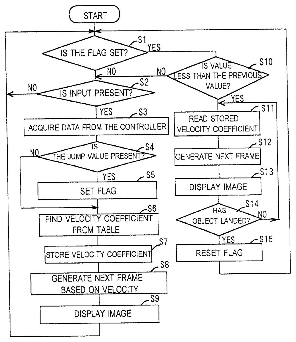
Next, with reference toFIG. 5, the movement process for an object will be described.FIG. 5is a flowchart for a program for performing the objects image movement process. This program may be supplied either recorded alone upon an optical disc or other recording medium, or recorded upon said recording medium together with the game software as part of the game software. This program is run by the entertainment system500and executed by its CPU.
The meaning of supplying these programs recorded individually on a recording medium has the meaning of preparing them in advance as a library for software development.
As is common knowledge, at the time of developing software, writing all functions requires an enormous amount of time. However, if the software functions are divided into single functions, for example, for moving objects and the like, they can be used commonly by various types of software, so more functions can be included.
To this end, a function such as that described in this preferred embodiment that can be used commonly may be provided to the software manufacturer side as a library program. When general functions like this are supplied as external programs in this manner, it is sufficient for the software manufacturers to write only the essential portions of the software.
In Step S1, a decision is made as to whether or not a jump flag used to indicate a jump is set, and if “YES” then control moves to Step S9, but if “NO” then control moves to Step S2.
In Step S2, a decision is made as to whether or not input is present, and if “YES” then control moves to Step S3where a pressure-sense value is acquired from the controller200.
Next, moving to Step S4, a decision is made as to whether or not a value corresponding to a jump is present, and if “YES” then control moves to Step S5where the jump flag is set, but if “NO” then control moves to Step S6and the velocity coefficients E each depending on the various pressure-sense values for left, right, forward and backward are found based on the table shown in FIG.4A.
Next, in Step S7, the velocity coefficients found in Step S6are stored. Next, in Step S8, each of the coordinates of the current position Pn(x, y, z) are multiplied sequentially by the velocity coefficients E for left, right, forward and backward to find the coordinate values for the next position. Note that x is multiplied by the left/right velocity coefficient E, y is multiplied by the up/down velocity coefficient E, and z is multiplied by the forward/backward velocity coefficient E.
Then, the individual apex coordinate values for the object are corrected based on the coordinate values of the next frame, and based on light-source calculations, the intensity of pixels at the apex indicated by various coordinate values are set, and next the apex coordinate values of the object are subjected to perspective transformation and transformed into two-dimensional coordinate values, texture data is mapped to the region indicated by these two-dimensional coordinate values, and the rendering process is performed to generate one frame of the image.
In Step S9, the aforementioned one frame of the image is displayed on the television monitor408.
It is to be noted that in the movement of an object upon a two-dimensional plane, x and y are multiplied by velocity coefficients E found from pressure-sense values corresponding to the up and right directional keys, left and down directional keys, down and right directional keys, or right and up directional keys, respectively.
In Step S10, a decision is made as to whether or not the value which is current, is less than the previous value and if the response is “YES” then the control procedure moves to Step S11, but if “NO” then the control procedure moves back to Step S2. This Step S10is where a decision is made as to whether the apex of the jump has been reached, namely whether or not to go to the falling process after the apex is reached.
In Step S11, the falling calculations are performed depending on the velocity coefficients during falling. In the same manner as the multiplication already described, these are performed by multiplying the y coordinate value of the current position Pn(x, y, z) by the velocity coefficient. It should be noted that in the case wherein the jump angle is not a vertical 90°, then it is sufficient to find various coefficients for x, for y and for z from the jump to the landing place depending on the angle, and multiply the current position Pn(x, y, z) by these coefficients.
In Step S12, one frame of the image is generated, and in Step S13it is displayed on the television monitor408.
In Step S14, a decision as to whether or not the object has landed is made based on the coordinate values thus found, and if “YES” then the flag is reset in Step S15and control procedure moves back to Step S1, but if “NO” then the control procedure moves to Step S11.
It is to be noted that it is also possible to find the percent change from the previous pressure-sense value to the current pressure-sense value, and find the next position by means of a velocity coefficient that depends on this percent change. For example, if the previous pressure-sensed value is 100 and the current pressure-sensed value is 50, then the percent change is 50%, so the velocity coefficient used may be a velocity coefficient ½ the maximum velocity coefficient if initial or if not initial, a velocity coefficient ½ the velocity coefficient used immediately before may be used. By doing so, it is possible to make the character move smoothly or perform jumps or other actions depending on the strength with which the user pushes the button.
FIG. 6is a diagram showing the controller200connected to entertainment system500. The controller200is removably connected to the entertainment system500, and the entertainment system500is connected to television monitor408.
The entertainment system500reads the program for a computer game from recording media upon which that program is recorded and by executing the program, displays characters on the television monitor408. The entertainment system500has also various built-in functions for DVD (Digital Versatile Disc) playback, CDDA (compact disc digital audio) playback and the like. The signals from the controller200are also processed as one of the aforementioned control functions within the entertainment system500, and the content thereof may be reflected in the movement of characters and the like, on the television monitor408.
While this depends also on the content of the computer game program, controller200may be allocated functions for moving the characters display on the television monitor408in the directions up, down, left or right.
With reference toFIG. 7, here follows a description of the interior of the entertainment system500shown in FIG.6.FIG. 7is a block diagram of the entertainment system500.
A CPU401is connected to RAM402and a bus403, respectively. Connected to bus403are a graphics processor unit (GPU)404and an input/output processor (I/O)409, respectively. The GPU404is connected via an encoder407for converting a digital RGB signal or the like into the NTSC standard television format, for example, to a television monitor (TV)408as a peripheral. Connected to the I/O409are a driver (DRV)410used for the playback and decoding of data recorded upon an optical disc411, a sound processor (SP)412, an external memory415consisting of flash memory, controller200and a ROM416which records the operating system and the like. The SP412is connected via an amplifier413to a speaker414as a peripheral.
Here, the external memory415may be a card-type memory consisting of a CPU or a gate array and flash memory, which is removably connected via a connector511to the entertainment system500shown in FIG.6.
The controller200is configured such that, when a plurality of buttons provided thereupon are pushed, it gives instructions to the entertainment system500. In addition, the driver410is provided with a decoder for decoding images encoded based upon the MPEG standard.
The description will be made now as to how the images will be displayed on the television monitor408based on the operation of controller200. It is assumed that data for objects consisting of polygon vertex data, texture data and the like recorded on the optical disc411is read by the driver410and stored in the RAM402of the CPU401.
When instructions from the player via controller200are provided as an input to the entertainment system500, the CPU401calculates the three-dimensional position and orientation of objects with respect to the point of view based on these instructions. Thereby, the polygon vertex data for objects defined by X, Y, Z coordinate values are modified variously. The modified polygon vertex data is subjected to perspective conversion processing and converted into two-dimensional coordinate data.
The regions specified by two-dimensional coordinates are so-called polygons. The converted coordinate data, Z data and texture data are supplied to the GPU404. Based on this converted coordinate data, Z data and texture data, the GPU404performs the drawing process by writing texture data sequentially into the Ram405. One frame of image data upon which the drawing process is completed, is encoded by the encoder407and then supplied to the television monitor408and displayed on its screen as an image.
FIG. 8is a top view of controller200. The controller200consists of a unit body201on the top surface of which are provided first and second control parts210and220, and on the side surface of which are provided third and fourth control parts230and240of the controller200.
The first control part210of the controller is provided with a cruciform control unit211used for pushing control, and the individual control keys211aextending in each of the four directions of the control unit211form a control element. The first control part210is the control part for providing movement to the characters displayed on the screen of the television receiver, and has the functions for moving the characters in the up, down, left and right directions by pressing the individual control keys211aof the cruciform control unit211.
The second control part220is provided with four cylindrical control buttons221(control elements) for pushing control. The individual control buttons221have identifying marks such as “∘” (circle), “×” (cross), “Δ” (triangle), and “□” (quadrangle) on their tops, in order to easily identify the individual control buttons221. The functions of the second control part220are set by the game program recorded on the optical disc411, and the individual control buttons221may be allocated functions that change the state of the game characters, for example. For example, the control buttons221may be allocated the functions for moving the left arm, right arm, left leg and right leg of the character.
The third and fourth control parts230and240of the controller have nearly the same structure, and both are provided with two control buttons231and241(control elements) for pushing control, arranged above and below. The functions of these third and fourth control parts230and240are also set by the game program recorded upon the optical disc, and may be allocated functions for making the game characters do special actions, for example.
Moreover, two joy sticks251for performing analog operation are provided upon the unit body201shown in FIG.8. The joy sticks251can be switched and used instead of the first and second control parts210and220described above. This switching is performed by means of an analog selection switch252provided upon the unit body201. When the joy sticks251are selected, a display lamp253provided on the unit body201lights, indicating the state wherein the joy sticks251are selected.
It is to be noted that on unit body201there are also provided a start switch254for starting the game and a select switch255for selecting the degree of difficulty or the like at the start of a game, and the like. InFIG. 8, the controller200is held by the left hand and the right hand and is operated by the other fingers, and in particular the thumbs are able to operate most of the buttons on the top surface.
FIG.9andFIGS. 10A-10Care respectively an exploded perspective view and cross-sectional views showing the second control part of the controller.
As shown inFIG. 9, the second control part220consists of four control buttons221which serve as the control elements, an elastic body222, and a sheet member223provided with resistors40. The individual control buttons221are inserted from behind through insertion holes201a formed on the upper surface of the unit body201. The control buttons221inserted into the insertion holes201aare able to move freely in the axial direction.
The elastic body222is made of insulating rubber or the like and has elastic areas222awhich protrude upward, and the lower ends of the control buttons221are supported upon the upper walls of the elastic areas222a. When the control buttons221are pressed, the inclined-surface portions of these elastic areas222aflex so that the upper walls move together with the control buttons221. On the other hand, when the pushing pressure on the control buttons221is released, the flexed inclined-surface portions of elastic areas222aelastically return to their original shape, pushing up the control buttons221. The elastic body222functions as a spring means whereby control buttons221which had been pushed in by a pushing action are returned to their original positions. As shown inFIGS. 10A-10C, conducting members50are attached to the rear surface of the elastic body222.
The sheet member223consists of a membrane or other thin sheet material which has flexibility and insulating properties. Resistors40are provided in appropriate locations on this sheet member223and these resistors40and conducting member50are each disposed such that they face one of the control buttons221via the elastic body222. The resistors40and conducting members50form pressure-sensitive devices. These pressure-sensitive devices consisting of resistors40and conducting members50have resistance values that vary depending on the pushing pressure received form the control buttons221.
To describe this in more detail, as shown inFIGS. 10A-10C, the second control part220is provided with control buttons221as control elements, an elastic body222, conducting members50and resistors40. Each conducting member50may be made of conductive rubber which has elasticity, for example, and has a conical shape with its center as a vertex. The conducting members50are adhered to the inside of the top surface of the elastic areas222aformed in the elastic body222.
In addition, the resistors40may be provided on an internal board204, for example, opposite the conducting members50, so that the conducting members50come into contact with resistors40together with the pushing action of the control buttons221. The conducting member50deforms, depending on the pushing force on the control button221(namely the contact pressure with the resistor40), so as shown inFIGS. 10B and 10C, the surface area in contact with the resistor40varies depending on the pressure. To wit, when the pressing force on the control button221is weak, as shown inFIG. 10B, only the area near the conical tip of the conducting member50is in contact. As the pressing force on the control button221becomes stronger, the tip of the conducting member50deforms gradually so the surface area in contact expands.
FIG. 11is a diagram showing an equivalent circuit for a pressure-sensitive device consisting of a resistor40and conducting member50. As shown in this diagram, the pressure-sensitive device is inserted in series in a power supply line13, where the voltage Vccis applied between the electrodes40aand40b. As shown in this diagram, the pressure-sensitive device is divided into a variable resistor42that has the relatively small resistance value of the conducting member50, and a fixed resistor41that has the relatively large resistance value of the resistor40. Among these, the portion of the variable resistor42is equivalent to the portion of resistance in the contact between the resistor40and the conducting member50, so the resistance value of the pressure-sensitive device varies depending on the surface area of contact with the conducting member50.
When the conducting member50comes into contact with the resistor40, in the portion of contact, the conducting member50becomes a bridge instead of the resistor40and a current flows, so the resistance value becomes smaller in the portion of contact. Therefore, the greater the surface area of contact between the resistor40and conducting member50, the lower the resistance value of the pressure-sensitive device becomes. In this manner, the entire pressure-sensitive device can be understood to be a variable resistor. It is noted thatFIGS. 10A-10Cshow only the contact portion between the conducting member50and resistor40which forms the variable resistor42ofFIG. 11, but the fixed resistor ofFIG. 13is omitted form FIG.12.
In the preferred embodiment, an output terminal is provided near the boundary between the variable resistor42and fixed resistor41, namely near the intermediate point of the resistors40, and thus a voltage stepped down from the applied voltage Vccby the amount the variable resistance is extracted as an analog signal corresponding to the pushing pressure by the user on the control button221.
First, since a voltage is applied to the resistor40when the power is turned on, even if the control button221is not pressed, a fixed analog signal (voltage) Vminis provided as the output from the output terminal40c. Next, even if the control button221is pressed, the resistance value of this resistor40does not change until the conducting member50contacts the resistor40, so the output from the resistor40remains unchanged at Vmin.
If the control button221is pushed further and the conducting member50comes into contact with the resistor40, the surface area of contact between the conducting member50and the resistor40increases in response to the pushing pressure on the control button221, and thus the resistance of the resistor40is reduced so the analog signal (voltage) output from the output terminal40cof the resistor40increases. Furthermore, the analog signal (voltage) output form the output terminal40cof the resistor40reaches the maximum Vmaxwhen the conducting member50is most deformed.
FIG. 12is a block diagram showing the main parts of the controller200.
An MPU14mounted on the internal board of the controller200is provided with a switch18, an A/D converter16and two vibration generation systems. The analog signal (voltage) output from the output terminal40cof the resistor40is provided as the input to the A/D converter16and is converted to a digital signal.
The digital signal output from the A/D converter16is sent via an interface17provided upon the internal board of the controller200to the entertainment system500and the actions of game characters and the like are executed based on this digital signal.
Changes in the level of the analog signal output from the output terminal40cof the resistor40correspond to changes in the pushing pressure received form the control button221(control element) as described above. Therefore, the digital signal outputted from the A/D converter16corresponds to the pushing pressure on the control button221(control element) from the user. If the actions of the game characters and the like are controlled based on the digital signal that has such a relationship with the pushing pressure from the user, it is possible to achieve smoother and more analog-like action than with control based on a binary digital signal based only on zeroes and ones.
The configuration is such that the switch18is controlled by a control signal sent from the entertainment system500based on a game program recorded on an optical disc411. When a game program recorded on optical disc is executed by the entertainment system500, depending on the content of the game program, a control signal is provided as output to specify whether the A/D converter16is to function as a means of providing output of a multi-valued analog signal, or as a means of providing a binary digital signal. Based on this control signal, the switch18is switched to select the function of the A/D converter16.
FIGS. 13 and 14show an embodiment of the first control part of the controller.
As shown inFIG. 13, the first control part210includes a cruciform control unit211, a spacer212that positions this control unit211, and an elastic body213that elastically supports the control unit211. Moreover, as shown inFIG. 12, a conducting member50is attached to the rear surface of the elastic body213, and the configuration is such that resistors40are disposed at the positions facing the individual control keys211a(control elements) of the control unit211via the elastic body213.
The overall structure of the first control part210has already been made public knowledge in the publication of unexamined Japanese patent application No. JP-A-H8-163672. The control unit211uses a hemispherical projection212aformed in the center of the spacer212as a fulcrum, and the individual control keys211a(control elements) are assembled such that they can push on the resistor40side (see FIG.14).
Conducting members50are adhered to the inside of the top surface of the elastic body213in positions corresponding to the individual control keys211a(control elements) of the cruciform control unit211. In addition, the resistors40with a single structure are disposed such that they face the individual conducting members50.
When the individual control keys211awhich are control elements are pushed, the pushing pressure acts via the elastic body213on the pressure-sensitive devices consisting of a conducting member50and resistor40, so that its electrical resistance value varies depending on the magnitude of the pushing pressure.
FIG. 15is a diagram showing the circuit configuration of the resistor. As shown in this diagram, the resistor40is inserted in series in a power supply line13, where a voltage is applied between the electrodes40aand40b. The resistance of this resistor40is illustrated schematically, as shown in this diagram; the resistor40is divided into first and second variable resistors43and44.
Among these, the portion of the first variable resistor43is in contact, respectively, with the conducting member50that moves together with the control key (up directional key)211afor moving the character in the up direction, and with the conducting member50that moves together with the control key (left directional key)211afor moving the character in the left direction, so its resistance value varies depending on the surface area in contact with these conducting members50.
In addition, the portion of the second variable resistor44is in contact, respectively, with the conducting member50that moves together with the control key (down directional key)211afor moving the character in the down direction, and with the conducting member50that moves together with the control key (right directional Key)211afor moving the character in the right direction, so its resistance value varies depending on the surface area in contact with these conducting members50.
Moreover, an output terminal40cis provided intermediate between the variable resistors43and44, and an analog signal corresponding to the pushing pressure on the individual control keys211a(control elements) is providing as output from this output terminal40c.
The output from the output terminal40ccan be calculated from the ratio of the split in resistance value of the first and second variable resistors43and44. For example, if R1is the resistance value of the first variable resistor43, R2is the resistance value of the second variable resistor44and Vccis the power supply voltage, then the output voltage V appearing at the output terminal40ccan be expressed by the following equation.
V=Vcc×R2/(R1+R2)
Therefore, when the resistance value of the first variable resistor43decreases, the output voltage increases, but when the resistance value of the second variable resistor44decreases, the output voltage also decreases.
FIG. 16is a graph showing the characteristic of the analog signal (voltage) outputted from the output terminal of the resistor.
First, since a voltage is applied to the resistor40when the power is turned on, even if the individual control keys211aof the control unit211are not pressed, a fixed analog signal (voltage) V0is provided as output form the output terminal40c(at position 0 in the graph).
Next, even if one of the individual control keys221ais pressed, the resistance value of this resistor40does not change until the conducting member50contacts the resistor40, and the output from the resistor40remains unchanged at V0.
Furthermore, if the up-directional key or left-directional key is pushed until the conducting member50comes into contact with the first variable resistor43portion of the resistor40(at position p in the graph), thereafter the surfaced area of contact between the conducting member50and the first variable resistor43portion increases in response to the pushing pressure on the control key221a(control element), and thus the resistance of that portion is reduced so the analog signal (voltage) output from the output terminal40cof the resistor40increases. Furthermore, the analog signal (voltage) output form the output terminal40cof the resistor40reaches the maximum Vmaxwhen the conducting member50is most deformed (at position s in the graph).
On the other hand, if the down-directional key or right-directional key is pushed until the conducting member50comes into contact with the second variable resistor44portion of the resistor40(at position r in the graph), thereafter the surface area of contact between the conducting member50and the second variable resistor44portion increases in response to the pushing pressure on the control key211a(control element), and thus the resistance of that portion is reduced, and as a result, the analog signal (voltage) output from the output terminal40cof the resistor40decreases. Furthermore, the analog signal (voltage) output form the output terminal40cof the resistor40reaches the minimum Vminwhen the conducting member50is most deformed (at position q in the graph).
As shown inFIG. 17, the analog signal (voltage) output from the output terminal40cof the resistor40is provided as input to an A/D converter16and converted to a digital signal. Note that the function of the A/D converter16is shown inFIG. 17is as described previously based onFIG. 12, so a detailed description shall be omitted here.
FIG. 18is an exploded perspective view of the third control part of the controller.
The third control part230consists of two control buttons231, a spacer232for positioning these control buttons231within the interior of the controller200, a holder233that supports these control buttons231, an elastic body234and an internal board235, having a structure wherein resistors40are attached to appropriate locations upon the internal board235and conducting members50are attached to the rear surface of the elastic body234.
The overall structure of the third control part230also already has been made public knowledge in the publication of unexamined Japanese patent application No. JP-A-H8-163672. The individual control buttons231can be pushed in while being guided by the spacer232. The pushing pressure when buttons231are pressed acts via the elastic body234on the pressure-sensitive device consisting of a conducting member50and resistor40. The electrical resistance value of the pressure-sensitive device varies depending on the magnitude of the pushing pressure it receives.
It is noted that the fourth control part240shown inFIG. 8has the same structure as that of the third control part230described above.
While an embodiment was described above, the present invention may also assume the following alternative embodiment. In the above embodiment, the pressure-sensing value as pushed by the user is used as is. However, in order to correct for differences in the body weights of users or differences in how good their reflexes are, it is possible to correct the maximum value of the user pressure-sensing value to the maximum game pressure-sensing value set by the program, and intermediate values may be corrected proportionally and used. This type of correction is performed by preparing a correction table. In addition, the user pressure-sensing value can be corrected based upon a known function. Moreover, the maximum value of the user pressure-sensing value rate of change may be corrected to the maximum game pressure-sensing value rate of change set in the program, and intermediate values can be proportionally corrected and used. For more details about this method, refer to the present inventors' Japanese patent application No. 2000-40257 and the corresponding PCT application JP/(Applicant file reference No. SC00097).
As described above, in this embodiment, the object is moved at a velocity based on the pressure-sensing value, so the user interface can be improved.
Claims
- A recording medium on which is recorded a computer-readable and executable software program that performs processing by taking as instructions an output from a controller of a computer, said controller having one or more pressure-sensitive means, wherein said software program comprises a processing program that moves an object within a screen of a monitor of the computer depending on the output of said controller, wherein a distance moved by the object is determined by an output value of said controller indicative of a highest pushing pressure exerted on at least one of said one or more pressure-sensitive means during a current operating cycle of said one or more pressure-sensitive means, wherein the movement of the object within the screen of the monitor represents an action executed in a three-dimensional space;and wherein a distance of the movement of said object on the screen of the monitor is determined depending on a rate of change per unit time of the output value of said controller.
- The recording medium according to claim 1 , wherein the distance of the movement of the object is determined by multiplying a current position of said object by a rate of change coefficient correlated with the output value of said controller.
- The recording medium according to claim 1 , wherein the action executed in a three-dimensional space is a jumping action.
- A method of moving an object displayed on a screen of a monitor of a computer having a controller which has one or more pressure-sensitive means, comprising the steps of: sensing a pushing pressure exerted by a user on said controller of the computer by said one or more pressure-sensitive means;determining a pressure-sensing output signal depending on said sensed pressure;and moving the object within the screen depending on a magnitude of said pressure-sensing output signal, wherein the magnitude is indicative of a highest pushing pressure exerted on said pressure-sensitive means during a current operating cycle of said pressure-sensitive means and the movement of the object within the screen of the monitor represents an action executed in a three-dimensional space;wherein in said step of moving the object within the screen depending on the magnitude of said pressure-sensing output signal, a distance of movement of the object is determined depending on the rate of change per unit time of the magnitude of said pressure-sensing output signal.
- The method of moving an object according to claim 4 , wherein the action executed in a three-dimensional space is a jumping action.
- A method of moving an object displayed on a screen of a monitor of a computer having a controller which has one or more pressure-sensitive means, comprising the steps of: sensing a pushing pressure exerted by a user on said controller of the computer by said one or more pressure-sensitive means;determining a pressure-sensing output signal depending on said sensed pressure;and moving the object within the screen depending on a magnitude of said pressure-sensing output signal, wherein the magnitude is indicative of a highest pushing pressure exerted on said pressure-sensitive means during a current operating cycle of said pressure-sensitive means and the movement of the object within the screen of the monitor represents an action executed in a three-dimensional space;wherein in said step of moving said object within the screen depending on the magnitude of said pressure-Sensing output signal, a position of movement of said object is determined by multiplying a current position of said object by a velocity coefficient that depends on the magnitude of said pressure-sensing signal.
- A computer to which a monitor having a screen is interconnected, said computer comprising: a controller which has pressure-sensitive means;one or more means for sensing a pushing pressure exerted by a user on said controller;means for determining a pressure-sensing output signal depending on said pushing pressure;means for moving an object within said screen displayed on said monitor depending on a magnitude of said pressure-sensing output signal, wherein said means for sensing indicates a highest pushing pressure exerted on said one or more means for sensing a pushing pressure during a current operating cycle of said pressure-sensitive means and the movement of the object within said screen represents an action executed in a three-dimensional space;and means for determining a distance of movement of the object depending on a rate of change per unit time of the magnitude of said pressure-sensing output signal.
- The computer according to claim 7 , wherein said means for determining a distance of movement of the object multiplies a current position of said object by a rate of change coefficient correlated with the magnitude of said pressure-sensing output signal.
- The computer according to claim 7 , wherein the action executed in a three-dimensional space is a jumping action.
- A recording medium on which is recorded a computer-readable and executable software program that performs processing by taking as instructions an output from a controller of a computer, said controller having one or more pressure-sensitive means, wherein said software program comprises a processing program that moves an object within a screen of a monitor of the computer depending on the output of said controller, wherein a distance moved by the object is determined by an output value of said controller indicative of a highest pushing pressure exerted on at least one of said one or more pressure-sensitive means during a current operating cycle of said one or more pressure-sensitive means, wherein the movement of the object within the screen of the monitor represents an action executed in a three-dimensional space;and wherein a vertical distance of the movement of the object is determined depending on a rate of change per unit time of the output value of said controller by multiplying a current vertical position of said object by a rate of vertical change coefficient correlated with the output value of said controller, successive rate of vertical change coefficients being stored for manipulation to reverse the distance of vertical movement after a vertical apex of the object is reached.
- The recording medium according to claim 10 , wherein said software program determines that a vertical apex has been reached when a component of the pushing pressure exerted on said one or more pressure-sensitive means indicating the vertical distance of movement is released.
- A method of moving an object displayed on a screen of a monitor of a computer having a controller which has one or more pressure-sensitive means, comprising the steps of: sensing a pushing pressure exerted by a user on said controller of the computer by said one or more pressure-sensitive means;determining a pressure-sensing output signal depending on said sensed pressure;and moving the object within the screen depending on a magnitude of said pressure-sensing output signal, wherein the magnitude is indicative of a highest pushing pressure exerted on said pressure-sensitive means during a current operating cycle of said pressure-sensitive means and the movement of the object within the screen of the monitor represents an action executed in a three-dimensional space;wherein in said step of moving said object within the screen depending on the magnitude of said pressure-sensing output signal, a vertical position of movement of said object is determined by multiplying a current position of said object by a vertical velocity coefficient that depends on the magnitude of said pressure-sensing signal, successive vertical velocity coefficients are stored, and the stored vertical velocity coefficients are used to reverse the vertical position of movement after determining that a vertical apex of the object is reached.
- The recording medium according to claim 12 , wherein the vertical apex is determined to be reached when a component of the pushing pressure exerted on said one or more pressure-sensitive means indicating the vertical distance of movement is released.
- A computer to which a monitor having a screen is interconnected, said computer comprising: a controller which has pressure-sensitive means;one or more means for sensing a pushing pressure exerted by a user on said controller;means for determining a pressure-sensing output signal depending on said pushing pressure;means for moving an object within said screen displayed on said monitor depending on a magnitude of said pressure-sensing output signal, wherein said means for sensing indicates a highest pushing pressure exerted on said one or more means for sensing a pushing pressure during a current operating cycle of said pressure-sensitive means and the movement of the object within said screen represents an action executed in a three-dimensional space;and means for determining a vertical distance of movement of the object depending on a rate of change per unit time of the magnitude of said pressure-sensing output signal by multiplying a vertical position of said object by a vertical distance rate of change coefficient correlated with the magnitude of said pressure-sensing output signal, storing successively determined vertical distance rate of change coefficients, and reversing the vertical position by manipulating the stored vertical distance rate of change coefficients after a vertical apex of the object is reached.
- The computer according to claim 14 , wherein the vertical apex is determined to be reached when a component of the pushing pressure exerted on said one or more means for sensing a pushing pressure indicating the vertical distance of movement is released.
- A computer executing a software program that performs processing by taking as instructions an output from a controller of a computer, said controller having one or more pressure-sensitive means, wherein said software program comprises a processing program that moves an object within a screen of a monitor of the computer depending on the output of said controller, wherein a distance moved by the object is determined by an output value of said controller indicative of a highest pushing pressure exerted on at least one of said one or more pressure-sensitive means during a current operating cycle of said one or more pressure-sensitive means, wherein the movement of the object within the screen of the monitor represents an action executed in a three-dimensional space;and wherein a distance of the movement of said object on the screen of the monitor is determined depending on a rate of change per unit time of the output value of said controller.
Disclaimer: Data collected from the USPTO and may be malformed, incomplete, and/or otherwise inaccurate.