U.S. Pat. No. 7,014,562
VIDEO GAME MACHINE AND AFTER-IMAGE DISPLAY METHOD OF VIDEO GAME MACHINE
AssigneeNamco Ltd.
Issue DateMay 31, 2002
Illustrative Figure
Abstract
An after-image of a ball is displayed on traces of the ball so that each gamer recognizes in which direction and at which speed the shot ball flies. A real ball 30 really exists in a virtual space on a screen and flies from the left to the right in the figure. After-images 311 to 314 of the real ball 30 are displayed at the back of the real ball 30. The after-image 312 is displayed at a position of the real ball 30 before one interval (corresponding to 1/60 sec), the after-image 312 is displayed at a position of the real ball 30 before two intervals, the after-image 313 is displayed at a position of the real ball 30 before three intervals, and the after-image 314 is displayed at a position of the real ball 30 before four intervals. As the after-image is more apart from the real ball 30, the degree of transparency is higher.
Description
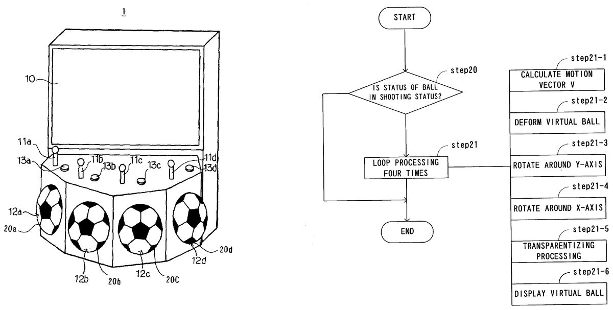
BEST MODE FOR CARRYING OUT THE INVENTION There will be described hereinafter the best mode for carrying out the invention according to the present application with reference to the drawings. Before description of a main portion of the present invention, the outline of a video game of a sport video game machine will be described with reference toFIGS. 1 and 2.FIG. 1is a perspective view showing the appearance of the overall sport video game machine, andFIG. 2is a cross-sectional view showing the structure of a kick input unit of the sport video game machine shown inFIG. 1. A sport video game machine1inFIG. 1is a video game machine of a game dedicated for simulating futsal as a sport which is small-scaled soccer. A team of a player character on a screen can be discriminated depending on a uniform wear. Each team contains five player characters and gamers operate four player characters except for a goal keeper. Hereinafter, the player character represented on a screen is simply referred to as a “player”. In the video game machine1inFIG. 1, maximum four gamers can play the video game. Each gamer operates the motion of one player in a field assigned thereto. If the number of the gamers is three or less, an operation of the player, which is not operated by the gamer, is controlled by a CPU in accordance with a predetermined algorithm. Incidentally, the CPU always controls a goal keeper. The video game machine1comprises a screen10for displaying a moving image or a still image of contents of the game and other necessary items at a position which is determined in consideration of the height of gamer's eye. During a play time of the game, in principle, an image in the field, which is displayed on the screen10, indicates an image when the ...
BEST MODE FOR CARRYING OUT THE INVENTION
There will be described hereinafter the best mode for carrying out the invention according to the present application with reference to the drawings.
Before description of a main portion of the present invention, the outline of a video game of a sport video game machine will be described with reference toFIGS. 1 and 2.FIG. 1is a perspective view showing the appearance of the overall sport video game machine, andFIG. 2is a cross-sectional view showing the structure of a kick input unit of the sport video game machine shown inFIG. 1.
A sport video game machine1inFIG. 1is a video game machine of a game dedicated for simulating futsal as a sport which is small-scaled soccer. A team of a player character on a screen can be discriminated depending on a uniform wear. Each team contains five player characters and gamers operate four player characters except for a goal keeper. Hereinafter, the player character represented on a screen is simply referred to as a “player”.
In the video game machine1inFIG. 1, maximum four gamers can play the video game. Each gamer operates the motion of one player in a field assigned thereto. If the number of the gamers is three or less, an operation of the player, which is not operated by the gamer, is controlled by a CPU in accordance with a predetermined algorithm. Incidentally, the CPU always controls a goal keeper.
The video game machine1comprises a screen10for displaying a moving image or a still image of contents of the game and other necessary items at a position which is determined in consideration of the height of gamer's eye. During a play time of the game, in principle, an image in the field, which is displayed on the screen10, indicates an image when the field is looked down in a oblique direction from the side.
An operating unit under the screen10comprises four operating panels a, b, c, and d in consideration of the case of a play operation of the four gamers. The operating panels a, b, c, and d have levers11(11a,11b,11c, and11d), kick input units12(12a,12b,12c, and12d), and buttons13(13a,13b,13c, and13d), respectively. Each gamer stands before his own operating panel and operates the lever11, the kick input unit12, and the button13.
When the operated player simply moves or keeps and dribbles a ball, instruction contents, which are operated by the lever11, include a moving direction or a moving speed of the player. When the operated player kicks the ball to pass or shoot the ball, the instruction contents include a fly direction of the kicked ball.
In the video game machine1, an analog lever is used as the lever11. In the analog lever, two volumes (an x-volume and a y-volume) having resistances changed depending the rotations of shafts thereof, are arranged so that the shafts are perpendicular to each other. The bottom of shaft of the lever11is connected to the shafts of the x-volume and the y-volume by a gear or the like. The shafts of the x-volume and the y-volume are rotated in accordance with an inclined direction of the lever11and an angle of inclination thereof. If the lever11is inclined in the x-axis direction or (−x)-axis direction (in the horizontal direction), only the x-volume is rotated. If the lever11is inclined in the y-axis direction or (−y)-direction (in the vertical direction), only the y-volume is rotated. Further, if the lever11is inclined in any direction other than the above-mentioned directions, both the x-volume and the y-volume are rotated corresponding to the amount of inclinations thereof. The CPU always detects the resistances of the x-volume and the y-volume at predetermined intervals, as will be described later. The CPU calculates vectors based on the resistances and recognizes the inclined angle and direction of the lever11. In accordance with continuous change in the inclined angle and inclined direction of the lever11, rotational angles of the shafts and the resistances of the x-volumes and the y-volume are continuously changed. Therefore, the CPU continuously recognizes the inclined direction and inclined angle.
The kick input unit12is provided at a lower portion of the video game machine1. Mainly, operations of the kick input unit12are instructions for starting operations such as pass, shoot and sliding tackle which are made by the operated player and speed control of the ball kicked through the pass and the shoot. The kick input unit12comprises a ball unit20for kicking the ball by gamer's foot like the actual futsal or soccer. The ball unit20is hemispherical with substantially the same dimension and pattern of an actual futsal ball. A material similar or substantially similar to the futsal ball is used as a material of the surface of the ball unit20.
As shown inFIG. 2, a stick shaft21is provided at the back of the ball unit20. The hemispherical ball unit20is fixed at the left end of the shaft21. The shaft21is supported by a bearing22and can be moved in a direction shown by an arrow p (in the horizontal direction). The shaft21is inserted in a spring23. One end of the spring is fixed to the shaft21and the other end thereof is fixed to the main body of the video game machine. The spring23energizes the shaft21in the left direction ofFIG. 2. As a consequence, in a normal status, the ball unit20and the shaft21are located at the leftmost position within a moving range. A hemispherical portion of the ball unit20is projected from a lower portion of the video game machine to be opposed to the toe of the gamer, as shown inFIG. 1.
When the gamer kicks the ball unit20in the kick input unit12, the ball unit20and the shaft21are moved in the right direction (in the direction toward the back of the video game machine) inFIG. 2at a speed corresponding to kick power. However, if the ball unit20and the shaft21are moved at some degree, repulsive power of the spring23is increased and the ball unit20and the shaft21are returned to the original position. In this case, a stroke for displacing the ball unit20becomes longer as the gamer kicks the ball more strongly.
The kick input unit12comprises a speed sensor24for detecting the displacing speed of the shaft21. The speed sensor24comprises a reflecting member25which is mounted on the shaft21, and two optical sensors26aand26bprovided along a longitudinal direction of the shaft21. The displacing speed of the shaft21is calculated based on time for which the reflecting member25passes between the optical sensors26aand26b. In the video game machine1, the speed sensor24measures the displacing speed of the shaft21and sends the measured value to the CPU. A signal transmitted to the CPU is used for the speed control of the ball which is kicked and moved on the screen and for the determination whether gamer's kick operation is shoot or pass.
The ball displayed on the screen10is kicked or headed by the player, thereby moving in/out of the field. The kick speed of the ball unit20and the kick direction of the ball by the operation of the lever11are substituted for a dynamic equation of motion and, thus, a three-dimensional position of the ball is calculated. A moving image of the ball is displayed on the screen10based on the calculation result. A coordinate system as a base of the calculation is an orthogonal coordinate system in which a horizontal direction on the screen is x-axis, a vertical direction on the screen is y-axis, and a depth direction on the screen is z-axis.
Next, a description is given of an operation for displaying an after-image of the shot ball, as a “display object” in claims, which corresponds to a main portion of the present invention. One highlight scene of the video game machine is a scene in which when one team advances to and attacks another team in a virtual space displayed on a display unit, a gamer who operates the character which keeps the ball determines the direction of the ball by operating the lever11, and then the ball unit20is strongly kicked and shot. In the scene, the most interested subject for all gamers is in which direction and at which speed the ball is shot, and the gamers are more excited depending on a status of the shot ball.
Then, in the video game machine1, the after-image is displayed on the trace of the ball so that each gamer can promptly recognize in which direction and at which speed the ball is shot.FIG. 3shows an example of a status in which the after-image is displayed. Referring toFIG. 3, a ball30is a ball which really exists in the virtual space on the screen (hereinafter, referred to as a “real ball”). In this case, the ball30flies from the left to the right inFIG. 3. At the back of the ball30, after-images311to314of the real ball30are displayed. The after-image311is displayed at a position of the real ball30before one interval (corresponding to 1/60 sec), the after-image312is displayed at a position of the real ball30before two intervals, the after-image313is displayed at a position of the real ball30before three intervals, and the after-image314is displayed at a position of the real ball30before four intervals. As the after-image is closer to the real ball30, the degree of transparency is lower, and as it is more apart from the real ball30, it is higher. After one interval from the status inFIG. 3, the real ball30is moved toward the right and the after-image314at the most apart position from the real ball30, with the highest degree of transparency, disappears from the screen. A new after-image is displayed at the position where the real ball30inFIG. 3exists before one interval.
A description is given of a specific method for displaying the after-image shown inFIG. 3. As mentioned above, the three-dimensional coordinate of the real ball30displayed on the screen is calculated every interval. The video game machine1comprises a buffer for storing values of the real ball30, which were obtained for five intervals before the present time on the three-dimensional coordinate. The buffer corresponds to “position information storing means” in claims.FIG. 4is a diagram schematically showing the buffer, andFIG. 5is a flowchart showing processing for storing data in the buffer.
The buffer shown inFIG. 4is an FIFO buffer having five storing areas B[0] to B[4], for storing data of the real ball30, which was obtained for five intervals before the present time on the three-dimensional coordinate. As shown inFIG. 5, data in the areas B[0] to B[3] is moved to the areas B[1] to B[4] in the buffer, respectively, every interval (step10), and the latest data of the real ball30, which is newly calculated, is stored in the area B[0] every interval (step11). The data in the area B[4] is erased every movement of the data. The processing shown inFIG. 5is always executed during the game play, irrespective of a status in which the real ball30is shot or not. Although the FIFO buffer corresponds to “the position information storing means” in claims, other elements can be used as the position information storing means.
When the ball is in the shooting status, the data on the three-dimensional coordinate, which is stored in the FIFO buffer inFIG. 4, is subjected to processing for displaying the after-image on the trace of the ball30. Incidentally, the CPU (refer toFIG. 2) monitors the status of the ball, calculates image data which is the after-image of the shot ball, and displays the image data based on the calculation.
FIG. 6is a flowchart showing the processing for displaying the after-image. As shown inFIG. 6, if it is determined in step20that the status of the ball enters the shooting status, the processing in step21is executed. The processing in step21comprising processing in steps21-1to21-6is executed the number of times which is obtained by subtracting the number of storing areas in the buffer by 1. As shown inFIG. 4, the buffer contains the five storing areas B[0] to B[4] used here and, therefore, the processing in steps21-1to21-6is executed four times.
A description is given of processing contents inFIG. 6hereinbelow with reference toFIGS. 7 to 11.FIG. 7is a diagram showing a relationship between a three-dimensional coordinate (x0, y0, z0) of the real ball30at the present time and a three-dimensional coordinate (x1, y1, z1) for displaying the after-image of the real ball30before one interval while the three-dimensional coordinate (x1, y1, z1) of the ball before one interval is the origin. The real ball30is shown at the three-dimensional coordinate (x0, y0, z0) at the present time. Incidentally, the three-dimensional coordinate (x0, y0, z0) is stored in the buffer area B[0] shown inFIG. 4and the three-dimensional coordinate (x1, y1, z1) is stored in the buffer area B[1] at the present time.
First, a difference between the three-dimensional coordinate (x1, y1, z1) of the real ball30before one interval and the three-dimensional coordinate (x0, y0, z0) at the present time is calculated, thereby obtaining a vector (x1−x0, y1−y0, z1−z0) (step21-1). This vector indicates the moving direction and the moving speed of the ball and is referred to a “motion vector V”. The component of the motion vector V is (Vx, Vy, Vz). In other words, the following is established.
Vx=x1−x0
Vy=y1−y0
Vz=z1−z0
Next, as shown inFIG. 8, the center of the virtual ball31is placed at the three-dimensional coordinate (x1, y1, z1) of the real ball30before one interval, and the dimension of the virtual ball31is subjected to deformation to be spread or compressed in the z-axis direction (step21-2). Specifically speaking, the shape of the virtual ball31is changed so that the length of the virtual ball31in the z-axis direction is a half value of |V| corresponding to the size of the motion vector V, that is,
(½)·(Vx2+Vy2+Vz2)1/2.
FIG. 9is a diagram showing the status of the virtual ball31after deformation. As shown inFIG. 9, the virtual ball31after deformation is ellipsoid of revolution whose major axis (parallel with the z-axis) becomes longer as the motion speed of the real ball30is higher.
Subsequently, the overall of the coordinate system inFIG. 9, including the deformed virtual ball31, is rotated around the y-axis by a θyangle (refer toFIG. 7) (step21-3). The θyangle is obtained by the following equation.
θy=tan−1{Vx/Vz}
FIG. 10is a diagram showing the status of the virtual ball31after rotation. As a result of rotation, as shown inFIG. 10, the x-axis shifts to x′axis and the z-axis parallel with the major axis of the virtual ball31shifts to z′axis.
Further, the overall coordinate system is rotated around the x′-axis by a θx′angle (refer toFIG. 7), from the status shown inFIG. 10(step21-4). The θx′angle is obtained by the following expression.
θx′=tan−1{Vy/(Vx2+Vz2)1/2}
As a result of rotation, the z′-axis shifts to z″-axis as shown inFIG. 11. The major axis of the virtual ball31is parallel with the motion vector V and the virtual ball31is oriented just in the direction of the real ball30. Incidentally, the one method for calculating the θyangle and the θx′angle mentioned above is one example, another calculating method, which is mathematically equivalent to the one method, may be adopted.
Next, the virtual ball31having the major axis parallel with the motion vector V is subjected to transparentizing processing (step21-5). As the time is more previous, the degree of transparency is linearly increased.
Based on the result of the processing in steps21-1to21-5, the virtual ball31is displayed at the three-dimensional coordinate (x1, y1, z1) of the real ball30before one interval (step21-6). Further, the processing in steps21-1to21-6is performed at the three-dimensional coordinate (x2, y2, z2) of the real ball30before two intervals, the three-dimensional coordinate (x3, y3, z3) of the real ball30before three intervals, the three-dimensional coordinate (x4, y4, z4) of the real ball30before four intervals, and the three-dimensional coordinate (x5, y5, z5) of the real ball30before five intervals, respectively. In this case, the motion vector V at each three-dimensional coordinate is calculated by using a difference between each three-dimensional coordinate and a three-dimensional coordinate after one interval.
Consequently, as shown inFIG. 3, the screen displays the series of the four virtual balls311to314at the back of the real ball30. As the speed in the case of kicking the ball unit20by the gamer's foot is higher, that is, as the moving speed of the real ball shot on the screen is higher, the degree of flatness of the shape of the after-image is increased. The degree of flatness of the shape of the after-image expresses the speed of the ball. As the virtual balls311to314are more apart from the real ball30, they have a higher degree of transparency. The virtual balls311to314sequentially disappear in accordance with the movement of the real ball30, starting from the virtual ball314which is most apart from the real ball30. The gamer sees as if the virtual balls are after-images which represent the traces of the shot ball.
By using the after-image, the gamer can promptly recognize not only a fact that the ball is shot but also the trace of the ball. In addition, in the scene of the shoot in which the gamer is most excited during playing the game, advantageously, the atmosphere of the game is warmed up.
The present invention is not limited to the above embodiment and can be variously modified within the spirit of the invention. Although the number of the virtual balls which are displayed as the after-images is e.g., four in the description, it is not limited to this. Although the length of the virtual ball31in the z-axis is half size of the motion vector V in step21-2inFIG. 8, it is not limited to this. Moreover, although the present invention is applied to the video game machine of a game dedicated for the futsal in the above embodiment, it can be applied to video game machines of ball sports such as soccer, handball, basketball, and baseball and to video game, machines in which a status of fast movement of an automobile, a rocket, or the like is emphasized.
In addition, the present invention can be embodied by recording a computer program of the above-described game contents to a recording medium. The recording medium includes a magnetic tape, a flexible disk, an optical disk such as a CD-ROM or DVD, a magneto-optical disk such as an MO, etc.
As stated above, in the case in which the present invention is applied to, for example, a futsal game, when a game status enters a specific status in which a ball as a display object is shot, image data as an after-image of the ball is obtained and displayed based on a predetermined calculation method. As a consequence, a gamer can promptly recognize not only a fact that the ball is shot but also the advancing speed and direction of the ball, by seeing the after-image. Further, the after-image is displayed in a main highlight scene in the game such as a shoot scene, thus enabling the atmosphere of excited gamers to effectively be warmed up.
INDUSTRIAL APPLICABILITY
As described above, the video game machine according to the present invention can be used for wide fields of arcade video games which are installed to arcade game amusement center, etc.
Claims
- A video game machine in which a gamer operates motion of a character in a virtual space, displayed on a display unit, by using operating means, said video game machine comprising: position information storing means for storing a predetermined number of pieces of position information of a display object in the virtual space, which is specified in contents of a game, with the pieces of position information obtained for predetermined time of period before the present time;status monitoring means for monitoring a status of said display object and determining that the status enters an after-image display status when said display object is in a specific status;calculating means for calculating a motion vector based on the position information stored in said position information storing means when the status of said display object enters the after-image display status and calculating an amount of deformation of said display object along a direction of said motion vector;and display control means for displaying the after-image of said display object at the position of said display object at past time, which is stored in said position information storing means, based on the result obtained by said calculating means.
- The video game machine according to claim 1 , wherein the game contents correspond to a ball sport game said display object is a pseudo ball for the ball sport displayed on the display unit, said specific status is a status in which a player character makes a predetermined motion to said ball, and, said calculating means calculates the amount of deformation of said ball, a direction of the ball after deformation, and a degree of transparency at each position, based on said motion vector.
- The video game machine according to claim 1 , wherein said calculating means calculates a degree of transparency at each position of said display object, based on said motion vector.
- An after-image display method in a video game machine, said video game machine wherein a gamer operates motion of a character in a virtual space, displayed on a display unit, by using operating means, said method for displaying an after-image of a display object specified in game contents of the video game machine, comprising: a position information storing step of storing a predetermined number of pieces of position information of said display object in the virtual space, with the pieces of position information obtained for predetermined time of period before the present time;a calculating step of calculating a motion vector based on the position information stored in said position information storing step when said display object is in an after-image display status and calculating an amount of deformation of said display object along a direction of said motion vector;and an after-image display step of displaying the after-image of said display object at the position of said display object at past time, which is stored in said position information storing step, based on the result obtained in said calculating step.
- The after-image display method in a video game machine according to claim 4 , wherein the game contents correspond to a ball sport game, said display object is a pseudo ball for the ball sport displayed on the display unit, and, the amount of deformation of said ball, a direction of the ball after deformation, and a degree of transparency at each position are calculated based on said motion vector in said calculating step.
- The after-image display method in a video game machine according to claim 4 , wherein said calculating means calculates a degree of transparency at each position of said display object, based on said motion vector.
- A computer-readable recording medium for recording a program of a video game in which a gamer operates motion of a character in a virtual space, displayed on a display unit, by using operating means, wherein said medium records a program which allows a computer to implement: a position information storing function for storing a predetermined number of pieces of position information of a display object in the virtual space, which is specified in contents of a game, with the pieces of position information obtained for predetermined time of period before the present time;a status monitoring function for monitoring a status of said display object and determining that the status enters an after-image display status when said display object is in a specific status;a calculating function for calculating a motion vector based on the position information stored in said position information storing function when the status of said display object enters the after-image display status and calculating an amount of deformation of said display object along a direction of said motion vector;and a display control function for displaying the after-image of said display object at the position of said display object at past time, which is stored in said position information storing function, based on the result obtained by said calculating function.
- The computer-readable recording medium according to claim 7 , wherein the game contents correspond to a ball sport game, said display object is a pseudo ball for the ball sport displayed on the display unit, said specific status is a status in which a player character makes a predetermined motion to said ball, and, the amount of deformation of said ball, a direction of the ball after deformation, and a degree of transparency at each position are calculated based on said motion vector in said calculating function.
- The computer-readable recording medium according to claim 7 , wherein said calculating means calculates a degree of transparency at each position of said display object, based on said motion vector.
- A video game machine in which a gamer controls motion of an object in a virtual space and the object is displayed on a display unit, said video game machine comprising: an information input device inputting at least one of an initial object speed selected by the gamer and an initial object direction selected by the gamer;calculating means for calculating from speed and direction of the object a deformation of the object in the virtual space, the deformation being along the direction, and for determining from the initial object speed and the initial object direction an initial motion of the object in the virtual space;and display control means for displaying at least one after-image of said display object along a trajectory of said display object where the object earlier was located in the virtual space;wherein the after-image is subjected to the deformation.
- The video game machine according to claim 10 , wherein the object is a ball and the deformation transforms the ball into an ellipsoid of revolution having a longest axis parallel to the direction of the object.
- The video game machine according to claim 11 , wherein a length of the longest axis of the ellipsoid of revolution is proportional to the object speed.
Disclaimer: Data collected from the USPTO and may be malformed, incomplete, and/or otherwise inaccurate.