U.S. Pat. No. 7,003,588
PERIPHERAL DEVICES FOR A VIDEO GAME SYSTEM
AssigneeNintendo Co., Ltd.
Issue DateAugust 22, 2002
Illustrative Figure
Abstract
A peripheral device is provided for connection to a home video game system having a recess formed in an external surface thereof. The peripheral device includes an electrical component, an electrical connector coupled to the electrical component for connecting to a connector of the home video game system, and a housing. The housing of the peripheral device is configured so that when the peripheral device is inserted in the recess of the home video game system, it is substantially flush with the external surface of the home video game system. In this way, the footprint of the video game system can remain the same, even if peripheral devices are added.
Description
DETAILED DESCRIPTION OF EXAMPLE EMBODIMENTS OF THE INVENTION FIG. 1shows an example interactive 3D computer graphics system50. System50can be used to play interactive 3D video games with interesting stereo sound. It can also be used for a variety of other applications. In this example, system50is capable of processing, interactively in real time, a digital representation or model of a three-dimensional world. System50can display some or all of the world from any arbitrary viewpoint. For example, system50can interactively change the viewpoint in response to real time inputs from handheld controllers52a,52bor other input devices. This allows the game player to see the world through the eyes of someone within or outside of the world. System50can be used for applications that do not require real time 3D interactive display (e.g., 2D display generation and/or non-interactive display), but the capability of displaying quality 3D images very quickly can be used to create very realistic and exciting game play or other graphical interactions. To play a video game or other application using system50, the user first connects a main unit54to his or her color television set56or other display device by connecting a cable58between the two. Main unit54produces both video signals and audio signals for controlling color television set56. The video signals are what controls the images displayed on the television screen59, and the audio signals are played back as sound through television stereo loudspeakers61L,61R. The user also needs to connect main unit54to a power source. This power source may be a conventional AC adapter (not shown) that plugs into a standard home electrical wall socket and converts the house current into a lower DC voltage signal suitable for powering the main unit54. Batteries could be used in other implementations. The user may use hand controllers52a,52bto control main unit54. Controls60can be used, for example, to specify ...
DETAILED DESCRIPTION OF EXAMPLE EMBODIMENTS OF THE INVENTION
FIG. 1shows an example interactive 3D computer graphics system50. System50can be used to play interactive 3D video games with interesting stereo sound. It can also be used for a variety of other applications.
In this example, system50is capable of processing, interactively in real time, a digital representation or model of a three-dimensional world. System50can display some or all of the world from any arbitrary viewpoint. For example, system50can interactively change the viewpoint in response to real time inputs from handheld controllers52a,52bor other input devices. This allows the game player to see the world through the eyes of someone within or outside of the world. System50can be used for applications that do not require real time 3D interactive display (e.g., 2D display generation and/or non-interactive display), but the capability of displaying quality 3D images very quickly can be used to create very realistic and exciting game play or other graphical interactions.
To play a video game or other application using system50, the user first connects a main unit54to his or her color television set56or other display device by connecting a cable58between the two. Main unit54produces both video signals and audio signals for controlling color television set56. The video signals are what controls the images displayed on the television screen59, and the audio signals are played back as sound through television stereo loudspeakers61L,61R.
The user also needs to connect main unit54to a power source. This power source may be a conventional AC adapter (not shown) that plugs into a standard home electrical wall socket and converts the house current into a lower DC voltage signal suitable for powering the main unit54. Batteries could be used in other implementations.
The user may use hand controllers52a,52bto control main unit54. Controls60can be used, for example, to specify the direction (up or down, left or right, closer or further away) that a character displayed on television56should move within a 3D world. Controls60also provide input for other applications (e.g., menu selection, pointer/cursor control, etc.). Controllers52can take a variety of forms. In this example, controllers52shown each include controls60such as joysticks, push buttons and/or directional switches. Controllers52may be connected to main unit54by cables or wirelessly via electromagnetic (e.g., radio or infrared) waves.
To play an application such as a game, the user selects an appropriate storage medium62storing the video game or other application he or she wants to play, and inserts that storage medium into a slot64(or other storage medium receiving means such as a tray) in main unit54. Storage medium62may, for example, be a specially encoded and/or encrypted optical and/or magnetic disk. The user may operate a power switch66to turn on main unit54and cause the main unit to begin running the video game or other application based on the software stored in the storage medium62. The user may operate controllers52to provide inputs to main unit54. For example, operating a control60may cause the game or other application to start. Moving other controls60can cause animated characters to move in different directions or change the user's point of view in a 3D world. Depending upon the particular software stored within the storage medium62, the various controls60on the controller52can perform different functions at different times.
Example Electronics of Overall System
FIG. 2shows a block diagram of example components of system50. The primary components include:a main processor (CPU)110,a main memory112, anda graphics and audio processor114.
In this example, main processor110(e.g., an enhanced IBM Power PC 750) receives inputs from handheld controllers52(and/or other input devices) via graphics and audio processor114. Main processor110interactively responds to user inputs, and executes a video game or other program supplied, for example, by external storage media62via a mass storage access device106such as an optical disk drive. As one example, in the context of video game play, main processor110can perform collision detection and animation processing in addition to a variety of interactive and control functions.
In this example, main processor110generates 3D graphics and audio commands and sends them to graphics and audio processor114. The graphics and audio processor114processes these commands to generate interesting visual images on display59and interesting stereo sound on stereo loudspeakers61R,61L or other suitable sound-generating devices.
Example system50includes a video encoder120that receives image signals from graphics and audio processor114and converts the image signals into analog and/or digital video signals suitable for display on a standard display device such as a computer monitor or home color television set56. System50also includes an audio codec (compressor/decompressor)122that compresses and decompresses digitized audio signals and may also convert between digital and analog audio signaling formats as needed. Audio codec122can receive audio inputs via a buffer124and provide them to graphics and audio processor114for processing (e.g., mixing with other audio signals the processor generates and/or receives via a streaming audio output of mass storage access device106). Graphics and audio processor114in this example can store audio related information in an SDRAM audio memory126that is available for audio tasks. Graphics and audio processor114provides the resulting audio output signals to audio codec122for decompression and conversion to analog signals (e.g., via buffer amplifiers128L,128R) so they can be reproduced by loudspeakers61L,61R of the television.
Graphics and audio processor114has the ability to communicate with various additional devices that may be present within system50. For example, a parallel digital bus130may be used to communicate with mass storage access device106and/or other components. A serial peripheral bus132may communicate with a variety of peripheral or other devices including, for example:a programmable read-only memory (PROM) and/or real time clock (RTC)134,a modem136or other networking interface such as a broadband adapter (which may in turn connect system50to a telecommunications network138such as the Internet or other digital network from/to which program instructions and/or data can be downloaded or uploaded), andflash memory140.
A further external serial bus142may be used to communicate with additional expansion memory144(e.g., a memory card) or other devices. Connectors may be used to connect various devices to busses130,132,142. SDRAM audio memory126may be associated with a connector to which additional memory (e.g., semiconductor, optical, magnetic, etc.) may be connected. Other peripheral devices may also be connected to this connector which constitutes a high-speed parallel connector.
Example Graphics And Audio Processor
FIG. 3is a block diagram of an example graphics and audio processor114. Graphics and audio processor114in one example may be a single-chip ASIC (application specific integrated circuit). In this example, graphics and audio processor114includes:a processor interface150,a memory interface/controller152,a 3D graphics processor154,an audio digital signal processor (DSP)156,an SDRAM audio memory interface158,an audio interface and mixer1300,a peripheral controller162, anda display controller164.
3D graphics processor154performs graphics processing tasks. Audio digital signal processor156performs audio processing tasks. Display controller164accesses image information from main memory112and provides it to video encoder120for display on display device56. Audio interface and mixer1300interfaces with audio codec122, and can also mix audio from different sources (e.g., streaming audio from mass storage access device106, the output of audio DSP156, and external audio input received via audio codec122). Processor interface150provides a data and control interface between main processor110and graphics and audio processor114.
Memory interface152provides a data and control interface between graphics and audio processor114and memory112. In this example, main processor110accesses main memory112via processor interface150and memory interface152that are part of graphics and audio processor114. Peripheral controller162provides a data and control interface between graphics and audio processor114and various peripheral devices mentioned above. SDRAM audio memory interface158provides an interface with SDRAM audio memory126.
Example Graphics Pipeline
FIG. 4shows a more detailed view of an example 3D graphics processor154. 3D graphics processor154includes, among other things, a command processor200and a 3D graphics pipeline180. Main processor110communicates streams of data (e.g., graphics command streams and display lists) to command processor200. Main processor110has a two-level cache115to minimize memory latency, and also has a write-gathering buffer111for uncached data streams targeted for the graphics and audio processor114. The write-gathering buffer111collects partial cache lines into full cache lines and sends the data out to the graphics and audio processor114one cache line at a time for maximum bus usage.
Command processor200receives display commands from main processor110and parses them—obtaining any additional data necessary to process them from shared memory112. The command processor200provides a stream of vertex commands to graphics pipeline180for 2D and/or 3D processing and rendering. Graphics pipeline180generates images based on these commands. The resulting image information may be transferred to main memory112for access by display controller/video interface unit164—which displays the frame buffer output of pipeline180on display56.
FIG. 5is a logical flow diagram of graphics processor154. Main processor110may store graphics command streams210, display lists212and vertex arrays214in main memory112, and pass pointers to command processor200via bus interface150. The main processor110stores graphics commands in one or more graphics first-in-first-out (FIFO) buffers210it allocates in main memory112. The command processor200fetches:command streams from main memory112via an on-chip FIFO memory buffer216that receives and buffers the graphics commands for synchronization/flow control and load balancing,display lists212from main memory112via an on-chip call FIFO memory buffer218, andvertex attributes from the command stream and/or from vertex arrays214in main memory112via a vertex cache220.
Command processor200performs command processing operations200athat convert attribute types to floating point format, and pass the resulting complete vertex polygon data to graphics pipeline180for rendering/rasterization. A programmable memory arbitration circuitry130(seeFIG. 4) arbitrates access to shared main memory112between graphics pipeline180, command processor200and display controller/video interface unit164.
FIG. 4shows that graphics pipeline180may include:a transform unit300,a setup/rasterizer400,a texture unit500,a texture environment unit600, anda pixel engine700.
Transform unit300performs a variety of 2D and 3D transform and other operations300a(seeFIG. 5). Transform unit300may include one or more matrix memories300bfor storing matrices used in transformation processing300a. Transform unit300transforms incoming geometry per vertex from object space to screen space; and transforms incoming texture coordinates and computes projective texture coordinates (300c). Transform unit300may also perform polygon clipping/culling300d. Lighting processing300ealso performed by transform unit300bprovides per vertex lighting computations for up to eight independent lights in one example embodiment. Transform unit300can also perform texture coordinate generation (300c) for embossed type bump mapping effects, as well as polygon clipping/culling operations (300d).
Setup/rasterizer400includes a setup unit which receives vertex data from transform unit300and sends triangle setup information to one or more rasterizer units (400b) performing edge rasterization, texture coordinate rasterization and color rasterization.
Texture unit500(which may include an on-chip texture memory (TMEM)502) performs various tasks related to texturing including for example:retrieving textures504from main memory112,texture processing (500a) including, for example, multi-texture handling, post-cache texture decompression, texture filtering, embossing, shadows and lighting through the use of projective textures, and BLIT with alpha transparency and depth,bump map processing for computing texture coordinate displacements for bump mapping, pseudo texture and texture tiling effects (500b), andindirect texture processing (500c).
Texture unit500outputs filtered texture values to the texture environment unit600for texture environment processing (600a). Texture environment unit600blends polygon and texture color/alpha/depth, and can also perform texture fog processing (600b) to achieve inverse range based fog effects. Texture environment unit600can provide multiple stages to perform a variety of other interesting environment-related functions based for example on color/alpha modulation, embossing, detail texturing, texture swapping, clamping, and depth blending.
Pixel engine700performs depth (z) compare (700a) and pixel blending (700b). In this example, pixel engine700stores data into an embedded (on-chip) frame buffer memory702. Graphics pipeline180may include one or more embedded DRAM memories702to store frame buffer and/or texture information locally. Z compares700a′ can also be performed at an earlier stage in the graphics pipeline180depending on the rendering mode currently in effect (e.g., z compares can be performed earlier if alpha blending is not required). The pixel engine700includes a copy operation700cthat periodically writes on-chip frame buffer702to memory portion113of main memory112for access by display/video interface unit164. This copy operation700ccan also be used to copy embedded frame buffer702contents to textures in the main memory112for dynamic texture synthesis effects. Anti-aliasing and other filtering can be performed during the copy-out operation. The frame buffer output of graphics pipeline180(which is ultimately stored in main memory112) is read each frame by display/video interface unit164. Display controller/video interface164provides digital RGB pixel values for display on display56.
Example Input/Output Subsystem
FIG. 6shows an example input/output subsystem. In this example, the input/output subsystem includes a serial interface1000, an external interface1100, a disk interface1200and audio interface1300. Serial interface1000is used to communicate with controllers52or other devices that can be coupled to one of four serial ports of system50. External interface1100is used to communicate with a variety of devices such as PROM RTC134, modem136, flash memory140, memory card144, etc. via various SPI buses132,142. Disk interface1200is used to communicate with mass storage access device106via a parallel bus130. Audio interface1300is used to stream the audio output data from an audio buffer in main memory112to audio codec122.
In the example embodiment, the external interface1100and disk interface1200have direct access to memory controller152via a bus900. In addition, each one of interfaces1000,1100,1200and1300as well as audio digital signal processor156share a common bus902used to communicate between these components and a bus interface904. The bus interface904, in turn, can be used to arbitrate access to graphics unit180including embedded DRAM702. In the example embodiment, there is also a connection906between DSP156and audio interface1300.
Briefly, disk interface1200provides an interface to mass storage access device106providing a direct memory access capability with interrupt. Serial interface1000provides a serial interface to hand controllers52or other serial devices using automatic controller polling and bulk data mode including a light gun interface. The external interface1100provides multiple serial peripheral interface (SPI) buses as well as a memory mapped area for boot PROM134. Audio interface1300provides an output to audio codec122as well as an input for streaming audio from mass storage access device106. These various interfaces1000,1100,1200,1300provide a shared memory port for direct memory access, with round robin arbitration for access to main memory.
Example Detailed Overall System Embodiment/Implementation
FIG. 7shows an example, detailed embodiment/implementation of system50shown inFIG. 2. In this example implementation:A clock generator1502provides clocking signals to both main microprocessor110and to graphics and audio processor114.A 32-bit address bus and a 64-bit data bus connect the graphics and audio processor114with the main microprocessor110.Main memory112is implemented as a pair of 96-megabit, 1TSRAM chips manufactured by MOSYS, Inc.A multi-pin modem connector1514(P6) is used to connect the graphics and audio processor114to an external or internal modem.The boot ROM/real time clock134is coupled to the modem connector1514(P6) and shares its bus for communication with the graphics and audio processor114.Three multi-pin EXI connectors1516(P4),1518(P5),1520(P8) are used to connect the graphics and audio processor114to various internal and/or external peripheral or other devices.A multi-pin serial connector1510is used to couple the graphics and audio processor114to four controller connectors1523-0,1523-1,1523-2,1523-3each of which is connected to a different hand controller52or other external input/output device.A multi-pin disk interface connector1521is used to couple the graphics and audio processor114to the optical disk drive106.The SDRAM126may be provided with a multi-pin expansion (high-speed parallel) connector1549(P10) that can be used to expand the 128 MB capacity of SDRAM126with an additional SDRAM expansion module126aor connect to other peripheral devices such as a hard disk drive.An analog audio/video connector1550having multiple pins communicates analog audio and video information between the graphics and audio processor114and external devices such as, for example, television sets, external display monitors, external loudspeakers or other input/output devices.A digital audio/video connector1552having multiple pins makes the digital and audio interface provided by graphics and audio processor114available to the outside world for connection to any of a variety of different digital video and/or audio devices.
In one example implementation, the following external connectors may be provided:four game controller connectors (1523-0,1523-1,1523-2,1523-3);two memory card slots (51,52) associated with connectors1516(P4) and1518(P5);one analog audio/video connector (1550);one digital audio/video connector (1552);two high speed serial connectors (1514(P6) and1520(P8)); andone high speed parallel connector (1549(P10)).
In the example shown, each of connectors1510,1514,1516,1518,1520,1521,1523-0-1523-3,1549,1550and1552comprises a mating male and female multi-pin connector that allows connections to be made, broken and remade without destructive or permanent processes such as soldering or permanent (non-deformable) crimping. Use of such connectors allows simple and easy connection and disconnection between different modular portions of system50to provide an easy-to-manufacture system that can also be expanded, extended and reconfigured in the field without special equipment and involved processes.
FIGS. 8–14Bshow an example external view of system50within a housing H. Referring specifically toFIG. 8, housing H includes a front side F, a back side B, a top surface T and a bottom surface U. Disk drive106may be housed beneath a hinged, openable access cover C that allows the user to insert optical disks62into housing H. Controller connectors1523-0,1523-1,1523-2,1523-3may be disposed on front surface F (as best shown inFIG. 9). Example connectors1523may each comprise a 10-pin female connector configured to accept a mating 10-pin male connector of appropriate configuration. Such a connector may, for example, couple system50to a wire-connected handheld controller52, a light gun, or any other peripheral device.FIG. 10shows an example peripheral device PD (in this case a receiver (e.g., an infrared or radio frequency receiver) for a wireless handheld controller52—but it could be any sort of device) connected to connector1523aand being supported by the connector configuration.
Referring now more particularly toFIG. 11, a digital audio/video connector1552and an analog audio/video connector1550may be disposed on rear surface B of housing H. Each of these connectors1550,1552can output sound and picture signals. However, the digital connector1552provides access to the internal video and audio buses described above—thereby providing additional flexibility in terms of interfacing system50with sophisticated digital audio and/or video equipment. A connector CH of an appropriate configuration can be connected to the digital connector1552, and the other end CH′ of such a connector/cable can be connected to any sort of compatible external equipment. Similarly, a connector (not shown) can be coupled to the analog audio/video connector1550to provide analog audio and video information to a home television set, display monitor or other such equipment. A two-pin power supply connector1590may also be provided on rear panel B for inputting DC power to system50. For example, an external 12 volt DC power supply can provide 12 volts DC to connector1590, and internal voltage regulation circuitry can regulate this 12 volt DC power supply level down to appropriate lower intermediate voltage levels.
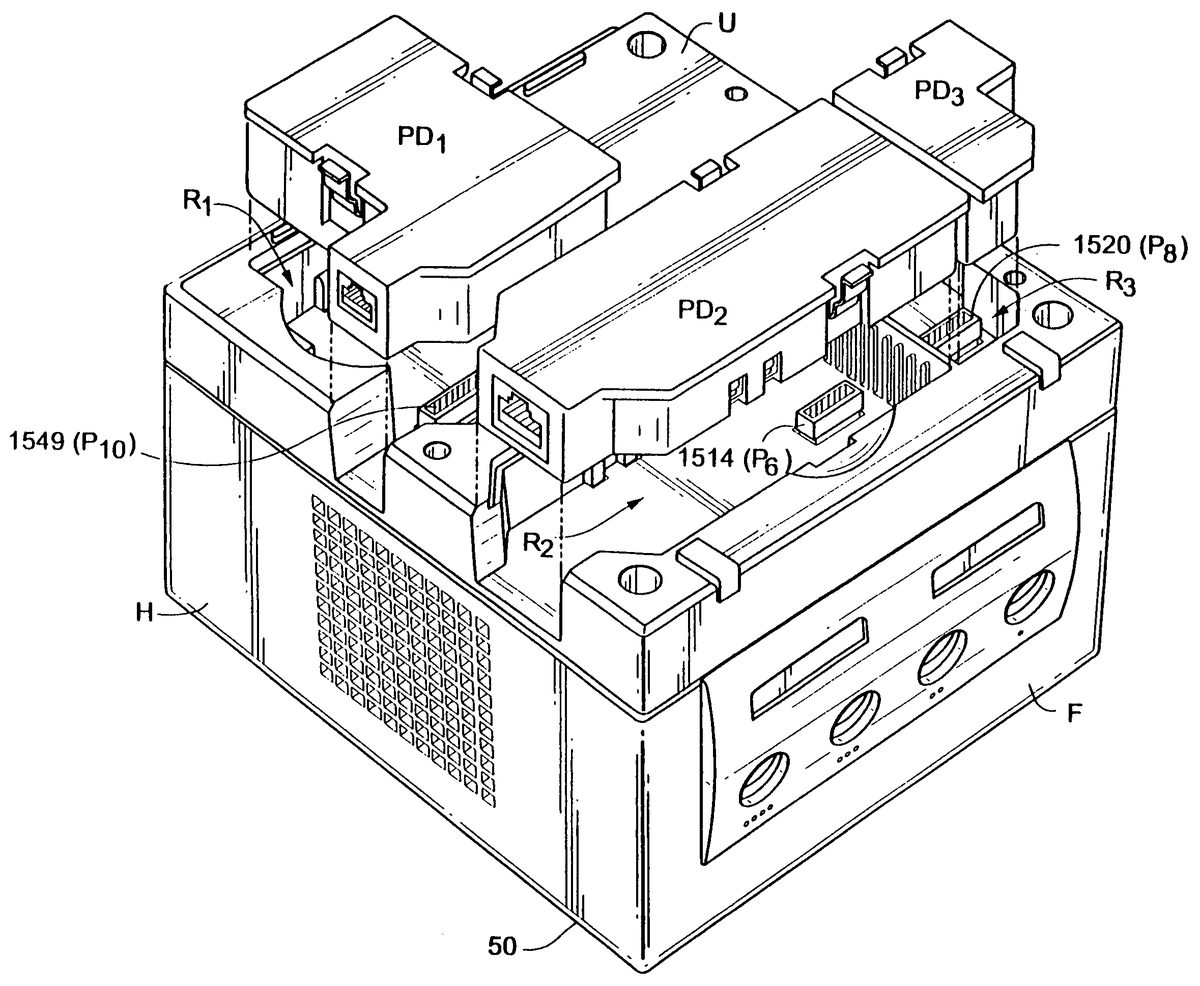
Referring toFIG. 12, the bottom surface U of housing H may include a number of recesses normally covered by covers (not shown). Removal of such covers exposes recesses and associated connectors. For example, a recess R1may include a “high speed port” connector such as the connector1549(P10) and a recess R2may expose and provide connection to a modem connector1514(P6). Further recess R3may expose and provide connection to an additional serial port such as the connector1520(P8). As best seen inFIG. 13, peripheral devices PD1, PD2and PD3can be mechanically configured to fit dimensionally within corresponding recess R1, R2, R3so that such peripheral devices can be mounted flush within the generally cubic configuration of housing H. In this way, the footprint of the video game system can remain the same, even if peripheral devices PD1, PD2and PD3are added. Such peripheral devices PD1, PD2, PD3may include a broadband adapter, a modem, or any other sort of electronic or electrical device providing data inputs and/or outputs. Devices PD1, PD2and PD3can be modular and inserted or removed into corresponding recess R at will to provide different expansion or other functionality for system50. Of course, a connecting cable or wireless communications device could be coupled to any of the connectors1514(P6),1520(P8) and1549(P10) to allow system50to be interconnected with a free-standing external system or device such as an external magnetic or optical disk drive. The example connectors of the video game system preferably (although not necessarily) provide power so that devices PD1, PD2and PD3need not provide their own power sources.
FIG. 13shows that the peripheral devices may include additional connectors for connections other than connections to the video game system. For example, if peripheral device PD2is a modem, it will include a connector for connecting the modem to connector1514(P6) and an additional connector for connecting the modem to a telephone line. The recesses R1, R2, R3are formed so that these additional connectors are easily accessible when the peripheral devices are inserted therein. In theFIG. 13example embodiment, each recess includes a cut-out portion (opening) formed through one of the sidewalls of housing H. The peripheral device is configured so that any additional connector thereof is accessible via this cut-out portion when the peripheral device is inserted into a recess.
As mentioned above, peripheral devices PD1, PD2and PD3may be any type of peripheral device for coupling to a home video game system. The particular elements making up a peripheral device will depend upon its functionality. Generally speaking, the peripheral device includes one or more electrical components and an electrical connector coupled to the electrical component(s) for connecting to one of the game system connectors. For example, a game controller typically includes user manipulable controls (such as buttons, joysticks, crosspads and the like) and an electrical connector that couples electrical signals based on inputs to the user manipulable controls to one of connectors1523. Of course, the game controller may include other components such as a memory for storing game data; processing circuitry such as a microprocessor, an application specific integrated circuit, a microcontroller, and the like; and a motor for vibrating the housing of the controller in accordance with commands received from the home video game system. Other peripheral devices may include communication circuits for communicating via wired or wireless communication networks; memory devices including optical, magnetic and semiconductor memories; display devices such as liquid crystal displays; printers; optical detectors such as digital cameras; computers; keypads; keyboards; pointing devices; voice recognition systems; etc.
Referring toFIGS. 9,10and14A–14B, additional slots S on front panel F provide access to connectors1516(P4) and1518(P5). Slots S may be used to insert portable memory devices such as flash memory for example. A “digicard” memory device M shown inFIG. 14Amay include 4 megabits (or 1 half megabit) of flash memory and fits snugly into slot S1underneath the controller port holes1523-0,1523-1mounted on front panel F. System50also supports SD-digicard adapter A shown inFIG. 14Bthat is compatible with stamp-sized, large capacity recording media, SD-memory cards C made by Matsushita. Such SD cards C may offer 64 megabits or more of non-volatile storage. The memory cards may be used to store game-related data. Other cartridge-based memory cards or other devices may also be received by slots S1, S2to interconnect system50with other types of internal or external peripheral or other devices.
Any of the various connectors described herein can be located in the various connector positions shown inFIGS. 8–14Bas desired and it will be appreciated that the invention is not limited in this respect.
While the invention has been described in connection with what is presently considered to be the most practical and preferred embodiment, it is to be understood that the invention is not to be limited to the disclosed embodiment, but on the contrary, is intended to cover various modifications and equivalent arrangements.
Claims
- A peripheral device for connection to a home video game system having a generally cube-shaped appearance and comprising an upper portion which receives a storage medium, at least one side portion to which input devices are connectable, and a bottom portion which contacts an underlying support surface, the bottom portion having a recess formed therein, the peripheral device comprising: an electrical component;a connector electrically coupled to the electrical component for connecting to a connector of the home video game system disposed in the recess;a housing containing the electrical component, wherein the housing is configured so that, when the peripheral device is inserted into the recess and the connector connects to the home video game system connector disposed in the recess, an outer surface of the housing is substantially flush with the bottom portion of the home video game system, whereby the generally cubed-shaped appearance of the home video game system remains substantially the same when the peripheral device is inserted into the recess.
- The peripheral device according to claim 1 , further comprising: an additional connector electrically coupled to the electrical component, the peripheral device being configured so that, when the peripheral device is inserted into the recess and the connector connects to the home video game system connector disposed in the recess, the additional electrical connector is externally accessible via a cut-out portion formed in a side portion of the home video game system.
- The peripheral device according to claim 1 , wherein the electrical component comprises communication circuitry.
- The peripheral device according to claim 3 , wherein the communication circuitry comprises a modem.
- The peripheral device according to claim 3 , wherein the communication circuitry comprises broadband communication circuitry.
- The peripheral device according to claim 3 , wherein the communication circuitry comprises wireless communication circuitry.
- The peripheral device according to claim 1 , wherein the electrical component comprises expansion memory.
- The peripheral device according to claim 1 , wherein the electrical component comprises a hard disk drive.
- The peripheral device according to claim 1 , wherein the connector is adapted for connection to a connector for a parallel interface of the home video game system.
- The peripheral device according to claim 1 , wherein the connector is adapted for connection to a connector for a serial interface of the home video game system.
Disclaimer: Data collected from the USPTO and may be malformed, incomplete, and/or otherwise inaccurate.