U.S. Pat. No. 7,001,272
VIDEO GAME DEVICE, VIDEO GAME METHOD, VIDEO GAME PROGRAM, AND VIDEO GAME SYSTEM
AssigneeKonami Corporation
Issue DateMarch 27, 2002
Illustrative Figure
Abstract
A game system that allows a player to manipulate a real interface device in a real space and have a representation of the real interface device (i.e., a virtual interface device) be displayed in a virtual space is disclosed. The position of the real interface device in the real space is detected by a position detector and converted into spatial coordinates by a three-dimensional input conversion means at predetermined time intervals. When a player moves the real interface device, a virtual interface device is displayed within the virtual space and moves identically with the real interface device. The virtual interface device is determined to have struck an object in the virtual space (e.g., an enemy) when the coordinates of at least a portion of the object in the virtual space are the same as, or within a predetermined range of, the coordinates of the virtual interface device.
Description
DETAILED DESCRIPTION OF THE PREFERRED EMBODIMENTS 1. Overview of the Invention In the present invention, the movement of a real interface device that a player controls within a real space R is displayed as the movement of a virtual interface device within a game space G. For example, in combat video games in which a player takes up a sword and battles with an enemy, the swinging and thrusting movements of the sword wielded by the player are converted into and displayed as the movements of a sword object within the game space G. As a further example, in a situation where a player plays a tennis game within the game space G, the movements of the racket wielded by the player are converted into and displayed as the movements of a racket wielded by an animated character that represents the player within the game space G. The present invention is also applicable to video games other than combat and sports games. For example, a game in which points are scored by having an animated character within the game space G jump to avoid obstacles is also made possible by the present invention. In order to convert the player's own movements into the movements of the animated character, the player may be asked to put on a hat, footwear, goggles, a belt, gloves, or other type of device, and the object(s) worn may serve as the real interface device(s). 2. First Embodiment A. Configuration of the Game System FIG. 1is a block diagram illustrating a game system1000according to a first embodiment of the present invention. The game system1000includes a control section1, an image processor2, an audio processor3, a semiconductor memory4, an operating section5, and a position detector6. The control section1includes a CPU10, ROM18and a RAM19. The CPU10conducts a number of ...
DETAILED DESCRIPTION OF THE PREFERRED EMBODIMENTS
1. Overview of the Invention
In the present invention, the movement of a real interface device that a player controls within a real space R is displayed as the movement of a virtual interface device within a game space G. For example, in combat video games in which a player takes up a sword and battles with an enemy, the swinging and thrusting movements of the sword wielded by the player are converted into and displayed as the movements of a sword object within the game space G. As a further example, in a situation where a player plays a tennis game within the game space G, the movements of the racket wielded by the player are converted into and displayed as the movements of a racket wielded by an animated character that represents the player within the game space G.
The present invention is also applicable to video games other than combat and sports games. For example, a game in which points are scored by having an animated character within the game space G jump to avoid obstacles is also made possible by the present invention. In order to convert the player's own movements into the movements of the animated character, the player may be asked to put on a hat, footwear, goggles, a belt, gloves, or other type of device, and the object(s) worn may serve as the real interface device(s).
2. First Embodiment
A. Configuration of the Game System
FIG. 1is a block diagram illustrating a game system1000according to a first embodiment of the present invention. The game system1000includes a control section1, an image processor2, an audio processor3, a semiconductor memory4, an operating section5, and a position detector6.
The control section1includes a CPU10, ROM18and a RAM19. The CPU10conducts a number of functions based on an operating system (OS) stored in the ROM18and on game data stored in the RAM19. These will be described in greater detail below. The OS stored in ROM18controls each portion of the game system1000, and the RAM19is used as a work area that temporarily saves various game data which is read out from the semiconductor memory4as needed.
The image processor2includes a GPU (graphics processing unit)21, a frame buffer22, and a monitor23. Based on calculations made by the CPU10, the GPU21writes CG images made up of polygon combinations into the frame buffer22, and are stored in the frame buffer22temporarily. The CG images stored in the frame buffer22are read out and displayed by the monitor23. Continuous processing and storing of CG images into the frame buffer22by the GPU21results in the display of an animated CG image on the monitor23.
The audio processor3includes an SPU (sound processing unit)31and a speaker32. The SPU31plays music and sound effects based upon music data and a variety of sound effects data.
Game programs are recorded in the semiconductor memory4.
The operating section5includes a real interface device51and controllers52. The real interface device51is an input means that a player manipulates within the real space R. The position detector6measures the position of the real interface device51in the real space R, and the measurement data therefrom is used to move a virtual interface device within the game space G such that the virtual interface device is a transposition of the real interface device51. In addition, the real interface device51may also be utilized both as an input means and an output means. For example, if the real interface device51is provided with a vibration means, and the virtual interface device collides with an object within the game space G, the vibration means in the real interface device51could be made to vibrate in response thereto. The controllers52are preset switches, buttons, joysticks, foot pedals, and other similar control members. The controllers52are input means for controlling objects and/or the virtual interface device within the game space G, and are manipulated by the player.
As noted above, the position detector6is a means for detecting the position of the real interface device51in the real space R. The position detector6employs, for example, light-emitting means installed in the real interface device51and a pair of sensors for sensing light emitted from the light-emitting means. The position detector6further includes a measurement unit that determines the position of the real interface device51in the real space R, based upon the light emitted from the light-emitting means, and sends this position data to the control section1. The position data sent to the control section1is, for example, expressed in three-dimensional coordinates in the real space R, numbers representing sub-spaces subdivided from within the real space, or another type of coordinate system known to one of ordinary skill in the art.
Instead of the aforementioned light-emitting means, it is also possible to utilize ultrasound signal-emitting means installed in the real interface device51, together with a pair of sensors that receive sound from the ultrasound signal-emitting means.
B. An Example of A Game System
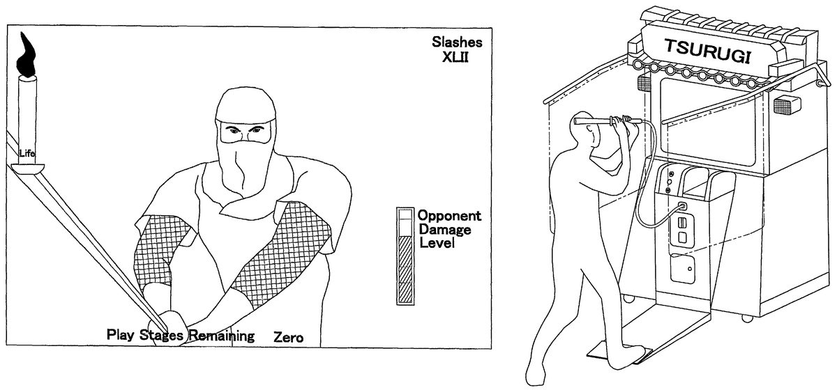
FIG. 2is an oblique view of the outward appearance of a combat video game system2000in which the foregoing game system1000is employed, and illustrates one example in which the present invention is applied to a combat video game. The combat video game system2000includes a game device100, and a sword type of interface device200(hereinafter referred to as “sword200”) that serves as one example of a real interface device51. The sword200is connected to the game device100by an RS232C connection or other similar type of connector. A cable supplying power from the game device100is also connected to the sword200. Note, however, that it would be readily apparent to one of ordinary skill in the art that the sword200could be powered by an independent power source (such as a battery pack), and that the sword200could be configured to be connected to the game device100via any one of a number of wireless connections available on the market.
A monitor101for image output is provided on the upper front upper portion of the game device100console. CCD cameras102aand102b, which are only one example of sensors included in the position detector6, are installed on the left and right uppermost portions of the console. The CCD cameras102aand102bdetect light from the light-emitting means installed in a predetermined location on the sword200. Although not shown in the figure, a position measurement means is connected to the CCD cameras102aand102b, and specifies the light-emitting positions in the real space R based on the light detected by the CCD cameras102aand102b. A pair of bars103project out of the left and right sides of the rear upper portion of the console and extend forward therefrom, and protective curtains104are installed on the bars103. The protective curtains104serve to protect the area surrounding the game device100when a player is brandishing the sword200in the play space. Speakers105(which are examples of the speaker32depicted inFIG. 1) are installed on both the left and right sides of the upper portion of the monitor101, and serve to output game background music and sound effects to the player. Switches106are provided in the middle of the lower portion of the console, and allow the player to select menus that are displayed on the monitor101. The switches106are one specific example of the controllers52described above. A foot pedal107is provided at floor level on the front of the console. By stepping on the foot pedal10, a player is able to manipulate a sword object that represents the sword200in the game space G. The foot pedal107is another specific example of the controllers52described above. A coin deposit slot108is provided in the middle of the lower portion of the console, and serves to accept coins inserted by the player in order to pay for the game.
B-1. The Game Device
FIG. 3is a lateral view of the game device100shown inFIG. 2. As this figure shows, the bars103are rotatably installed on fulcrums110in the rear of upper part of the console, and project forward horizontally from the fulcrums110. Gas springs109are fitted to the bars103, and through the extension/compression thereof, the bars103are rotatable around the fulcrums110within a fixed range in the direction of the arrow in the figure. Even on the rare instance that someone was to dangle from the protective curtains104, the protective curtains104are prevented from coming off the bars103because the bars103are rotatably installed on the console.
B-2. The Sword
FIG. 4shows the detailed structure of the sword200. The sword200includes a grip201and a blade202. The blade202is composed of a clear plastic. Two light-emitting means203aand203bare installed in the interior of the blade202at two predetermined points Q1and Q2that are in different positions along the axial direction. Light from the light-emitting means203aand203bis detected by the CCD cameras102aand102brespectively. The light-emitting means203aand203bare not particularly limited, but may for example include LEDs that emit infrared light. Because of the directionality in the orientation of the light emitted from LEDs, the light-emitting means is preferably composed of a plurality of LEDs.
A vibrating means204for vibrating the sword is provided in the interior of the grip portion201. The vibrating means204may be composed of an eccentric cam and a motor for rotating the eccentric cam. As will be described later in greater detail, when the sword object in the game space G is determined to have struck an enemy or another object, the motor will be driven to rotate the eccentric cam, which in turn vibrates the sword200. By adjusting the interval of the motor drive pulse, the rotational speed of the eccentric cam may be controlled to strengthen and/or weaken the vibration. Further, switches205aand205bare provided on the grip portion201. The switches205aand205bare utilized to select from menus that appear on the monitor101. In addition, a cable206that transmits electric current to drive the aforementioned motor, and a cord for hanging the sword200on the main unit, are both provided in the grip portion201.
C. Overview Of The Combat Game
Next, an overview of a combat video game played on the combat video game system2000will be explained usingFIGS. 1 and 5through18.FIG. 5is a scene from the combat video game, andFIG. 6shows a player playing the combat video game. In this video game, enemies holding weapons such as swords appear in succession and assail the player. Utilizing the sword200connected with the game device100, the player, as shown inFIG. 6, swings and thrusts the sword200in order to control the sword object within the game space G. As noted above, the sword object is a transposition of the sword200within the game space G. The player's score and a candle that signifies the amount of life remaining in the player are displayed in the upper left portion of the screen. The amount of life left for the enemy is displayed in the lower right portion of the screen.
Prior to beginning the game, the player may select the level of difficulty, and may also select a weapon, e.g., a knife, a spear, or a bow and arrows, in accordance with the level of difficulty. The player advances and turns from one direction to another within the game space G by controlling the game system. Furthermore, by stepping on the foot pedal107, the player may move ahead a fixed distance in a predetermined direction within the game space G. When the player inflicts a predetermined amount of damage on the enemy by knocking down foes encountered while moving within in game space G, the selected level of difficulty ends, and the player may then choose to move onto a higher level of difficulty. The game ends once the player's remaining life is gone.
C-1. Coordinate Conversion
FIGS. 7 and 8show the coordinate conversion concept that forms the foundation of the present combat video game. Three spatial coordinate systems are assumed in the present video game system. The first is a sensor coordinate system that utilizes the CCD cameras102aand102bas references to establish the position of the sword200within the real space R with three-dimensional coordinates. The second is a player coordinate system that utilizes the player as a reference to establish the position of the sword200within the real space R in three dimensional coordinates. The third is a game space coordinate system that establishes the position of the sword200within the game space G in three dimensional coordinates.
C-1—1. Conversion From A Sensor Coordinate System Used In The Real
Space R To A Player Coordinate System
FIG. 7shows the relationship between the sensor coordinate system and the player coordinate system. A cuboid whose boundaries are detectable with the CCD cameras102aand102bis assumed as the real space R. The cuboid assumed as the real space R in the present example hovers 50 cm from the floor surface on which the game device100is placed, and extends up to the CCD cameras102aand102bdisposed on the front of the game device100. The height of the cuboid is 200 cm, the depth is 200 cm, and the width is 150 cm. The size of the cuboid is set to be within the sensing capability of the CCD cameras102aand102b, and to be large enough to accommodate a player's movements.
The sensor coordinate system will be explained first. The sensor coordinate system is a system of coordinates in which a vertex So corresponding to CCD camera102ais the origin, an imaginary line that extends from the CCD camera102ato the CCD camera102bis the x-axis, an imaginary line that extends down from the CCD camera102ais the y-axis, and an imaginary line that extends out from the front of the game device is the z-axis. Each edge of the cuboid representing the real space R in the sensor coordinate system is divided into 256 spaces, whose coordinates are expressed as values from 0 to 255. For example, the coordinates of the vertex S1, which corresponds to CDD camera102b, will be (255, 0, 0) in this system.
Next, the player coordinate system will be explained. In this example, the origin P0in the player coordinate system is a position on the foot pedal107further toward the front of the game device than the CCD cameras102aand102b. Assume for example that the foot pedal107, at the front of the game device100, is on the floor surface 60 cm further to the front of the game device than CCD cameras102aand102b. Then, an x-axis and a z-axis extend in the same respective directions as the x-axis and z-axis in the foregoing sensor coordinate system, while a y-axis extends upward in a direction opposite that of the y-axis. Each coordinate axis is scaled with 1 cm increments. In this player coordinate system, the coordinates of a point P3where the y-axis intersects with the lower plane of the real space R will be (0, 50, 0). Likewise, the coordinates of a point P2where the y-axis intersects with the upper plane of the real space R will be (0, 250, 0).
As an example in which sensor coordinates are converted into player coordinates, consider the origin S0in the sensor coordinate system. The sensor coordinate system origin S0(0, 0, 0) will be expressed as (−75, 250, −60) in the player coordinate system.
C-1-2. Conversion From The Player Coordinate System To The Game Space Coordinate System
FIG. 8shows the relationship between the player coordinate system and the game space coordinate system. The game space G is a virtual space in which the video game is played, such as a virtual building, a virtual forest, or other area, and is a predetermined size that is set by the video game supplier. A hypothetical game space G might be a cuboid 2000 m wide, 2000 m deep and 200 m high, for example. Taking the origin G0(0, 0, 0) to be in the middle of one of the lower edges of the cuboid, an x-axis extends along the lower edge of the cuboid in which the origin G0is placed, a z-axis extends perpendicular to the x-axis and along the bottom of the cuboid, and a y-axis extends upward perpendicular to the x-axis and the z-axis. Each coordinate axis is scaled with 1 m increments.
The relationship between the player coordinate system and the game space coordinate system is that the y-axis and the y-axis extend in the same direction, while the x-axis and the x-axis, and the z-axis and the z-axis, both extend in a parallel, but opposite, direction with respect to each another.
The origin G0in the game space coordinate system and the origin P0in the player coordinate system are the same when the game starts. Thereafter, when the player moves forward to press on the foot pedal107, or when the player advances or turns, the origins in the game space coordinate system and the player coordinate system gradually diverge. When the two origins are equal, the coordinates (−75, 250, −60) in the player coordinate system, which is the origin S0in the sensor coordinate system, will be (75, 250, 60) in the game space coordinate system. It should be noted that the conversions described above for the coordinate systems are no more than a single example, and the coordinate system conversions can be generally performed utilizing a known method as an affine transformation.
In the present combat video game system2000, the positions of the two points Q1, Q2on the sword200in the real space R are specified in the sensor coordinate system, and these coordinates are subsequently converted into the player coordinate system and further into the game space coordinate system. The display position of the sword object on the monitor101is determined by making a perspective-projection transformation of the coordinates in the game space coordinate system, and the sword object is then displayed. This coordinate conversion allows a player to play a game without sensing incongruity between real space and the game space, by allowing him to move his body rather than just manipulating an object in the game space.
C-2. Processes Performed By The CPU
Referring again toFIG. 1, the process which the CPU10performs will now be explained. The CPU10includes correction means11, difficulty level selection means12, three dimensional input conversion means13, hit determination means14, audio output control means15, maneuver determination means16, and status determination means17.
The correction means11performs a process that corrects for differences in player height. For example, the standard height of a player is assumed to be 170 cm. When the player is a child who is shorter than 170 cm, the correction means11performs a correction process to prevent the sword object from being awkwardly displayed only at the bottom of the screen.
Specifically, prior to the start of the game the correction means11prompts the player into a basic stance.FIG. 9is an example of a screen that the correction means11displays in order to prompt the player into this stance. The correction means11deduces the player's height based upon the position of the sword200when in this stance, and determines a correction coefficient. For example, the correction means11assumes 120 cm to be the standard height of the sword200when the player is in the basic stance. If the height of the sword200detected from a player in the basic stance is 60 cm, i.e., half the standard height, the correction means11determines the correction coefficient to be “2.” From then on, the correction means11multiplies the detected height of the sword200by the correction coefficient 2, enabling the same display effects to be produced as with that of a standard player, even for small children. In fact, depending on the height of the player, it is also possible to use the different movements of the sword200to determine the correction coefficient. Specifically, the movement of the sword200is expressed by the change in the combination of its previous positions and the direction in which it is traveling. Thus, for example, a method can be provided that computes the correction coefficient from distributions in the range of travel of the sword200.
After, or prior to, the determination of the correction coefficient by the correction means11, the level of difficulty of the game can be selected with the difficulty level selection means12. The selection of a weapon in accordance with the level of difficulty can also occur while selecting the level of difficulty, or it can occur after the level of difficulty has been selected. The difficulty level selection means12utilizes the switch106installed in the game device100, and the switch205on the sword200, in order to accept the difficulty level selection from the player. In addition, when a player points the sword200at a menu on the monitor101that he or she has selected, the difficulty level selection means12displays a marker where a line that extends from the straight line joining the light-emitting means203aand203bintersects the monitor101. The difficulty level selection means12will then select the menu in which the marker is placed when the player presses the switch205.FIG. 10is an example of a difficulty level selection screen that the difficulty level selection means12displays. A marker indicating where the sword200is aimed is displayed on the menu item titled “Beginner Mode.”
The three dimensional input conversion means13carries out a coordinate transformation process that converts the sensor coordinates of the light-emitting means203aand203bin the sword200into player coordinates, and then into game space coordinates. Display of the sword object is carried out by computing its display position on the monitor101based on the game space coordinates calculated. The three dimensional input conversion means13performs the coordinate transformation process at predetermined time intervals, e.g. every 16 msec. Accordingly, the movement of the sword200controlled by a player is thereby expressed as the movement of a sword object displayed on the monitor101. This enables a player to play the video game the feeling that they themselves are acting in it, rather than just feeling that they are controlling a sword object in the game.
If for example a player has swung the sword200as shown inFIG. 11B, the same movement of the sword object will displayed on the screen, as illustrated inFIG. 11A. Moreover, as shown in the sameFIG. 11A, the trajectory of the sword object will also displayed. Likewise, as shown inFIGS. 12A and 12B, when an enemy appears and makes an attack on the player, if the player acts to stop the enemy's sword using the sword200, the sword object in the display will move in the same manner.
The hit determining means14determines whether or not the sword object has struck an enemy or another object such as a rock or other object within the game space G. In the present game system, because the movements of the sword object controlled by the player are arbitrary and thus cannot be predicted by the system, the hit determining means14stores the sword object's trajectory over a predetermined time period t in order to determine whether or not the sword object has struck another object and what that object is.
FIG. 13is a trajectory table in which the coordinates of two game space points q1, q2on the sword object are stored in a time series. The two game space points q1and q2correspond to the two points Q1and Q2on the sword200. The three dimensional input conversion means13converts the coordinates of the two points Q1and Q2on the sword200that are taken every 16 msec, into game space coordinates q1, q2for the sword object. The trajectory table then stores the coordinates of the two game space points q1, q2taken over the previous 256 msec in the RAM19.
Based on the coordinates of the two game space points q1, q2for the sword object, the hit determining means14can establish a straight line that represents the blade of the sword object. In addition, assuming the point q1is at the base of the blade, and the point q2is near the tip of the blade, the tip of the blade can also be established with a point q3. The point q3of the blade is a point in line with points q1and q2, and a fixed distance d further along the blade from point q2. Utilizing the trajectory table, the hit determining means14will calculate a plane that expresses the linear trajectory of the blade. The hit determining means14determines whether or not the sword object has struck anything by determining whether or not an enemy's sword, an enemy's body, or another object is within the plane calculated.
In addition, the hit determining means14determines the speed of the sword object by measuring the distances that points q1and q2have traveled every 16 msec. In accordance with the speed of the sword object, the hit determining means14will determine how deep it has entered an object. Furthermore, the hit determining means14will also determine the degree to which the sword object has struck another object. For example, the hit determining means14will rate the hit as “cut clothing only”, “body cut”, “slashed to the bone” or will determine that the attack has missed altogether.
Note that when the sword200moves very quickly, there will be times when the stored sword object coordinates will not overlap with another object. It may happen that, for example, the sword object at time T1is on the left side of an enemy, and at time T2is on the right side of the enemy. In this sort of situation as well, the hit determining means14will determine that a hit has been made from the trajectory of the sword object blade.
In accordance with the results of the hit determination, the audio output control means15will output sound effect data to the speaker32that was read out from the semiconductor memory4to the RAM19. The sound effects can include, but are not limited to, the sound of the sword striking another sword, the sound of the sword ripping an enemy's clothes, and the sound of the sword swishing as it misses. Because the sound effects vary with the results of the hit determination, the realism of the game is improved.
The maneuver determining means16determines whether or not a prescribed command has been input based on the trajectory of the sword object. The prescribed commands are input according to predetermined trajectory patterns of the sword object and attacks on the enemies. The prescribed commands and the predetermined trajectory patterns are stored in the RAM19(and are not illustrated in the figures). For example, based on the foregoing trajectory table, the maneuver determining means16determines whether or not a player has input a cross pattern, i.e., one that is intended to kill the opponent. If this pattern has been input, an attack corresponding to the cross pattern is executed. Thus, the player can have an even greater feeling that he himself is participating in the game.
The maneuver determining means16also determines whether or not the foot pedal107has been pressed. If it has been pressed, the position of the origin P0in the player coordinate system is advanced in the game space G by the number of times pressed. The distance that the player moves forward in the game space G each time the foot pedal107is pressed is set beforehand to be, for example, 1 m. In response to the player's advance, the maneuver determining means16also shifts the game space coordinates for the sword object.FIGS. 14A and 14Bare screen shots showing the changes in the display when the foot pedal107has been pressed.FIG. 14Ais a screen shot illustrating a situation in which the sword object will not strike the opponent because the player is too far away from him.FIG. 14Bis a screen shot illustrating what occurs when the player presses on the foot pedal17(as shown inFIG. 14C) and swings the sword object. As illustrated in the figure, the player moves closer to the opponent in the game space G (i.e., the image is zoomed up), thereby allowing the player's sword object to strike the opponent. By depressing the foot pedal107, and at the same time using his or her entire body to attack the opponent, the player can feel a sense of presence in the game.
In addition to these processes, the maneuver determining means16also determines whether or not the player has used a predetermined weapon—e.g., a knife which can be thrown. For instance, with the sword200pointed at an opponent on the screen, a knife can be thrown at the targeted opponent if the switches205aand205bare pressed to order that the knife be thrown. When the line extending through the two points Q1, Q2on the sword200intersects an opponent on the screen, a marker indicating that the player has targeted that opponent is preferably displayed.
In accordance with the hit determination results and the maneuver determination results, the status determining means17calculates the amount of damage on the opponent and the remaining life in the player. For example, when the hit determination results are that only an opponent's clothing has been ripped, the opponent damage level will be “0.” When the opponent has only been grazed or knocked down, the opponent damage level will be increased a fixed amount. The degree of damage to the opponent, and degree to which the opponent damage level has been increased, are both stored in the RAM19(not shown in the figures).
When the results of the maneuver determination are that a prescribed command has been input or that a weapon has been used, the status determination means17increases the opponent damage level to the degree corresponding to the prescribed command or weapon used. The prescribed commands and the weapons, as well as the degree of increase in the opponent damage level, are stored in the RAM19(not shown in the figures).
Meanwhile, the status determining means17updates the amount of life remaining in the player in accordance with the position of the opponent, the position of the player, and the movement of the player, in the game space G. In situation in which the player was not able to prevent an enemy attack, the amount of life that the player has remaining will be decreased by a predetermined amount per round of enemy attack.FIG. 15is a screen shot in which the status determining means17lowers the amount of life remaining in a player who has undergone an enemy attack.
Furthermore, the status determining means17will vibrate the sword200in response to a hit by activating the motor204disposed in the handle201of the sword200. The video game is made more realistic because will not only see that he has struck something, but also physically feel it due to the vibration. Moreover, the game will feel more realistic because the strength of the vibration provided can be varied according to the strength of the hit.
C-3. Process Flow
FIGS. 16 through 19are flowcharts illustrating the flow of the overall processes/procedures in the present combat video game system2000. Below, details on the flow of the processes in the present game system will be explained with reference to these figures.
C-3-1. Main Routine
FIG. 16is a flowchart illustrating the flow of the main routine of the present video game system. This routine is begun by a player inserting a coin into the coin deposit slot108in the game device100.
Step S1: The correction means11carries out the correction process noted above, and calculates a correction coefficient in order to correct for the player's height. This process will be described below when discussingFIG. 17.
Step S2: The difficulty level selection means12accepts the selection of a difficulty level by a player, such as beginner, intermediate, or advanced. This process will be described below when discussingFIG. 18. It should be noted that the difficulty level selection process may be performed prior to the correction process noted above.
Step S3: Data is loaded after the correction process and the difficulty level selection process. In other words, the game program and data required during the course of the game are read into the RAM19from the semiconductor memory4. When the data is loaded, a game screen such as the one shown inFIG. 11is displayed and the game begins.
Step S4: After the game has begun, the processes in steps S5through S18are carried out at predetermined time intervals. In the present example, that time interval is set at 16 msec.
Step S5: The three dimensional input conversion means13acquires the sensor coordinates of the sword200in the real space R from the position detector6every 16 msec.
Step S6: Next, the three dimensional input conversion means13converts the acquired sensor coordinates into player coordinates, and then into game space coordinates. This process will be described in greater detail below. The game space coordinates are then written into the trajectory table in the RAM19by the hit determining means14.
Step S7: The game space coordinates are then transformed into a perspective projection by the three dimensional input conversion means13in order to calculate the display position of the sword object on the monitor101. The sword object is accordingly displayed on the monitor101. In other words, the sword object will be displayed every 16 msec during the course of the game.
Steps S8, S9, S10: The hit determining means14determines the trajectory of the sword during the past 256 msec from the trajectory table, and at Step S8determines whether or not the sword object has struck an enemy or an object other than an enemy. If there has been a hit on the enemy, the level of damage to the enemy is calculated at Step S9by the status determining means17. If, however, the object struck is something other than the enemy, the opponent damage level will not change. In addition, the sword200will be vibrated at Step S10in accordance with the object and the force with which it was struck, i.e., the status determining means17will vary the drive pulse intervals for the motor204built into the sword200. For example, the reality of the game may be heightened by imparting a strong vibration to the sword200when the enemy has been knocked down and only a weak vibration when the enemy is grazed.
Step S11: The audio output control means15outputs sound effects in accordance with the hit determination results.
Steps S12, S13: At Step S12, the maneuver determining means16determines whether or not a prescribed command has been input. In other words, the maneuver determining means16determines the trajectory of the sword object within the game space G based on the data in the trajectory table, and determines whether or not the trajectory corresponds to a predetermined pattern. Discrepancies in the predetermined pattern are tolerated to a certain extent in making this determination. If the trajectory corresponds a prescribed command, then at Step S13the status determining means17raises the opponent damage level to the degree that is associated with the prescribed command, and updates the display. If a prescribed command has not been input, then nothing is done.
Steps S14, S15, S16: At Step S14, the maneuver determining means16determines whether or not the player is pointing the sword200at an enemy on the monitor101, and if so, displays a marker thereon. The marker may, for example, be a circle encompassing the targeted enemy. At Step S15, it is determined whether or not a weapon has been discharged toward the targeted enemy (e.g., a knife is thrown at the enemy). At Step S16, if a weapon has been discharged toward the targeted enemy, the status determining means17will increases the level of opponent damage by an amount associated with that type of weapon, and then update the display.
Step S17: Depending on whether or not the player's sword object has warded off an attack from the enemy, the status determining means17calculates the amount of player life remaining and updates the display. For example, if it is determined that an enemy's sword object and the player's sword object have struck, the hit determining means may determine that the enemy's attack was fended off. Conversely, if an enemy has attacked the player and the player's sword object has not struck the enemy's sword object, it may be determined that the player has been injured.
Step S18: In this step, it is determined whether or not the player has any life remaining. If the player does not have any life remaining, then the process moves to Step S19. If the player does have life remaining, the routine returns to Step S4, and the S4–S18process is repeated every 16 msec.
Steps S19, S20, S21, S22: At Step S20, it is determined whether or not the selected stage has been cleared, and if it has not been cleared, “Game Over” is displayed and the game is terminated. If it has been cleared, the player's results are displayed at Step S21, and then at Step S22a screen asking the player whether or not he or she wants to continue will be displayed. If “Continue” is selected, the routine returns once more to Step S2, and that process is again carried out. If “End” is selected, the game terminates.
C-3-2. Correction Routine
FIG. 17shows the correction process carried out in Step S1of the main routine. At Step S101, the correction means11displays the screen shown inFIG. 9, which prompts the player to assume the basic stance. At Step S102, the correction means11stands by for a fixed period of time, and then detects the sensor coordinates of the two points Q1, Q2on the sword200. The player's height is then estimated from the sensor coordinates read, and the correction coefficient is determined.
C-3—3. Difficulty Level Selection Routine
FIG. 18shows the difficulty level selection process conducted in Step S2. This flowchart explains what occurs when the sword200is used to make a menu selection.
Steps S201, S202, S203: At Step S201, the difficulty level selection means12reads in the sensor coordinates for the two points Q1, Q2on the sword200. At Step S202, the difficulty level selection means12calculates the point in real space where the imaginary line extending from the tip of the sword200intersects the monitor101. At Step203, the difficulty level selection means12then calculates the screen coordinates in which the imaginary line intersects with the monitor101.
Steps S204, S205, S206: At Step S204, the difficulty level selection means12will display a marker on the point on the monitor101that was determined in Step S203. At Step S205, when either of the switches205aor205bon the sword200is pressed with the marker placed on a menu option on the monitor101, the difficulty level selection means12will select the level of difficulty indicated.
As described earlier, the selection of the level of difficulty and weapon to be used may be accomplished through a switch on the game device main unit, or through a switch on the sword200.
C-3-4. Coordinate Conversion Routine
FIG. 19shows the coordinate conversion process conducted in Step S6of the main routine.
At Step S601, the three dimensional input conversion means13uses the correction coefficient determined in Step S1and corrects the two sensor coordinates of the sword200in the real space R. Accordingly, the actions of all players are made equivalent to the actions of a standard player, regardless of differences in height.
At Step S602, the three dimensional input conversion means13converts the values of the corrected sensor coordinates into player coordinates in the player coordinate system, and then at Step S603converts the player coordinates into game space coordinates in the game space coordinate system. At Step S604, it performs a perspective projection transformation on the game space coordinates of the sword200in order to calculate the position in which the sword object will be displayed on the monitor101.
3. Other Embodiments
A. Another Example of Converting A Position In The Real Space Into A Position In The Game Space
Depending on the type of video game and on the type of virtual interface device employed, a position in the real space R and a position in the game space G may be specified with something other than three dimensional coordinates. For example, the real space R and the game space G can be respectively partitioned into a number of real cells r1, r2, . . . and virtual cells g1, g2, . . . of predetermined size, and a cell storage member can be provided that stores both the cell numbers identifying each cell, and the position of each cell.
In this modification, the three dimensional input conversion means13will convert the three dimensional coordinates position detector6into real cell numbers, convert the real cell numbers into virtual cell numbers, and then determine the display position of the sword object based on the virtual cell numbers.
B. Another Example of How The Origin In The Player Coordinate System Is Chosen
It is also possible to make the both origin in the player coordinate system and the size of the increments on the coordinate axes different, depending upon the height of the player. This allows the game to be adjusted for the height of the player. For example, the correction means11will store a player coordinate system in which one particular height is considered to be the standard.
If a player is determined to be taller than this standard height by the correction means at Step S1, the position of the origin in the player coordinate system will be lowered beneath the standard position, and the size of the increments on the coordinate axes will be made larger. If the player is determined to be shorter than the standard height, the opposite process will be carried out.
C. Another Example of Hit Determination
FIGS. 20A,20B, and20C illustrate a method of speeding up the ability of the hit determining means14to determine whether or not the sword object has struck a target object. The solid lines shown inFIG. 20Aindicate the position of the blade of the sword object in the game space G at a time T1and a time T2, with time T2being 16 msec after T1.FIG. 20Bshows the blade of the sword object represented by N number of points at time T1and time T2.FIG. 20Cshows the trajectory of the sword object between times T1and T2as represented by the N number points on the blade thereof.
In order to determine whether or not the sword object has struck something between times T1and T2, the hit determining means14will calculate the distances between each point on the sword object and the target object. If the distance between one or more of the points is determined to be at or below a predetermined value, then it is determined that the target object has been struck by the sword object. This method speeds up the ability of the hit determining means14to determine whether or not the sword object has struck a target object, because it does not require one or more points on the sword object to actually overlap a target object in order for a hit determination to be made. Instead, the target object need only be within a predetermined distance of one or more of a reduced number of points on the sword object. This allows the computational load placed on the CPU10to be reduced, and thus allows the hit determination to be made more quickly.
D. Another Example Of Determining Whether Or Not A Prescribed Command Has Been Entered
The maneuver determining means16may determine whether or not a prescribed command has been input in a manner different from that described above.FIG. 21is a diagram of a real space R partitioned into a suitable number of sub-spaces (hereinafter referred to as “cells”). In the same way as described above, the real space R is partitioned into a number of real cells r1, r2, . . . and cell numbers for identifying the cells are ascribed to each real cell. The maneuver determining means16stores the cell numbers in the sequence in which the two points Q1and Q2on the sword200have passed through the cells within a predetermined time period Δ t3. From the stored cell numbers, the maneuver determining means16then compares the pattern of passage through the real cells with a prescribed pattern to determine whether or not a prescribed command has been input.
E. Modifications To The Real Interface device
Vibration may be provided in two or more places on the real interface device. For example, a vibration means can be place at both ends of the sword200, which allows the strength of the vibration applied to the sword200to be varied according to the object struck by the sword object in the game space. For example, both vibrating means could be activated when the player's sword object strikes an enemy's sword object, while only one vibrating means could be activated when the player's sword object strikes a softer object.
Moreover, output means other than the vibration means may be installed on the real interface device. For example, an audio output means, a light output means, or the like could be installed on the real interface device in accordance with the nature of the video game.
F. Programs and Recording Media
Software programs that execute the aforementioned game method on a computer are included in the scope of the present invention, as too are computer-readable recording media on which the programs are recorded. Computer-readable recording media include, but are not limited to, floppy disks, hard disks, semiconductor memory, CD-ROMs, DVDs, magneto-optical disks (MOs) and other computer-read/writeable recording media that would allow the aforementioned software programs to be stored thereon.
This application claims priority to Japanese Patent Application No. 2001-096856. The entire disclosure of Japanese Patent Application No. 2001-096856 is hereby incorporated herein by reference.
While only selected embodiments have been chosen to illustrate the present invention, it will be apparent to those skilled in the art from this disclosure that various changes and modifications can be made herein without departing from the scope of the invention as defined in the appended claims. Furthermore, the foregoing description of the embodiments according to the present invention are provided for illustration only, and not for the purpose of limiting the invention as defined by the appended claims and their equivalents.
Claims
- A video game device in which a real interface device that a player within a real space manipulates is represented by a virtual interface device within a virtual space, the video game device comprising: position detecting means that detects the three dimensional coordinates of at least two points on the real interface device within the real space;conversion means that converts the three dimensional coordinates of the real interface device within the real space into three dimensional coordinates within the virtual space, and displays the virtual interface device in the three dimensional coordinates within the virtual space on a display;operating means that displays movements of the virtual interface device on the display, the operating means causing the position detecting means to detect the three dimensional coordinates of the real interface device within the real space and the conversion means to determine the three dimensional coordinates of the virtual interface device within the virtual space at predetermined time intervals;intersection display control means that calculates a point in which an imaginary straight line that extends between the points on the real interface device intersects with the display and displays a marker thereon;and selection accepting means that determines whether or not the point lies on an object being displayed on the display, and allows the player to select the object if the point lies thereon.
- The video game device set forth in claim 1 , further comprising: trajectory storing means that stores the three dimensional coordinates of the virtual interface device taken at predetermined time intervals;and hit determining means that calculates a trajectory and speed of the virtual interface device based upon the three dimensional coordinates stored in the trajectory storing means, determines whether or not the virtual interface device has struck an object within the virtual space based on the trajectory and speed thereof, and specifics the object struck if a strike has occurred.
- The video game device set forth in claim 1 , comprising: correction means that detects any difference between the player's height and a predetermined standard height based upon the three dimensional coordinates of the real interface device, and corrects the three dimensional coordinates of the virtual interface device if any difference exists.
- The video game device set forth in claim 1 , wherein the position detecting means further comprises: light emitting means provided on the real interface device;at least a pair of light detecting means that detect light from the light emitting means;and measuring means that measures the position of the light emitting means based on the light detected therefrom, and outputs the position of the light emitting means to the conversion means.
- A video game device in which a real interface device that a player within a real space manipulates is represented by a virtual interface device within a virtual space, the video game device comprising: position detecting means that detects three dimensional coordinates of the real interface device within the real space;conversion means that converts the three dimensional coordinates of the real interface device within the real space into three dimensional coordinates within the virtual space, and displays the virtual interface device in the three dimensional coordinates within the virtual space on a display;and operating means that displays movements of the virtual interface device on the display, the operating means causing the position detecting means to detect the three dimensional coordinates of the real interface device within the real space and the conversion means to determine the three dimensional coordinates of the virtual interface device within the virtual space at predetermined time intervals;trajectory storing means that stores the three dimensional coordinates of the virtual interface device taken at predetermined time intervals;command storage means that stores a plurality of commands that are associated on a one-to-one basis with a plurality of predetermined trajectory patterns of the virtual interface device;and command execution means that calculates a trajectory of the virtual interface device based upon the three dimensional coordinates of the virtual interface device stored in the trajectory storing means, determines whether or not the trajectory matches any of the predetermined trajectory patterns, and executes the command associated with the predetermined trajectory pattern if a match exists.
- The video game device set forth in claim 5 , further comprising: hit determining means that calculates a trajectory and speed of the virtual interface device based upon the three dimensional coordinates stored in the trajectory storing means, determines whether or not the virtual interface device has struck an object within the virtual space based on the trajectory and speed thereof, and specifies the object struck if a strike has occurred.
- The video game device set forth in claim 5 , comprising: correction means that detects any difference between the player's height and a predetermined standard height based upon the three dimensional coordinates of the real interface device, and corrects the three dimensional coordinates of the virtual interface device if any difference exists.
- The video game device set forth in claim 5 , wherein the position detecting means further comprises: light emitting means provided on the real interface device;at least a pair of light detecting means that detect light from the light emitting means;and measuring means that measures the position of the light emitting means based on the light detected therefrom, and outputs the position of the light emitting means to the conversion means.
- A video game device in which a real interface device that a player within a real space manipulates is represented by a virtual interface device within a virtual space, the video game device comprising: position detecting means that detects three dimensional coordinates of the real interface device within the real space;conversion means tat converts the three dimensional coordinates of the real interface device within the real space into three dimensional coordinates within the virtual space, and displays the virtual interface device in the three dimensional coordinates within the virtual space on a display;and operating means that displays movements of the virtual interface device on the display, the operating means causing the position detecting means to detect the three dimensional coordinates of the real interface device within the real space and the conversion means to determine the three dimensional coordinates of the virtual interface device within the virtual space at predetermined time intervals;trajectory storing means that stores the three dimensional coordinates of the real interface device taken at predetermined time intervals;command storage means that stores a plurality of commands that are associated on a one-to-one basis with a plurality of predetermined trajectory patterns of the real interface device;and command execution means that calculates a trajectory of the real interface device based upon the three dimensional coordinates stored in the trajectory storing means, determines whether or not the trajectory matches any of the predetermined trajectory patterns, and executes the command associated with the predetermined trajectory pattern if a match exists.
- The video game device set forth in claim 9 , further comprising: trajectory storing means that stores the three dimensional coordinates of the virtual interface device taken at predetermined time intervals;and hit determining means that calculates a trajectory and speed of the virtual interface device based upon the three dimensional coordinates of the virtual interface device stored in the trajectory storing means, determines whether or not the virtual interface device has struck an object within the virtual space based on the trajectory and speed thereof, and specifies the object struck if a strike has occurred.
- The video game device set forth in claim 9 , comprising: correction means that detects any difference between the player's height and a predetermined standard height based upon the three dimensional coordinates of the real interface device, and corrects the three dimensional coordinates of the virtual interface device if any difference exists.
- The video game device set forth in claim 9 , wherein the position detecting means further comprises: light emitting means provided on the real interface device;at least a pair of light detecting means that detect light from the light emitting means;and measuring means that measures the position of the light emitting means based on the light detected therefrom, and outputs the position of the light emitting means to the conversion means.
- A video game device in which a real interface device that a player within a real space manipulates is represented by a virtual interface device within a virtual space, the video game device comprising: position detecting means that detects three dimensional coordinates of the real interface device within the real space;conversion means that converts the three dimensional coordinates of the real interface device within the real space into player coordinates in a player coordinate system which expresses relative positions of the player in the real space and relative positions of a virtual player in the virtual space, converts the player coordinates into three dimensional coordinates within the virtual space, and displays the virtual interface device in the three dimensional coordinates within the virtual space on a display;and operating means that displays movements of the virtual interface device on the display, the operating means causing the position detecting means to detect the three dimensional coordinates of the real interface device within the real space and the conversion means to determine the three dimensional coordinates of the virtual interface device within the virtual space at predetermined time intervals.
- The video game device set forth in claim 13 , further comprising: trajectory storing means that stores the three dimensional coordinates of the virtual interface device taken at predetermined time intervals;and hit determining means that calculates a trajectory and speed of the virtual interface device based upon the three dimensional coordinates stored in the trajectory storing means, determines whether or not the virtual interfere device has struck an object within the virtual space based on the trajectory and speed thereof, and specifies the object struck if a strike has occurred.
- The video game device set forth in claim 13 , comprising: correction means that detects any difference between the player's height and a predetermined standard height based upon the three dimensional coordinates of the real interface device, and corrects the three dimensional coordinates of the virtual interface device if any differences exists.
- The video game device set forth in claim 13 , wherein the position detecting means further comprises: light emitting means provided on the real interface device;at least a pair of light detecting means that detect light from the light emitting means;and measuring means that measures the position of the light emitting means based on the light detected therefrom, and outputs the position of the light emitting means to the conversion means.
- A video game method employed in a video game device in which a real interface device that a player within a real space manipulates is represented by a virtual interface device within a virtual space, the video game method comprising the steps of: detecting at least two of the three dimensional coordinates of the real interface device within the real space;converting the three dimensional coordinates of the real interface device within the real space into three dimensional coordinates within the virtual space;displaying the virtual interface device in the three dimensional coordinates within the virtual space on a display;displaying movements of the virtual interface device on the display;detecting the three dimensional coordinates of the real interface device within the real space;determining the three dimensional coordinates of the virtual interface device within the virtual space at predetermined time intervals;calculating a point in which an imaginary straight line that extends between the points on the real interface device intersects with the display and displaying a marker thereon;and determining whether or not the point lies on an object being displayed on the display, and allowing the player to select the object if the point lies thereon.
- A video game program stored on one or more computer readable media that is employed in a video game device in which a real interface device that a player within a real space manipulates is represented by a virtual interface device within a virtual space, the video game program causing the video game device to execute the steps of: detecting at least two of the three dimensional coordinates of the real interface device within the real space;converting the three dimensional coordinates of the real interface device within the real space into three dimensional coordinates within the virtual space;displaying the virtual interface device in the three dimensional coordinates within the virtual space on a display;displaying movements of the virtual interface device on the display;detecting the three dimensional coordinates of the real interface device within the real space;determining the three dimensional coordinates of the virtual interface device within the virtual space at predetermined time intervals;calculating a point in which an imaginary straight line tat extends between the points on the real interface device intersects with the display and displaying a marker thereon;and determining whether or not the point lies on an object being displayed on the display, and allowing the player to select the object if the point lies thereon.
- One or more computer-readable media having stored thereon a computer program that, when executed by one or more processors employed in a computer of a video game device in which a real interface device that a player within a real space manipulates is represented by a virtual interface device within a virtual space, causes the one or more processors to: detect at least two of the three dimensional coordinates of the real interface device within the real space;convert the three dimensional coordinates of the real interface device within the real space into three dimensional coordinates within the virtual space;display the virtual interface device in the three dimensional coordinates within the virtual space on a display;display movements of the virtual interface device on the display;detect the three dimensional coordinates of the real interface device within the real space;determine the three dimensional coordinates of the virtual interface device within the virtual space at predetermined time intervals;calculate a point in which an imaginary straight line that extends between the points on the real interface device intersects with the display and display a marker thereon;and determine whether or not the point lies on an object being displayed on the display, and allow the player to select the object if the point lies thereon.
Disclaimer: Data collected from the USPTO and may be malformed, incomplete, and/or otherwise inaccurate.