U.S. Pat. No. 6,992,462
VIDEO GAME CONTROLLER WITH RECHARGEABLE BATTERY SYSTEM
AssigneeIntec, Inc.
Issue DateMay 3, 2005
Illustrative Figure
Abstract
A wireless computer game controller with rechargeable batteries that may be recharged while the batteries are installed on the controller and/or while the controller is in operation. Disposable batteries may also power the controller. In one embodiment, a communication cable connects the controller with a stand-alone computer game console such that the rechargeable battery pack is recharged directly from the game console through the communication cable. The cable not only establishes a communication link to facilitate the transmission of both command signals and audio/video signals between the controller and computer device, but it also deliver a recharge signal to the battery pack through the game controller. In another embodiment, the rechargeable battery pack is recharged through a power cable that establishes a power link with the wireless adapter assembly. A stand-alone cradle may be provided to receive either the controller while the batteries are mounted to the controller or the battery pack separate from controller. The cradle may be part of the wireless adapter assembly that converts the game console into a wireless transmitter/receiver.
Description
DETAILED DESCRIPTION OF THE PREFERRED EMBODIMENTS FIG. 1shows an example interactive computer graphics system50. System50can be used to play interactive video games with interesting stereo sound. It can also be used for a variety of other applications. In this example, system50is capable of processing, interactively in real time, a signal in response to real time inputs from handheld controllers52a,52bor other input devices. To play a video game or other application using system50, the user first connects a main unit54to his or her television set or other video display device56or other display device by connecting a cable58between the two. Main unit54produces both video signals and audio signals for controlling the video display device56. The video signals are what controls the images displayed on the television screen59, and the audio signals are played back as sound through television stereo loudspeakers61L,61R. The user also needs to connect main unit54to a power source. This power source may be a conventional AC adapter (not shown) that plugs into a standard home electrical wall socket and converts the house current into a lower DC voltage signal suitable for powering the main unit54. Batteries could be used in other implementations. The user may use hand controllers52a,52bto control main unit54. Controls60a,60bcan be used, for example, to specify the direction (up or down, left or right, closer or further away) that a character displayed on television56should move. Controls60a,60balso provide input for other applications (e.g., menu selection, pointer/cursor control, etc.). Controllers52a,52bcan take a variety of forms. In this example, controllers52a,52bshown each include controls60a,60bsuch as joysticks, push buttons and/or directional switches. Typically, such controllers52a,52bmay be connected to main unit54by cables or wirelessly via electromagnetic (e.g., radio or infrared) waves. To play an application such as a game, the user selects an appropriate storage medium62(e.g., CD, DVD, etc.) storing the video game ...
DETAILED DESCRIPTION OF THE PREFERRED EMBODIMENTS
FIG. 1shows an example interactive computer graphics system50. System50can be used to play interactive video games with interesting stereo sound. It can also be used for a variety of other applications.
In this example, system50is capable of processing, interactively in real time, a signal in response to real time inputs from handheld controllers52a,52bor other input devices. To play a video game or other application using system50, the user first connects a main unit54to his or her television set or other video display device56or other display device by connecting a cable58between the two. Main unit54produces both video signals and audio signals for controlling the video display device56. The video signals are what controls the images displayed on the television screen59, and the audio signals are played back as sound through television stereo loudspeakers61L,61R.
The user also needs to connect main unit54to a power source. This power source may be a conventional AC adapter (not shown) that plugs into a standard home electrical wall socket and converts the house current into a lower DC voltage signal suitable for powering the main unit54. Batteries could be used in other implementations.
The user may use hand controllers52a,52bto control main unit54. Controls60a,60bcan be used, for example, to specify the direction (up or down, left or right, closer or further away) that a character displayed on television56should move. Controls60a,60balso provide input for other applications (e.g., menu selection, pointer/cursor control, etc.). Controllers52a,52bcan take a variety of forms. In this example, controllers52a,52bshown each include controls60a,60bsuch as joysticks, push buttons and/or directional switches. Typically, such controllers52a,52bmay be connected to main unit54by cables or wirelessly via electromagnetic (e.g., radio or infrared) waves.
To play an application such as a game, the user selects an appropriate storage medium62(e.g., CD, DVD, etc.) storing the video game or other application he or she wants to play, and inserts that storage medium into a slot64in main unit54. Storage medium62may, for example, be a specially encoded and/or encrypted optical and/or magnetic disk that stores commands for graphics and audio processor114and/or instructions controlling main processor110to develop such commands. The user may operate a power switch66to turn on main unit54and cause the main unit to begin running the video game or other application based on the software stored in the storage medium62. The user may operate controllers52to provide inputs to main unit54. For example, operating a control60a,60bmay cause the game or other application to start. Moving other controls60a,60bcan cause animated characters to move in different directions or change the user's point of view. Depending upon the particular software stored within the storage medium62, the various controls60a,60bon the controller52a, and52bcan perform different functions at different times.
FIG. 2depicts a wireless video game controller according to one embodiment of the present invention in the form of a hand held unit100ergonomically formed to be held by a hand(s) of a user. The hand held unit100includes a plurality of operating members for manipulation of the users hand to facilitate wireless interaction with a game console. The 2.4 GHz (operating frequency) controller may be the programmable type, include a vibratory member for heightened tactile game play as well as lighted buttons etc. The controller100preferably includes six (6) Digital Action Buttons; 2 Trigger Buttons; a Turbo Function Button; a Power ON/OFF switch; and other suitable buttons/switches. The controller also includes rubberized grips104for comfortable handling, and dual expansion slots may also be provided on the remote controller.
With reference toFIG. 3, the wireless controller100is powered by 2 “AA” Alkaline Batteries or a 3V DC Rechargeable Battery Pack130adapted to fit in the battery compartment101of the controller100shown inFIG. 3.FIG. 4is a partial detailed view of the area designated by view lines IV—IV ofFIG. 2. With reference toFIG. 4, the controller further includes battery charging port106with LED charging indicator108, as well as a 3 position vibration switch109known to those of skill in the art. With the embodiment ofFIG. 4, the rechargeable batteries130may be recharged by a conventional power cable (not shown).
The present invention also provides a mechanical or electrical switch102on the controller that is closed when the rechargeable battery pack130is placed in the battery compartment101. Due to the physical shape of the battery pack130, an actuator on the battery pack130closes the switch102. However, when conventional disposable batteries are used, the switch102is not closed. In other words, an electromechanical actuator/switch102functions as charging circuit activation switch to recharge the battery pack130when the rechargeable battery pack130is disposed in the battery compartment101due to the physical interaction between the battery pack103and switch102. When the battery pack130is not present or when alkaline batteries130are disposed in the battery compartment101, the electromechanical actuator102is not activated and the control circuitry delivers power directly to the controller100.
FIG. 10shows a generic and conceptual charge circuit for the rechargeable battery pack130. Switch102is closed only when the rechargeable battery pack130is placed in the compartment101and a mechanical actuator on the battery pack130closes the switch102.
FIG. 11shows a specific recharge circuit for a wireless controller200and rechargeable battery pack230for use with the XBox® game system. The circuit ofFIG. 11allows the controller to be played without charging the battery pack230during game play. The circuit ofFIG. 11is used in the system shown inFIG. 6with cable200and plugs210,220. Power from an AC adaptor with no charge circuit implementation is connected to port204. With the controller200in the ‘off’ position, power to charge batteries is provided through port206(or port204). Switch202is closed only when the rechargeable battery pack230is placed in the compartment201of the controller and a mechanical actuator on the battery pack230closes the switch202.
FIG. 12shows a specific recharge circuit for a wireless controller300and rechargeable battery pack330for use with the XBox® game system. The circuit ofFIG. 12allows the battery pack330to be charged during game play or with the controller300in the ‘off’ position. The circuit ofFIG. 12is also used in the system shown inFIG. 6with cable200and plugs210,220. Power from an AC adaptor with a charge circuit is applied directly to the batteries through port304for charging when the controller on/off switch is in the ‘off’ position. With the controller300in the ‘on’ or ‘off’ position, trickle charge is provided through port206. Switch302is closed only when the rechargeable battery pack330is placed in the compartment of the controller and a mechanical actuator on the battery pack330closes the switch302.
FIG. 13shows a specific recharge circuit for a wireless controller400and rechargeable battery pack430for use with the XBox® game system. The circuit ofFIG. 13allows the battery pack430to be charged during game play or with the controller300in the ‘off’ position. Switch402is closed only when the rechargeable battery pack430is placed in the compartment of the controller and a mechanical actuator on the battery pack430closes the switch402. Power (5 Volts) from an AC adaptor may be applied through port404for charging. With the controller400in the ‘off’ position (i.e., switch406), the switch408and switch409provide power to the controller and provide full charge capability to the rechargeable battery pack430. When the controller400is in the ‘on’ position (i.e., switch406), a re-charge trickle charge is sent to the rechargeable batteries during use of the controller400. Input power to the controller400is supplied through a two-connector cable connected to either the adapter/receiver or a game console.
FIG. 14shows a specific recharge circuit for a wireless controller500and rechargeable battery pack530for use with the PS2® game system. The circuit ofFIG. 14allows the battery pack530to be charged during game play or with the controller500in the ‘off’ position. Switch502is closed only when the rechargeable battery pack530is placed in the compartment of the controller and a mechanical actuator on the battery pack530closes the switch502. Power (8 Volts) from an AC adaptor may be applied through port504for charging. With the controller500in the ‘off’ position (i.e., switch506), the switch508and switch509provide power to the controller and provide full charge capability to the rechargeable battery pack530. When the controller500is in the ‘on’ position (i.e., switch506), a re-charge trickle charge is sent to the rechargeable batteries during use of the controller500. Input power to the controller500is supplied through a two-connector cable connected to either the adapter/receiver or a game console.
FIG. 15shows a specific circuit for wireless/wired controller600that can be powered by disposable batteries630or by a direct power cable when the batteries630are low. Switch602is used to connect/disconnect the batteries from the circuit. When no external power is applied to the controller600at input port604, the controller600is configured to function from the batteries630. When external power is connected to the controller at input port604, the batteries are disconnected and the controller600is powered from the external power source. The relay s shown with no power applied from the external power source.
FIG. 5is a side view of the controller100shown inFIG. 2.
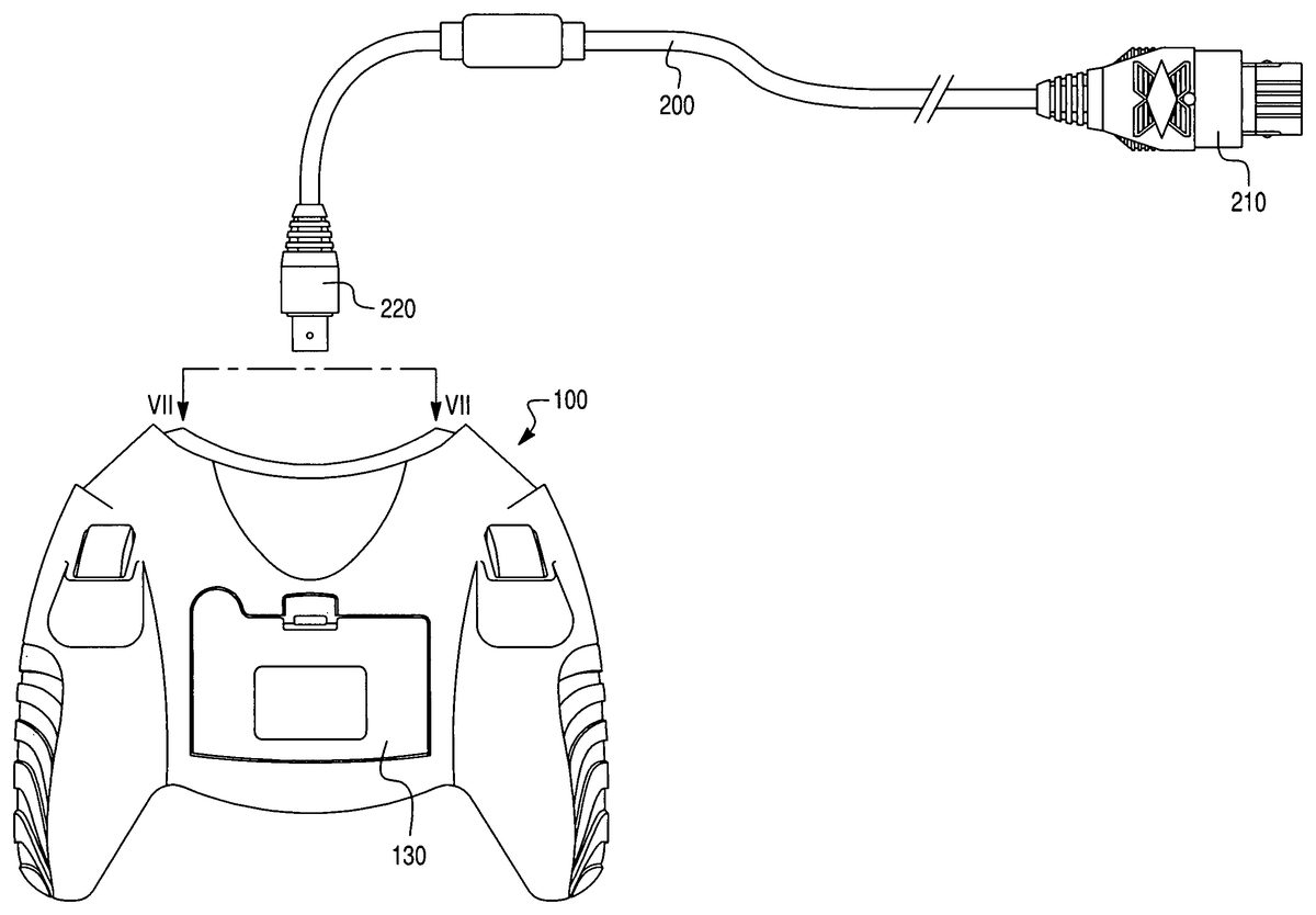
FIG. 6shows one embodiment of the recharging capability of the present invention; namely, a communication cable200facilitates communication with a stand-alone computer gaming console54is also provided to recharge the battery pack. The communication cable200is adapted to interface with the controller ports of the game console54at the first end plug210and to interface with the controller100at the second end controller cable plug220at the controller cable port150. See controller cable port150shown inFIG. 7. When the rechargeable batteries130shown inFIG. 6need to be recharged, the cable200can be plugged into both the console54and the controller100to recharge the batteries or battery pack130. The cable200also delivers control signal between the controller100and the game console54. In this case, it is possible to facilitate communication between the game console54and the controller100while recharging the batteries. In this embodiment, the wireless controller functions as a conventional wired controller to facilitate play while charging. SeeFIGS. 11 and 12.
FIG. 8shows an alternate system for charging the batteries of the controller where a power plug300delivers a charging signal from the wireless adapter350to the controller100. As known in the art, the conventional game console54may be converted for wireless communication by the adapter350which interfaces with the game console54at the console plug360which fits into the controller port of the game console54. The wireless controller100sends and received wireless signals to and from the receiver unit351, which signals are then transmitted to the game console through the controller port of the game console54. The receiver unit351is provided with a power jack352that receives the power plug310, and the other end320of the power plug is connected to the controller1000at a charging port190shown inFIG. 9. In this embodiment, the wireless controller functions as a wireless controller that communicates with the wireless transmitter/receiver unit351during the charging operation. SeeFIGS. 13 and 14.
This invention also envisions a combination of the features ofFIGS. 6–9, where the wireless controller100may include both the controller cable port150(seeFIG. 7) as well as the power charging port190(seeFIG. 9) to provide a versatile charging arrangement that permits both wired or wireless communication during the charging operation.
Thus, the controller100has the ability to communicate with the gaming console through dual channels. First, the controller has wireless transmission/receiver circuitry to wirelessly communicate to the gaming platform via the receiver/transmitter unit350and establish wireless two-way communication there between. Circuitry for the wired connection is also provided to allow direct connection via controller cable200shown inFIGS. 6 and 7. The wired circuitry may include a simple detection circuit, detecting the voltage supplied by the console via cable200to select transmission through the wired circuitry. This detection isolates the wireless transmission circuitry during said connection. Furthermore, the detection circuitry shunts/diverts voltage to the recharging circuitry to facilitate charging of the batteries. SeeFIGS. 10–15. Thus the ability to use multiple sources of voltage (through direct coupling to gaming platform, connection to wireless receiver350, or to a dedicated voltage source such as a conventional converter) coupled with the capability to communicate to the game platform through dual mediums (wired or wireless) affords tremendous flexibility and convenient to the user. For example, when the batteries are low, the player may still use the wireless controller via cable200and simultaneous play and recharge the battery. Thus, a player need not invest in additional wired controller as a back up for times when the batteries run out. Furthermore, the receiver unit350may be formed as a cradle unit corresponding to a shape of the controller to both provide a storage bay for the wireless controller and provide a physical direct connection to charge the battery pack avoiding the necessity for cable300. Such an arrangement provides an incentive to maintain the controller in this dedicated location and ensures that the batteries within the controller are always sufficiently charged to facilitate play and thus avoid recharging down time.
The controller100also has dual sources for recharging the batter pack. As previously mentioned, voltage may be drawn from voltage supplied through the wired cable200coupled directly to the gaming platform. However, controller100may also be provided with supplemental charge port to be connected to an alternate voltage source such as a dedicated power cable300through a connection to the adapter receiver unit350or from another power source.
Although the power plug300is shown as a separate cord, it will be understood by those of skill in the art that the power plug300may be integrated into the wireless adapter unit350. Similarly, the adapter unit350may be formed as a cradle for the controller such that the controller may be electrically connected to the adapter unit by sitting directly on the adapter when the controller is not being used. In this case, the battery charge port106(seeFIG. 4) mates directly with a jack on the adapter351. When cradled in this manner, the controller batteries may be recharged without connecting or disconnecting separate cables. The controller simply cradles with the adapter unit for the purpose of recharging the controller batteries130.
It is also noted that the present invention provides a special safety device (e.g., charging circuit activation switch102) that prevents accidental charging of disposable batteries through the controller charging port. The charging circuitry is “closed” when the specially designed battery pack is mounted to the controller by a mechanical actuator that physically closes a switch in the recharging circuit. SeeFIGS. 10–15.
It will also be apparent to those of skill in the art that the detachable controller cable shown inFIGS. 6 and 8provides alternative means of power with simultaneous two-way communication even when batteries are not available.
The invention also envisions an idle sleep mode for the battery-powered controller to conserve power when the controller is not is use. Likewise, the smart circuit design of this invention detects when power from detachable controller cable is available in order to isolate and preserve battery power.
Moreover, the invention allows the use of either disposable batteries or a rechargeable battery pack.
While the foregoing invention has been shown and described with reference to specific embodiments, it will be understood by those of skill in the art that various changes in form and detail may be made therein without departing from the spirit and scope of the present invention.
Claims
- A battery recharging system for a wireless computer game controller, comprising: at least one rechargeable battery adapted to be electrically connected to said wireless computer game controller;a wireless adapter that converts the game console into a wireless transmitter/receiver by sending and receiving wireless control signals with said wireless computer game controller and delivering said control signals to a control port of a game console;at least one battery charge port for electrically connecting a power source to recharge said at least one rechargeable battery;at least one power cable for delivering power from one of said wireless adapter and said game console to said rechargeable battery while the at least one rechargeable battery is installed on the controller, wherein said rechargeable battery may be recharged through the controller while the controller sends and receives wireless control signals with said game console.
- The system of claim 1 , wherein said power cable is configured to deliver power directly from said wireless adapter to said at least one battery charge port.
- The system of claim 1 , wherein said power cable is configured to connect to said game console through a game port.
- The system of claim 1 , wherein said controller communicates with said game console solely by wireless communication through said adapter.
- The system of claim 1 , further comprising a detection circuit for detecting a voltage supplied via said at least one power cable to initiate charging of said rechargeable battery.
Disclaimer: Data collected from the USPTO and may be malformed, incomplete, and/or otherwise inaccurate.