U.S. Pat. No. 6,971,957
GAME SYSTEM AND PROGRAM USING A SHADOW VOLUME TO DISPLAY A SHADOW OF AN OBJECT IN A THREE DIMENSIONAL VIDEO GAME
AssigneeNintendo Co., Ltd.
Issue DateApril 8, 2003
Illustrative Figure
Abstract
A DVD-ROM stores a plurality of shadow volume data corresponding to respective attitudes of an object which casts a shadow. A CPU sets a shadow volume corresponding to the attitude of the object by performing interpolation based on the shadow volume data as necessary. Based on the thus-set shadow volume, a GPU determines a shadow region using a stencil buffer. Based on the determined results, the GPU updates luminance information of each pixel stored in a color buffer. According to this configuration, when a game system uses the shadow volume to draw a shadow, it is possible to reduce the processing load caused by setting the shadow volume while drawing a more realistic shadow corresponding to the attitude of the object which casts the shadow.
Description
DESCRIPTION OF THE PREFERRED EMBODIMENTS FIG. 1is an external view illustrating the configuration of a game system according to an embodiment of the present invention.FIG. 2is a block diagram of the game system illustrated inFIG. 1. As shown inFIGS. 1 and 2, the game system includes the main body of a game machine100, a DVD-ROM300, and a controller200. The main body of the game machine100is connected to a loudspeaker600and a TV monitor500. Additionally, an external memory card400is provided to the game system as necessary. The DVD-ROM300and the external memory card400are removably loaded into the main body of the game machine100. The controller200is connected via a communication cable to any one of a plurality of controller port connectors (four connectors are shown inFIG. 1) provided in the main body of the game machine100. The TV monitor500and the loudspeaker600are connected to the main body of the game machine100via an AV cable or the like. It should be noted that the communication between the main body of the game machine100and the controller200may be performed wirelessly. Each part of the game system will be described in more detail below with reference toFIG. 2. The DVD-ROM300fixedly stores a game program and data regarding the game, such as character data. When the player plays the game, the DVD-ROM300is loaded into the main body of the game machine100. As means for storing the game program, etc., an external storage medium, such as a CD-ROM, an MO, a memory card, a ROM cartridge, or the like, may be used instead of using the DVD-ROM300. The external memory card400is formed by a rewritable storage medium, such as a flash memory or the like, and stores data, e.g. save data in a game. The main body of the game machine100reads the game program stored in the DVD-ROM300and performs game processing. ...
DESCRIPTION OF THE PREFERRED EMBODIMENTS
FIG. 1is an external view illustrating the configuration of a game system according to an embodiment of the present invention.FIG. 2is a block diagram of the game system illustrated inFIG. 1. As shown inFIGS. 1 and 2, the game system includes the main body of a game machine100, a DVD-ROM300, and a controller200. The main body of the game machine100is connected to a loudspeaker600and a TV monitor500. Additionally, an external memory card400is provided to the game system as necessary. The DVD-ROM300and the external memory card400are removably loaded into the main body of the game machine100. The controller200is connected via a communication cable to any one of a plurality of controller port connectors (four connectors are shown inFIG. 1) provided in the main body of the game machine100. The TV monitor500and the loudspeaker600are connected to the main body of the game machine100via an AV cable or the like. It should be noted that the communication between the main body of the game machine100and the controller200may be performed wirelessly. Each part of the game system will be described in more detail below with reference toFIG. 2.
The DVD-ROM300fixedly stores a game program and data regarding the game, such as character data. When the player plays the game, the DVD-ROM300is loaded into the main body of the game machine100. As means for storing the game program, etc., an external storage medium, such as a CD-ROM, an MO, a memory card, a ROM cartridge, or the like, may be used instead of using the DVD-ROM300.
The external memory card400is formed by a rewritable storage medium, such as a flash memory or the like, and stores data, e.g. save data in a game.
The main body of the game machine100reads the game program stored in the DVD-ROM300and performs game processing.
The controller200is an input device for the player to input information related to game operations and has a plurality of operating switches. The controller200outputs operation data to the main body of the game machine100in response to the player pressing an operating switch, for example.
The TV monitor500displays image data output by the main body of the game machine100on the display screen. The loudspeaker600is typically included in the TV monitor500and outputs audio in the game output by the main body of the game machine100.
The configuration of the main body of the game machine100will now be described. InFIG. 2, the main body of the game machine100includes a CPU10and a memory controller20connected thereto. In the main body of the game machine100, the memory controller20is also connected to a graphics processing unit (GPU)11, a main memory17, a DSP18, and various interfaces (I/F)21–24and26. The memory controller20controls data transfer between these elements.
In order to start the game, firstly, a DVD drive25drives the DVD-ROM300loaded into the main body of the game machine100. The game program stored in the DVD-ROM300is read by the main memory17via the DVD disc I/F26and the memory controller20. When the program in the main memory17is executed by the CPU10, the game is started. After the start of the game, the player performs input operations, such as game operations, by using operation switches of the controller200. In response to the input operations by the player, the controller200outputs operation data to the main body of the game machine100. The operation data output by the controller200is input to the CPU10via the controller I/F21and the memory controller20. The CPU10performs game processing in accordance with the input operation data. For example, the GPU11and the DSP18are used for creating image data during game processing. A sub-memory19is used when the DSP18performs prescribed processing.
The GPU11includes a geometric unit12and a rendering unit13and is connected to a memory exclusively used for image processing. The memory exclusively used for image processing is used as, for example, a color buffer14, a Z-buffer15, or a stencil buffer16. The geometry unit12performs arithmetic processing regarding coordinates of a three-dimensional model related to an object or graphics placed in a game space, which is a virtual three-dimensional space, (e.g., an object formed by polygons). Examples of such arithmetic processing include the rotation, scaling, and deformation of the three-dimensional model, and coordinate conversions from the world coordinate system to the viewing coordinate system or screen coordinate system. Based on a prescribed texture, the rendering unit13creates a game image by writing to the color buffer14color data (RGB data) for each pixel of the three-dimensional model projected onto the screen coordinate system. The color buffer14is a memory region reserved for holding game image data (RGB data) created by the rendering unit13. The Z-buffer15is a memory region reserved for holding depth information regarding the depth of field from a viewpoint which is lost when the conversion from the three-dimensional viewing coordinate to the two-dimensional screen coordinate is performed. The stencil buffer16is a memory region reserved for performing determination regarding a shadow region by using the shadow volume which will be described later. The GPU11uses these buffers to create image data to be displayed on the TV monitor500and suitably outputs the image data to the TV monitor500via the memory controller20and the video I/F22. Audio data created by the CPU10when the game program is executed is output via the memory controller20through the audio I/F24to the loudspeaker600. In the present embodiment, hardware configuration includes the additional memory exclusively used for image processing, but the present invention is not limited to this. For example, a scheme in which part of the main memory17is used as a memory for image processing, (UMA: Unified Memory Architecture), may be employed.
Hereinafter, the operation of the present embodiment will be described.
In the present embodiment, as shadow volume data, a plurality of shadow volumes are prepared beforehand for an object which casts a shadow. The term “shadow volume” defines a space over which an object casts a shadow, or a space in which light from the light source is blocked by such an object. By using the shadow volume, it is possible to correctly display a shadow which is cast over complicated topographic features. Shadow drawing processing which uses the shadow volume will be described below with reference to various drawings.
As shown inFIG. 3, in a topographic object, a shadow is created in a region where an object which casts a shadow overlaps with the topographic object (hereinafter, referred to as the “shadow region”). InFIG. 3, although the case where parallel light is used is illustrated, the shadow is similarly created in the case where a point source of light is used. The shadow region can be easily determined by using a stencil buffer. As a general technique for determining the shadow region by using the stencil buffer, as shown inFIG. 4, firstly, (a) front side surfaces of the shadow volume are drawn with reference to the Z-buffer (in this case, each pixel value in the stencil buffer is incremented instead of updating color information for each pixel in the color buffer), and then (b) back side surfaces of the shadow volume are drawn with reference to the Z-buffer (in this case, each pixel value in the stencil buffer is decremented instead of updating the color information for each pixel in the color buffer). Consequently, when the initial value is “0”, each pixel value in the stencil buffer becomes “1” in the portion corresponding to the shadow region and becomes “0” in the other portions. The color information in the color buffer is changed based on each pixel value in the stencil buffer. For example, among luminance information stored in each pixel of the color buffer based on the texture of the topographic object, values of luminance information corresponding to the shadow region are reduced. As a result, a realistic shadow can be displayed.
In the present embodiment, a plurality of shadow volume data corresponding to attitudes of the object which casts a shadow are prepared beforehand. The shadow volume is set based on these shadow volume data. The thus-set shadow volume is used to draw a shadow in the game space.
In the present embodiment, by way of example, the case where the object which casts a shadow is rotated about a prescribed axis (in this case, the Z-axis in the object coordinate system; in some portions of the following description, “the Z-axis in the object coordinate system” is simply referred to as the “Z-axis”) in the range between +90° and −90° from a reference position will be described. In the actual game, e.g., a cart race game, the above-mentioned exemplary case corresponds to the case where the cart is rotated about a vector along a progress direction of the cart, i.e., the cart is laterally turned, (in the present embodiment, the right-handed rotation when facing the progress direction is a positive direction). The attitude of the object is represented by an angle of rotation about the Z-axis.
In the present embodiment, seven shadow volume data are prepared beforehand for an object which casts a shadow and respective shadow volume data correspond to angles of rotation of the object around the Z-axis, 0°, 30°, 60°, 90°, −30°, −60°, and −90°, where the basic attitude of the object corresponds to 0°.FIG. 5illustrates sets of shadow volumes and shadows in the game space which respectively correspond to the cases where angles of rotation of the object around the Z-axis are 0°, 30°, 60°, and 90°.FIG. 6illustrates sets of shadow volumes and shadows in the game space which respectively correspond to the case where angles of rotation of the object around the Z-axis are 0°, −30°, −60°, and −90°. It should be noted that the shadows illustrated inFIGS. 5 and 6are cast over a topographic object (an object over which a shadow is cast) which is a plane.
In the above-described method illustrated inFIG. 14, even if the object is rotated, the shadow in the game space does not change. However, according to the present invention, as shown inFIGS. 5 and 6, different shadow volumes are used in accordance with angles of rotation of the object, and therefore realistic shadows are created in accordance with the angles of rotation of the object.
The shadow volume data to be prepared beforehand may be faithfully created based on the shape of the object or may be roughly created based on the unevenness of the shape of the object.
The shadow volume data is previously stored in, for example, the DVD-ROM300(all the shadow volume data corresponding to the angles of rotation, 0°, 30°, 60°, 90°, −30°, −60°, and −90°, are stored), and read out into a memory of the game apparatus by the DVD drive25, as necessary, so as to be used for shadow volume setting processing. In the present embodiment, shadow volume data for seven angles of rotation (0°, 30°, 60°, 90°, −30°, −60°, and −90°) is previously stored in the DVD-ROM300, but the present invention is not limited to this. The number of angles of rotation to which the stored shadow volume data correspond may be at least two.FIG. 7illustrates shadow volume data prepared beforehand for an object (in this case, object A). InFIG. 7, as the shadow volume data for object A, basic shadow volume data and deformation offset data are prepared beforehand. The basic shadow volume data defines the shape of the shadow volume corresponding to the angle of rotation of object A around the Z-axis, which is 0°, by coordinates of each vertex of the shadow volume (coordinates in the object coordinate system). The deformation offset data defines the respective shapes of the shadow volumes corresponding to angles of rotation of object A around the Z-axis, 30°, 60°, 90°, −30°, −60°, and −90°, by using offset data referencing the basic shadow volume data. For example, in the case where vertex A of the basic shadow volume data has coordinates (Xa, Ya, Za) and respective offset values of the coordinates of vertex A of the shadow volume for the angle of rotation of 30° are represented by (ΔXa30, ΔYa30, ΔZa30) with respect to the coordinates of the basic shadow volume data, vertex A of the shadow volume for the angle of rotation of 30° has coordinates (Xa+ΔXa30, Ya30ΔYa30, Za+ΔZa30).
FIG. 8specifically illustrates the relationship between the deformation offset data and shapes of actual shadow volumes. Vertex B of the basic shadow volume has coordinates (0, 10, 2). Coordinates of vertex B of the shadow volume for the angle of rotation of 30° are obtained by adding respective components of the offset value ΔB30=(1, 0, 0) of vertex B for the angle of rotation of 30° to a corresponding component of coordinates (0, 10, 2) of vertex B of the basic shadow volume data, i.e., vertex B of the shadow volume for the angle of rotation of 30° has coordinates (1, 10, 2). Coordinates of vertex B of the shadow volume for the angle of rotation of 60° are obtained by adding respective components of the offset value ΔB60=(3, 0, 0) of vertex B for the angle of rotation of 60° to a corresponding component of coordinates (0, 10, 2) of vertex B of the basic shadow volume data, i.e., vertex B of the shadow volume for the angle of rotation of 60° has coordinates (3, 10, 2). Coordinates of vertex B of the shadow volume for the angle of rotation of 90° are obtained by adding respective components of the offset value ΔB90=(4, 0, 0) of vertex B for the angle of rotation of 90° to a corresponding component of coordinates (0, 10, 2) of vertex B of the basic shadow volume data, i.e., vertex B of the shadow volume for the angle of rotation of 90° has coordinates (4, 10, 2). Although not shown in the figure, coordinates of vertex B for the angle of rotation of −30°, −60°, or −90° are determined in the same manner.
InFIG. 8, the shape of a shadow volume is defined by ten vertexes, i.e., vertexes A–J. However, the locations and number of the vertexes are freely determined. In the example shown inFIG. 8, the way the shadow changes in accordance with the rotation of the triangular prism is simple, and therefore all the movements of vertexes are seen only in the X-axis direction. However, the present invention is not limited to this, and settings may be made such that each vertex moves along any direction in accordance with the rotation of the object.
As described above, in the present embodiment, offset data referencing the basic shadow volume data are prepared as the shadow volume data corresponding to the angles of rotation of the object, 30°, 60°, 90°, −30°, −60°, and −90°, but the present invention is not limited to this. Shadow volume data, which define shapes of shadow volumes by actual coordinates of vertexes as in the case of the basic shadow volume, may be used as the shadow volume data corresponding to angles of rotation of the object, 30°, 60°, 90°, −30°, −60°, and −90°.
As described above, when the angle of rotation of the object which casts a shadow is 0°, 30°, 60°, 90°, −30°, −60°, or −90°, it is possible to easily set the shadow volume based on the shadow volume data as shown inFIG. 7. A method for setting shadow volumes for the object which casts a shadow will now be described with respect to the case where the angle of rotation of the object around the Z-axis is an angle other than those described above.
In the present embodiment, when the angle of rotation of the object which casts a shadow is an angle other than 0°, 30°, 60°, 90°, −30°, −60°, and −90°, (e.g., 15°, −40°, etc.), the shadow volume is dynamically set by linear interpolation based on the prepared shadow volume data. The linear interpolation will be more specifically described below.
When the angle of rotation of the object which casts a shadow is α°, coordinates of vertex A of the shadow volume is obtained by calculating the offset value ΔAαwhen the angle of rotation of the object which casts a shadow is α°. The offset value ΔAαis calculated by expressions shown below. It should be noted that coordinates of vertexes other than vertex A (i.e., vertexes B, C, . . . ) can be calculated in the same manner.
(1) when 0<α<30,
ΔAα=ΔA30×α/30;
(2) when 30<α<60,
ΔAα={ΔA30×(60−α)+ΔA60×(α−30)}/30;
(3) when 60<α<90,
ΔAα={ΔA60×(90−α)+ΔA90×(α−60)}/30;
(4) when −30<α<0,
ΔAα=−ΔA−30×α/30;
(5) when −60<α<−30,
ΔAα=−{ΔA−30×(−60−α)+ΔA−60×(α+30)}/30; and
(6) when −90<α<60,
ΔAα=−{ΔA−60×(−90−α)+ΔA−90×(α+60)}/30;
In this manner, when there is no prepared shadow volume data corresponding to an angle of rotation of the object which casts a shadow, the shadow volume data corresponding to the angle of rotation of the object which casts a shadow is set by linear interpolation based on two of the prepared shadow volume data. It should be noted that the type of interpolation is not limited to the linear interpolation, and any function expression can be used for interpolation. However, it is advantageous to use the linear interpolation in that calculation for setting shadow volumes can be simplified.
Once the shadow volume corresponding to the angle of rotation of the object which casts a shadow is set in the above -described manner, the shadow is drawn based on the set shadow volume. Consequently, it is possible to display a realistic shadow in accordance with the attitude of the object which casts a shadow.
An operation of the CPU10or the GPU11according to the present embodiment will now be described with reference to the flowcharts illustrated inFIGS. 9–12.
Referring toFIG. 9, the main processing of a game is described. Firstly, initial processing, e.g., initialization processing of variables, displaying of the initial state screen, etc., is performed (step S1). Next, when the game is started, processing of operation inputs by the player is accepted (step S2), and the coordinates and attitude of a player object are updated based on the operation inputs by the player and various factors in the game (e.g., forces applied by contacts between objects, by the ground, etc.) (step S3). After step S3, based on a program for controlling movements of a non-player object, which is stored in the DVD-ROM300, processing for controlling movements of the non-player object is performed (step S4), and the coordinates and attitude of the non-player object are updated (step S5). After step S5, other game processings (e.g., combat processing, menu processing, etc.) are performed (step S6), and thereafter drawing processing is performed (step S7). The drawing processing will be described later with reference toFIG. 10. After step S7, whether or not the game is over is determined in step S8. If the game is over, the game processing is terminated. If it is not over yet, the procedure returns to step S1to repeat the processing of step S1–S8.
Referring toFIG. 10, the drawing processing of step S7illustrated inFIG. 9will now be described. When the drawing processing is started, the GPU11compares depth information of the object over which a shadow is cast (the topographic object) with the value of the Z-buffer15and suitably updates the value of the Z-buffer15while drawing the object over which a shadow is cast in the color buffer14(step S11). When drawing of the object over which a shadow is cast is completed, the CPU10performs shadow volume setting processing for setting shadow volumes of objects which cast a shadow (the player and non-player objects) (step S12). The details of the shadow volume setting processing will be described later. When the shadow volume setting processing is completed, the GPU11performs shadow drawing processing based on the shadow volumes set by the shadow volume setting processing (step S13). The details of the shadow drawing processing will be described later. When the shadow drawing processing is completed, the GPU11compares depth information of the object which casts a shadow with the value of the Z-buffer15and suitably updates the value of the Z-buffer15while drawing the object which casts a shadow in the color buffer14(step S14). When drawing of the object which casts a shadow is completed, the drawing process is terminated.
Referring toFIG. 11, the shadow volume setting process of step S12illustrated inFIG. 10will now be described. When the shadow volume setting process is started, the CPU10calculates the angle of rotation α of the object, which casts a shadow, around the Z-axis (step S121). Next, the CPU10reads basic shadow volume data (step S122). Then, the CPU10calculates a deformation offset corresponding to the angle of rotation α calculated at step S121(step S123). Specifically, in the case where the deformation offset data corresponding to the angle of rotation α is prepared beforehand, the prepared data is read. Otherwise, linear interpolation is performed based on two shadow volume data corresponding to angles of rotation in the neighborhood of the prepared angle of rotation α, so as to calculate the deformation offset corresponding to the angle of rotation α (e.g., the aforementioned ΔAαor the like). When calculating of the deformation offset corresponding to the angle of rotation α is completed, the shadow volume is set based on the deformation offset and the basic shadow volume data (i.e., by deforming the basic shadow volume based on the deformation offset) (step S124). When setting of the shadow volume is completed, the procedure returns to the drawing processing illustrated inFIG. 10.
Referring toFIG. 12, the shadow drawing processing of step S13illustrated inFIG. 10will now be described. When the shadow drawing process is started, the GPU11initially clears each pixel value in the stencil buffer16, which is a buffer used for determining a shadow (step S131), to 0 and then draws the front side surfaces of the shadow volume with reference to the Z-buffer15(step S132). In this case, each pixel value in the stencil buffer16is incremented instead of writing color information to the color buffer14. Next, the back side surfaces of the shadow volume is drawn with reference to the Z-buffer15(step S133). In this case, each pixel value in the stencil buffer16is decremented instead of writing color information to the color buffer14. Based on the thus-written value of each pixel in the stencil buffer16, the GPU11changes luminance information of each pixel in the color buffer14(step S134). When the shadow drawing processing is completed in this manner, the procedure returns to the drawing processing illustrated inFIG. 10.
As described above, in the present embodiment, a plurality of shadow volume data corresponding to several attitudes of the object which casts a shadow are prepared beforehand, and interpolation is performed based on these shadow volume data as necessary, thereby setting the shadow volume corresponding to the attitude of the object. Accordingly, for example, in game processing, it is not necessary to set the shadow volume based on the outline of the object which casts a shadow or edges of a plurality of polygons forming the object each time the attitude of the object is changed. As a result, the processing load of drawing a shadow can be reduced. Moreover, the shadow volume is used for drawing a shadow, and therefore it is possible to draw a more realistic shadow which reflects the unevenness of the object over which a shadow is cast.
In the present embodiment, the game program is supplied to the main body of the game machine100via the DVD-ROM300, but the present invention is not limited to this. The game program may be stored in any computer-readable recording medium other than the DVD-ROM300, e.g., a CD-ROM, an MO, a memory card, a ROM cartridge, or the like, and supplied to the main body of game machine100via such a medium. Alternatively, the game program may be previously incorporated into the main body of game machine100. Still alternatively, the game program may be supplied to the main body of the game machine100via a communication line.
Furthermore, in the present embodiment, the GPU11performs the drawing process, etc. Such processings may be performed by the CPU10.
Further still, in the present embodiment, the case where shadows created by using parallel light are drawn is described, but the present invention is not limited to this. The present invention is applicable to the case where shadows created by using, for example, light from a point source of light.
Further still, in the present embodiment, the attitude of the object which casts a shadow is changed by rotation around the Z-axis. The present invention is also applicable to the case where the object which casts a shadow rotates about a plurality of axes. In such a case, for example, shadow volume data is prepared beforehand for each combination of the angle of rotation around the Z-axis and the angle of rotation around the X-axis, and the shadow volumes are set based on these shadow volume data. This allows shadows to be drawn in accordance with rotation of the object which casts a shadow around the plurality of axes.
Further still, in the present embodiment, the attitude of the object which casts a shadow is changed by rotation around the Z-axis. The present invention is also applicable to the case where the shape of the object itself is changed. In such a case, for example, a plurality of shadow volume data corresponding to a plurality of deformation states are prepared beforehand, and the shadow volumes are set based on these shadow volume data. This allows shadows to be drawn in accordance with deformation of the object which casts a shadow.
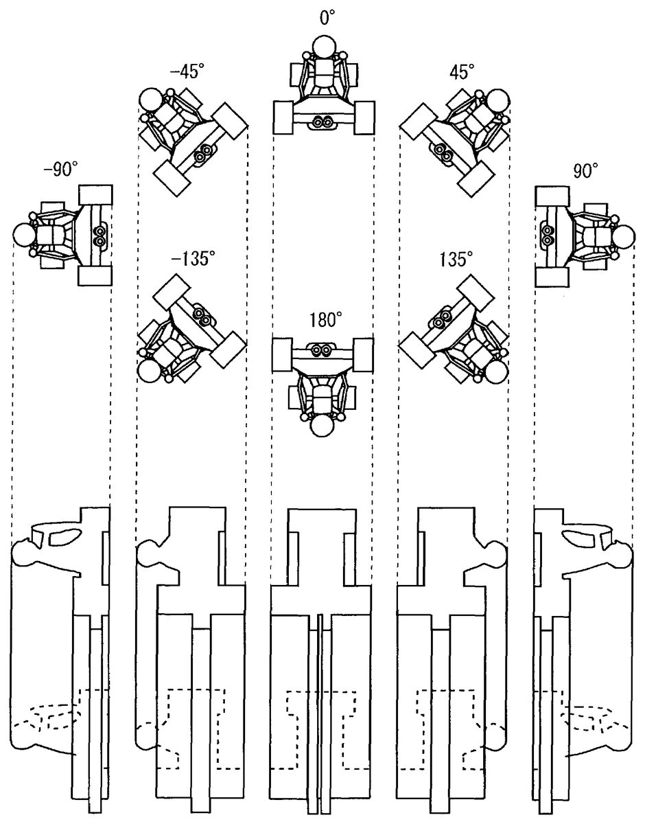
Further still, the symmetry of the attitude of the object which casts a shadow can be utilized to reduce the number of shadow volume data to be previously stored in the DVD-ROM300or the like. Such contrivance is described below with reference toFIG. 13.
FIG. 13is a diagram illustrating attitudes of a character object in a cart race game and shapes of a shadow volume in the case where the object is rotated about an axis along a progress direction of the cart. In this case, the character object is irradiated with parallel light from directly thereabove (from vertically above the cart with respect to the progress direction). In the example ofFIG. 13, shapes of the shadow volume are identical to each other with respect to the angles of rotation of 0° and 180°. Further, shapes of the shadow volume are identical to each other with respect to the angles of rotation of 45° and 135°. Furthermore, shapes of the shadow volume are identical to each other with respect to the angles of rotation of −45° and 135°. Accordingly, shadow volume data for the angles of rotation of 45°, 0°, and −45° can be commonly used as shadow volume data for the angles of rotation of 135°, 180°, and −135°, respectively. More generally, if shadow volume data corresponding to rotation halfway around the rotation axis (in this case, −90° to 90°) is prepared beforehand, shadow volume corresponding to rotation all the way around the rotation axis (i.e., 360°) can be set. However, this is only applicable to the case where shapes of the object which casts a shadow are symmetric with respect to a plane which includes the rotation axis.
InFIG. 13, comparing the shadow volume for the angle of rotation of 45° and the shadow volume for the angle of rotation of −135°, it is found that these shadow volumes are in reversed relationship to each other with respect to the right and left directions in the figure. The same can be said of the relationship between the shadow volume for the angle of rotation of 90° and the shadow volume for the angle of rotation of −90°. Moreover, the same can be said of the relationship between the shadow volume for the angle of rotation of 135° and the shadow volume for the angle of rotation of −45° Accordingly, the shadow volume data for the angles of rotation −135°, −90°, and −45° can be commonly used for the shadow volume data for the angles of rotation 45°, −90°, and 135°, respectively. That is, a single shadow volume can be used for two attitudes differing from each other by 180° in the angle of rotation. However, in such a case, for setting the shadow volume, it is necessary to additionally perform simple calculations for reversing the shape of the shadow volume (e.g., conversion of offset values, conversion of coordinates of vertexes, etc.).
By combining the above two contrivances together, it is possible to further reduce the number of shadow volume data to be previously stored. Specifically, inFIG. 13, the shadow volume data for the angle of rotation of 0° can be used for the shadow volume data for the angle of rotation of 180°. Further, the shadow volume data for the angle of rotation of 45° can be used for the shadow volumes for the angles of rotation of 135°, −135°, and −45°. Furthermore, the shadow volume data for the angle of rotation of 90° can be used for the shadow volume for the angle of rotation of −90°. That is, if the shadow volume data corresponding to a quarter way around the rotation axis (in this case, 0° to 90°) is prepared, it is possible to set shadow volumes corresponding to all the way around the rotation axis (i.e., 360°).
While the invention has been described in detail, the foregoing description is in all aspects illustrative and not restrictive. It is understood that numerous other modifications and variations can be devised without departing from the scope of the invention.
Claims
- A game system for displaying a shadow of an object in a three-dimensional game space by using a shadow volume, the game system comprising: an attitude changing processing mechanism for changing an attitude of the object;first shadow volume data storage locations having stored therein first shadow volume data corresponding to a first attitude of the object;second shadow volume data storage locations having stored therein second volume data corresponding to a second attitude of the object which is different from the first attitude;a shadow volume setting processing mechanism for setting the shadow volume based on the first shadow volume data when the attitude of the object, which is changed by the attitude changing mechanism, at a certain point in time corresponds with the first attitude and for setting the shadow volume based on the second shadow volume data when the attitude of the object at the certain point in time corresponds with the second attitude;and a shadow drawing processing mechanism for drawing a shadow of the object at the certain point in time based on the shadow volume set by the shadow volume setting processing mechanism.
- The game system according to claim 1 , wherein the shadow volume setting processing mechanism sets the shadow volume by interpolation based on the first shadow volume data and the second shadow volume data when the attitude of the object at the certain point in time is different from both the first attitude and the second attitude.
- The game system according to claim 2 , wherein the interpolation is linear interpolation.
- The game system according to claim 1 , wherein the second shadow volume data is offset data referencing the first shadow volume data.
- The game system according to claim 1 , wherein: the attitude changing processing mechanism rotates the object about a prescribed axis in an object coordinate system;the second attitude is an attitude of the object rotated around the prescribed axis by a certain angle from the first attitude;and the shadow volume setting processing mechanism sets the shadow volume based on the angle of rotation of the object around the prescribed axis.
- The game system according to claim 5 , wherein when the attitude of the object at the certain point in time is equal to a third attitude which is in a prescribed relationship to the first attitude, the shadow volume setting processing mechanism sets the shadow volume by using the first shadow volume data as shadow volume data corresponding to the third attitude.
- The game system according to claim 6 , wherein shapes of the object are symmetric with respect to a plane including the prescribed axis.
- The game system according to claim 6 , wherein the third attitude is an attitude of the object rotated around the prescribed axis by 180° from the first attitude.
- A computer readable medium encoded with a game program executed by a computer in a game apparatus for displaying a shadow of an object in a three-dimensional game space by using a shadow volume, the game program causing the computer to execute: an attitude changing step for changing an attitude of the object;a first shadow volume data reading step for reading a previously stored first shadow volume data corresponding to a first attitude of the object;a second shadow volume data reading step for reading a previously stored second shadow volume data corresponding to a second attitude of the object which is different from the first attitude;a shadow volume setting step for setting the shadow volume based on the first shadow volume data when the attitude of the object, which is changed by the attitude changing step, at a certain point in time corresponds with the first attitude and for setting the shadow volume based on the second shadow volume data when the attitude of the object at the certain point in time corresponds with the second attitude;and a shadow drawing step for drawing a shadow of the object at the certain point in time based on the shadow volume set by the shadow volume setting step.
- The computer readable medium according to claim 9 , wherein when the attitude of the object at the certain point in time is different from both the first attitude and the second attitude, the shadow volume setting step sets the shadow volume by interpolation based on the first shadow volume data and the second shadow volume data.
- The computer readable medium according to claim 10 , wherein the interpolation is linear interpolation.
- The computer readable medium according to claim 9 , wherein the second shadow volume data is offset data referencing the first shadow volume data.
- The computer readable medium according to claim 9 , wherein: the attitude changing step rotates the object about a prescribed axis in an object coordinate system;the second attitude is an attitude of the object rotated around the prescribed axis by a certain angle from the first attitude;and the shadow volume setting step sets the shadow volume based on the angle of rotation of the object around the prescribed axis.
- The computer readable medium according to claim 9 , wherein when the attitude of the object at the certain point in time is equal to a third attitude which is in a prescribed relationship to the first attitude, the shadow volume setting step sets the shadow volume by using the first shadow volume data, which is left unchanged or is suitably changed, as shadow volume data corresponding to the third attitude.
- The computer readable medium according to claim 14 , wherein shapes of the object are symmetric with respect to a plane including the prescribed axis.
- The computer readable medium according to claim 14 , wherein the third attitude is an attitude of the object rotated around the prescribed axis by 180° from the first attitude.
Disclaimer: Data collected from the USPTO and may be malformed, incomplete, and/or otherwise inaccurate.