U.S. Pat. No. 6,955,598
DESIGNATED POSITION DETECTOR AND GAME CONTROLLER UTILIZING THE SAME
AssigneeAlps Electronics Co., Ltd.
Issue DateMay 21, 2001
Illustrative Figure
Abstract
A controller is provided with an artificial retina chip. The artificial retina chip is connected to a display unit via a game machine body. Before starting the game, the artificial retina chip is instructed to recognize an image of frame of the display unit to store such image as the reference image. After starting the game, the controller is moved to recognize the image of frame of the display unit in order to detect the designated position by comparing the coordinate position data after the movement and the coordinate position data of the reference image.
Description
DETAILED DESCRIPTION OF THE PREFERRED EMBODIMENT FIG. 1is a block diagram illustrating a system structure of a gun controller for game machine of the present invention,FIG. 2is an explanatory diagram of the designated position detector,FIG. 3is a flowchart indicating the total process of the designated position detector,FIG. 4is a flowchart indicating the image process and frame recognizing process andFIG. 5is a flowchart indicating the communication process. The gun controller of the present invention illustrated inFIG. 1is comprised of a controller1as an operation member to be manually operated, a display unit (display)10utilizing a liquid crystal panel or the like and a game machine body (or a computer body installing a game software)20. The controller1is connected to the game machine body20with a predetermined cable and the game machine20is connected to a video terminal or the like of the display unit10via the predetermined cable. The display unit10may be used in multiple displays unlike the ordinary television receiver, which uses scanning lines, such as the existing display unit realizing a display with the scanning lines, a thin display unit utilizing a liquid crystal panel or a plasma display panel, a display screen utilizing a projector, and high definition television for next generation games in which timings of signals supplied to the scanning lines are different. The controller1can be formed with a cabinet shaped, for example, like a model-gun that is provided with a trigger2and an artificial retina chip3. With the operation of pulling the trigger2, a predetermined signal is sent to a game machine body20. The artificial retina chip3is constituted by integrating into one chip an artificial retina LSI (Large Scale Integrated Circuit)4as an image recognizing means, a CPU5functioning as a control unit, a ROM6, a RAM7, an input/output terminal (I/O)8and an interface (I/F)9, etc. The artificial retina LSI4is a chip that enables image ...
DETAILED DESCRIPTION OF THE PREFERRED EMBODIMENT
FIG. 1is a block diagram illustrating a system structure of a gun controller for game machine of the present invention,FIG. 2is an explanatory diagram of the designated position detector,FIG. 3is a flowchart indicating the total process of the designated position detector,FIG. 4is a flowchart indicating the image process and frame recognizing process andFIG. 5is a flowchart indicating the communication process.
The gun controller of the present invention illustrated inFIG. 1is comprised of a controller1as an operation member to be manually operated, a display unit (display)10utilizing a liquid crystal panel or the like and a game machine body (or a computer body installing a game software)20. The controller1is connected to the game machine body20with a predetermined cable and the game machine20is connected to a video terminal or the like of the display unit10via the predetermined cable.
The display unit10may be used in multiple displays unlike the ordinary television receiver, which uses scanning lines, such as the existing display unit realizing a display with the scanning lines, a thin display unit utilizing a liquid crystal panel or a plasma display panel, a display screen utilizing a projector, and high definition television for next generation games in which timings of signals supplied to the scanning lines are different.
The controller1can be formed with a cabinet shaped, for example, like a model-gun that is provided with a trigger2and an artificial retina chip3. With the operation of pulling the trigger2, a predetermined signal is sent to a game machine body20. The artificial retina chip3is constituted by integrating into one chip an artificial retina LSI (Large Scale Integrated Circuit)4as an image recognizing means, a CPU5functioning as a control unit, a ROM6, a RAM7, an input/output terminal (I/O)8and an interface (I/F)9, etc.
The artificial retina LSI4is a chip that enables image recognition and may also discriminate and adjust the shape and brightness of an object. This artificial retina LSI4is provided within a barrel (not shown) of the cabinet at the position for recognizing the object from within the barrel via the muzzle (not shown). Moreover, a lens (not shown) is provided at an area near the muzzle in the cabinet and this lens recognizes the enlarged display of the object recognized with the artificial retina LSI4.
Moreover, the artificial retina LSI4is connected with CPU5that is also connected with the ROM6and the RAM7and is further connected with the trigger2via the input/output terminal8. Predetermined programs or the like for starting and image recognition are read to the CPU5from the ROM6and the image data or the like stored by the artificial retina LSI4is stored in the RAM7. In addition, the CPU5is connected with the game machine body20with the predetermined interface9.
The game machine body20is provided, although not illustrated in the figure, with a driver to read CDs or DVDs in which game applications, for example, are recorded or with a control unit or the like to control the images.
When the controller1is driven, the initial setting is performed in the artificial retina chip3and thereafter a user performs the initial setting. The reference numeral13inFIG. 2indicates a region that can be recognized with the artificial retina chip3, while numeral14is a standard indicating a center position (+) of the region13. This standard14is set in matching with the position where a user views from an end point of the barrel. First, the user instructs the controller1to recognize the standard image and thereby the designated position is detected from the amount of change of the relative position of the image to be recognized next after the controller1is moved based on such reference image.
Namely, in the reference image recognizing process, an entire part of the display area11, for example, has a brightness different from that of the frame12of the display area10and is defined as a blue image, which the user is instructed to shoot by pulling the trigger2by directing the muzzle to the mark X displayed at the center of the display area11.
With the operations explained above, the frame12is recognized with the artificial retina chip3as the image indicated with the mark15A in FIG.2. The image15A indicates the shape of the boundary between the frame12and display area11. In this embodiment, the frame12surrounding the display area11is considered as the detection object and an image of the frame12as the detection object is considered as the reference image. Therefore, it is preferable for the frame12to have a color that contrasts with and can be easily discriminated in the brightness from the display area11. The frame12preferably has the colors of, for example, black and dark green or the like.
The image data of image15A is stored in the RAM7and is then used as the reference process data.
Upon start of the game, when the user pulls the trigger2after the muzzle of the controller1is directed to the target S1of the display area11, as illustrated inFIG. 1, for example, the muzzle is moved in the right lower direction from the reference position toward a corner of the display area10. In this case, the image of the frame12of the display unit10recognized with the artificial retina chip3is conditioned as indicated with the mark15B. Namely, the actually recognized image15B moves in the left upper direction opposed to the direction explained above and the standard14indicates the area near the right lower corner of the frame15B. The coordinate data of the reference image15A and the image15B after the movement are compared with each other, an amount of movement of the center to the image15B from the image15A is calculated with CPU5and the position data obtained by this calculation is sent to the game machine body20via the interface9. Accordingly, when the position data is matched with or included in the coordinate data of the image of the target S1displayed in the display area11, the image of the target S1is switched to the predetermined image or the point of game is added.
Moreover, when the trigger2is pulled while the muzzle of controller1is directed to the target S2inFIG. 1, the image of frame indicated with the mark15C inFIG. 2is recognized. In this case, the center of the reference image15A is located to the position outside the center of the image15C and the amount of movement to the image15C from the reference image15A is calculated with CPU5. When the calculated position data is matched with or included to the coordinate data of the target S2displayed in the display area11, the process or the like to give change to the image of the target S2is performed.
As explained above, the position designated on the display area11with the controller1can be detected. When the gun controller of the present invention is of the type requiring the operation to load a bullet, it is also possible to execute the loading of bullet when the trigger2is pulled while the muzzle of controller1is directed to the outside of the display area11.
The method of detecting the designated position with the gun controller of the present invention will then be explained below.
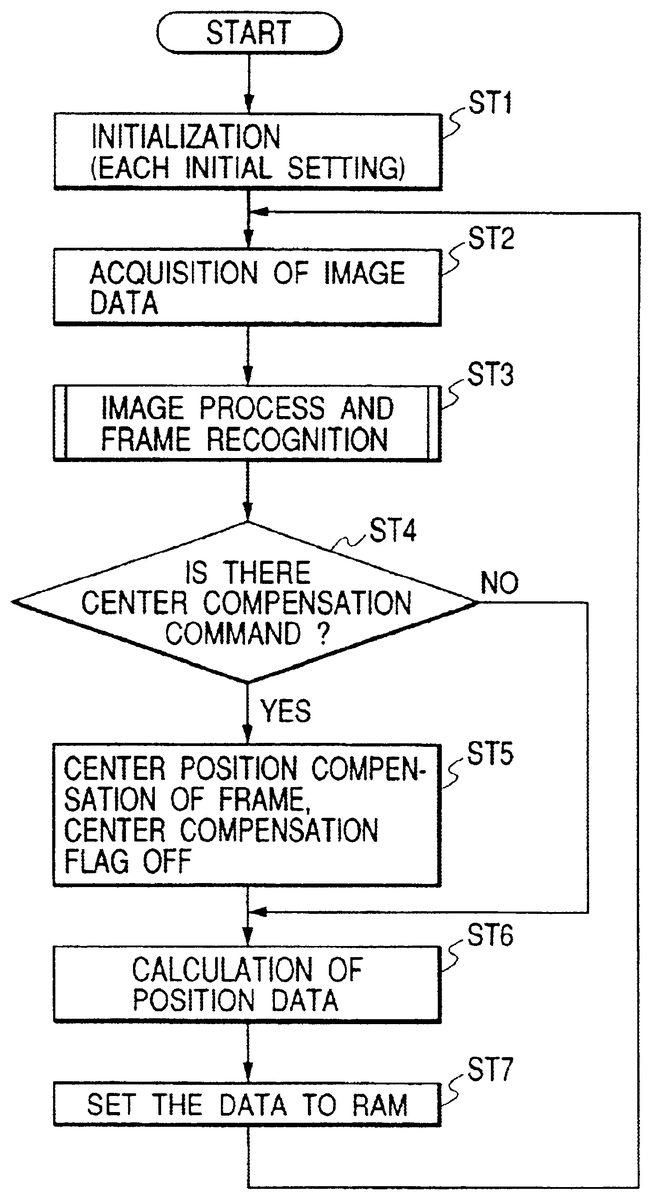
As illustrated inFIG. 3, in the step1(hereinafter, referred to as ST1), when the power of controller1is turned ON or when the controller1is connected to the game machine body20and the power source is supplied from the body side, various necessary initial settings are performed through the reading of the programs for starting and recognition from ROM6. Therefore, the artificial retina LSI4can recognize the images. Subsequently, before starting of the game, a player performs the setting for recognition of reference image.
In the above initial settings, the image data of display area11and frame12of the display unit10are stored in the RAM7with the artificial retina chip3in step ST2. In this case, as explained above, after the image of display area11is displayed in the brightness different from that of the image of frame12, the trigger2is pulled to extract the image data.
In the step ST3, as illustrated inFIG. 4, the image process is performed so that the boundary between the display area11and frame12is emphasized for the image data extracted in the step ST10, and moreover difference in the brightness between the display area11and frame12becomes more distinctive. Upon completion of image process, the processing step moves to the step ST1to determine whether the frame12has an adequate size and can be automatically recognized without departing from the recognizable range or not. In the step ST11, if the frame12is not in the recognizable condition (NG) the out-of-frame flag indicating that the frame12is not in the recognizable range is turned ON and the processing step goes to the processes of step ST4and subsequent steps. Moreover, when the frame is in the recognizable condition (YES) in the step ST11, the processing step moves to the step ST12to perform the image process for twisting and distortion in order to detect the coordinate position data of the frame12. When the image processing and position detection are completed, the out-of-frame flag indicating that the frame12is outside the recognizable range is turned OFF and the processing step goes to the processes of the step ST4and subsequent steps.
In the step ST4, whether the signal to compensate the center position is generated or not is detected. Namely, the image data is not always extracted at the center of the frame12when the trigger2is pulled and the image data is sometimes extracted at the position deviated from the center. Therefore, when the compensation signal to compensate the center is outputted in the step ST4(YES), the processing step moves to the step ST5to compensate the center position of the frame12.
When the center compensation signal is outputted in the step ST4(YES) , the processing step moves to the step ST20indicating the communication process of FIG.5and the flag indicating that the center position at the predetermined position on the data format is turned ON.
In the case where the frame12is recognized as explained above, the artificial retina chip3is recognized in various patterns depending on the direction and inclination of the controller1. Therefore, when the compensation of center position of the frame12is completed in the step ST5, the flag for compensating the center position is turned OFF.
In the step ST6, the coordinate position data of the frame12is calculated. Moreover, after moving to the step ST7, the coordinate position data is stored in the RAM7and this coordinate position data is used in the subsequent processes as the reference image.
Moreover, in the designated position detection process during the game in place of the setting to store the reference image before the start of the game, the processes of the steps ST2to ST7are repeated so long as the power source is not turned OFF or the display unit is not switched to the other display unit.
Namely, the processes similar to that explained above are executed in the steps ST2and ST3and thereafter the processing step moves to the step ST4. In the step ST4, whether the command to compensate the center position is outputted or not is determined, but the processing step goes to the step ST6because it is not the setting to recognize the reference image. In this step ST6, the coordinate position data of the image recognized after the movement is compared with the coordinate position data of the reference image in CPU5and thereby the amount of movement (amount of change) is calculated. After moving to the step ST7, the calculated value is stored in the RAM7. When it is recognized that the calculated value is matched with or included to the coordinate position data displaying the target of the display unit10, the image explained above is reflected on the image displayed when the target is shot.
Here, since the center position compensation command is not outputted (NO) in the step ST4as illustrated inFIG. 5, the processing step moves to the step ST21. In the step ST21, whether the data transmission command to transmit the recognized image data is outputted or not is determined. When the data transmission command is not outputted (NO), the communication process is completed and the processes of the step ST6and the subsequent steps are executed. Moreover, when the data transmission command is received (YES) in the step ST21, the predetermined image process explained above is processed in the step ST22and thereby the image data of the frame12obtained from frame recognition is transmitted and thereby the processes of the step ST6and subsequent steps are also executed.
As explained above, the position on the display area11designated with the controller1can be recognized by calculating displacement between the center position of the display area11obtained by recognizing the frame12surrounding the display area11in the display unit10and the center position of the frame12recognized after the movement.
FIG. 6is an explanatory diagram indicating the other designated position detector with the gun controller for the game machine of the present invention.
The detector illustrated inFIG. 6does not recognize a frame12of the display unit10such as the liquid crystal display as the detection object but uses the identification member30of the desired shape installed or fixed in the external side of the frame12as the detection object.
This identification member30is recognized with the controller1at the time of initial setting before start of the game. The number of identification member30is not limited to only one and it is also possible that two or more identification members are provided and identified. In this case, the detection object may be identified by recognizing the shape of the identification member30or it is also possible that a self-light-emitting radiating member or reflecting member is used as the identification member and the identification member30is identified as the detection object from the difference of brightness between the identification member30and peripheral part.
The present invention explained above can effectively used as the gun controller for the game machine and moreover can detect the designated position even in any type of display unit using different display means that is not limited to that realizing the display of image using the scanning lines, for example, the display unit in which images are displayed without use of the scanning lines and the display unit using a liquid crystal panel, projector or that using different timings of the scanning lines.
Claims
- A designated position detector comprising: a display unit having a display area;a detection object fixed and located outside the display area;and an operation member to execute input operations to the display area via space, wherein the operation member is provided with: an image recognizing mechanism to recognize images;and a control unit to define the detection object recognized with the image recognizing mechanism at a time of initial setting as a reference image, detecting a relative positional displacement between an image of the detection object recognized with the image recognizing mechanism when the operation member is moved and the reference image, and thereby obtaining a position data on the display area designated with the operation member based on such displacement, and the detection object is a frame surrounding the display area in the display unit.
- A designated position detector according to claim 1 , wherein the frame is recognized as the detection object by detecting a difference in the brightness of the image of the display area recognized with the image recognizing mechanism and the image of the frame.
- A designated position detector according to claim 1 , wherein the detection object is provided in a single position outside the display area and the detection object is identified by recognizing difference in a brightness between the detection object and a peripheral part thereof with the image recognition mechanism.
- A designated position detector according to claim 1 , wherein the detection object is at least one object provided in a position outside the display area and the at least one object is identified by recognizing a difference in a brightness between the at least one object and a peripheral part thereof with the image recognition mechanism.
- A designated position detector according to claim 1 , wherein the detection object is at least one object fixed in a position outside the display area and the at least one object is identified by recognizing a difference in a brightness between the at least one object and a peripheral part thereof with the image recognition mechanism.
- A designated position detector comprising: a display unit having a display area;a detection object fixed and located outside the display area;and an operation member to execute input operations to the display area via space, wherein the operation member is provided with: a image recognizing mechanism to recognize images;and a control unit to define the detection object recognized with the image recognizing mechanism at a time of initial setting as a reference image, detecting a relative positional displacement between an image of the detection object recognized with the image recognizing mechanism when the operation member is moved and the reference image, and thereby obtaining a position data on the display area designated with the operation member based on such displacement, and the detection object is provided in a single position outside the display area and the detection object is identified by recognizing a shape of the detection object with the image recognizing mechanism.
- A controller for a game machine comprising: a designated position detector that includes: a display unit having a display area;a detection object fixed and located outside the display area;and an operation member to execute input operations to the display area via space, the operation member provided with: an image recognizing mechanism to recognize images and a control unit to define the detection object recognized with the image recognizing mechanism at a time of initial setting as a reference image, detecting a relative positional displacement between an image of the detection object recognized with the image recognizing mechanism when the operation member is moved and the reference image, and thereby obtaining a position data on the display area designated with the operation member based on such displacement, wherein the detection object is a frame surrounding the display area in the display unit, and game contents are displayed on the display area, the operation member is a controller and positions for the game contents displayed on the display area are designated by moving the controller while the controller is directed toward the display area.
- A controller for the game machine according to claim 7 , wherein the detection object is a frame surrounding the display area in the display unit.
- A controller for the game machine according to claim 8 , wherein, in the designated position detector, the frame is recognized as the detection object by detecting difference in a brightness between an image of the display area recognized with the image recognizing mechanism and the image of the frame.
- A controller for the game machine according to claim 7 , wherein, in the designated position detector, the detection object is provided in single position outside the display area and the detection object is identified by recognizing a shape of the detection object.
- A controller for the game machine according to claim 7 , wherein, in the designated position detector, the detection object is provided in a single position outside the display area and the detection object is identified by recognizing a difference in a brightness between the detection object and a periphery thereof with the image recognizing mechanism.
- A controller for the game machine according to claim 7 , wherein, in the designated position detector, the detection object is fixed in single position outside the display area and the detection object is identified by recognizing a shape of the detection object.
- A controller for the game machine according to claim 7 , wherein, in the designated position detector, the detection object is at least one object provided in a position outside the display area and the object is identified by recognizing a shape of the object.
- A controller for the game machine according to claim 7 , wherein, in the designated position detector, the detection object is at least one object fixed in a position outside the display area and the object is identified by recognizing a shape of the object.
- A controller for the game machine according to claim 7 , wherein, in the designated position detector, the detection object is fixed in a single position outside the display area and the detection object is identified by recognizing a difference in a brightness between the detection object and a periphery thereof with the image recognizing mechanism.
- A controller for the game machine according to claim 7 , wherein, in the designated position detector, the detection object is at least one object provided in a position outside the display area and the object is identified by recognizing a difference in a brightness between the object and a periphery thereof with the image recognizing mechanism.
- A controller for the game machine according to claim 7 , wherein, in the designated position detector, the detection object is at least one object fixed in a position outside the display area and the object is identified by recognizing a difference in a brightness between the object and a periphery thereof with the image recognizing mechanism.
- A designated position detector comprising: a display unit having a display area;a detection object fixed and located outside the display area;and an operation member to execute input operations to the display area via space, wherein the operation member is provided with: an image recognizing mechanism to recognize images;and a control unit to define the detection object recognized with the image recognizing mechanism at a time of initial selling as a reference image, detecting a relative positional displacement between an image of the detection object recognized with the image recognizing mechanism when the operation member is moved and the reference image, and thereby obtaining a position data on the display area designated with the operation member based on such displacement, and the detection object is fixed in single position outside the display area and the detection object is identified by recognizing a shape of the detection object with the image recognizing mechanism.
- A designated position detector comprising: a display unit having a display area;a detection object fixed and located outside the display area;and an operation member to execute input operations to the display area via space, wherein the operation member is provided with: an image recognizing mechanism to recognize images;and a control unit to define the detection object recognized with the image recognizing mechanism at a time of initial setting as a reference image, detecting a relative positional displacement between an image of the detection object recognized with the image recognizing mechanism when the operation member is moved and the reference image, and thereby obtaining a position data on the display area designated with the operation member based on such displacement, and the detection object is at least one object provided in a position outside the display area and the at least one object is identified by recognizing a shape of the at least one object with the image recognizing mechanism.
- A designated position detector comprising: a display unit having a display area;a detection object fixed and located outside the display area;and an operation member to execute input operations to the display area via space, wherein the operation member is provided with: an image recognizing mechanism to recognize images;and a control unit to define the detection object recognized with the image recognizing mechanism at a time of initial setting as a reference image, detecting a relative positional displacement between an image of the detection object recognized with the image recognizing mechanism when the operation member is moved and the reference image, and thereby obtaining a position data on the display area designated with the operation member based on such displacement, and the detection object is at least one object fixed in a position outside the display area and the detection objects are identified by recognizing a shape of the at least one object with the image recognizing mechanism.
Disclaimer: Data collected from the USPTO and may be malformed, incomplete, and/or otherwise inaccurate.