U.S. Pat. No. 6,933,861
KEY-OPERATING DEVICE FOR A HAND-HELD VIDEO GAME APPARATUS
AssigneeAlfadata Computer Corp.
Issue DateNovember 29, 2002
Illustrative Figure
Abstract
A key-operating device includes a shell confining a chamber therein and connected to a video game apparatus with depressible keys, a lever pivotally mounted in the chamber and having protrusions projecting toward the keys, a wheel surrounding and connected to the shell and rotatable relative to the shell, and an actuating member projecting from the wheel and engageable with the lever in such a manner that rotation of the wheel results in engagement between the actuating member and the lever so as to permit fulcrum movement of the lever and pressing of the keys by the protrusions.
Description
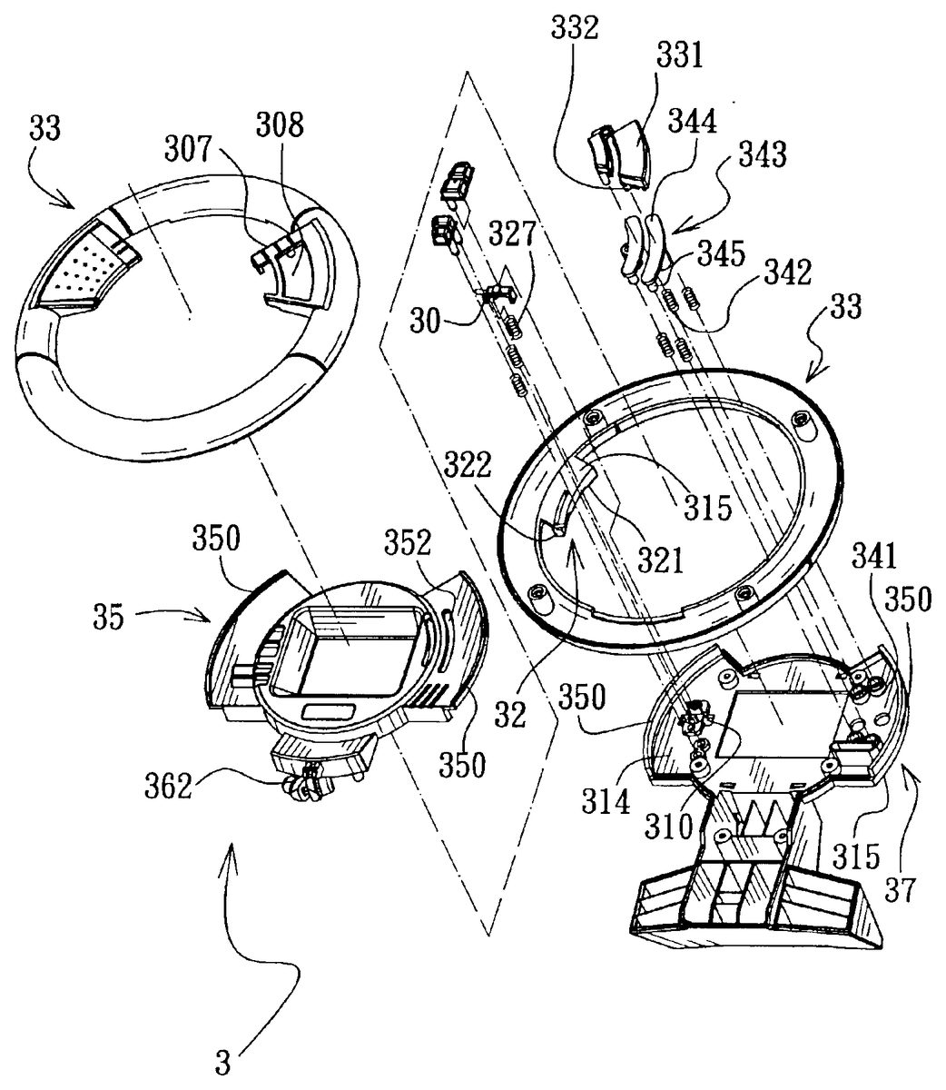
DETAILED DESCRIPTION OF THE PREFERRED EMBODIMENT FIGS. 2to7illustrate a preferred embodiment of a key-operating device3of this invention with the conventional hand-held video game apparatus4ofFIG. 1mounted thereon. The key-operating device3includes: a shell having opposite front and rear shell halves35,37that are coupled together to define a mounting chamber38therebetween (see FIG.5), the rear shell half37having an inner rear face314confining a rear side of the mounting chamber38, and an outer rear face315opposite to the inner rear face314, the shell being formed with a central opening39extending through the front and rear shell halves35,37, the outer rear face315being connected to the hand-held video game apparatus4in such a manner that the display screen40can be viewed through the central opening39, the outer rear face315being formed with a key-receiving opening310(seeFIGS. 3 and 6) that is disposed adjacent to the central opening39and that receives the left and right keys411,412therein, the front and rear shell halves35,37including a pair of opposing wings350extending oppositely in a direction away from the central opening39; a spring-biased lever30mounted pivotally on the inner rear face314through a pivot311and having two opposite ends with key-pressing protrusions328,329that project rearwardly and respectively toward the left and right keys411,412; an operating wheel33having an annular inner face300that surrounds the shell, and formed with a pair of circumferentially extending retaining slots301(seeFIG. 6) that extend inwardly of the operating wheel33from the annular inner face300and that receive respectively the wings350so as to permit rotation of the operating wheel33relative to the shell between first and second angular positions (see FIGS.8and11); and an actuating member32connected to and projecting from the annular inner face300of the operating wheel33toward the lever30and engageable with the lever30in such a manner that rotation of the operating wheel33to the first angular position results in fulcrum movement of the lever30in a first direction, which, in turn, results in pressing of the left key411by the key-pressing protrusion328(see ...
DETAILED DESCRIPTION OF THE PREFERRED EMBODIMENT
FIGS. 2to7illustrate a preferred embodiment of a key-operating device3of this invention with the conventional hand-held video game apparatus4ofFIG. 1mounted thereon.
The key-operating device3includes: a shell having opposite front and rear shell halves35,37that are coupled together to define a mounting chamber38therebetween (see FIG.5), the rear shell half37having an inner rear face314confining a rear side of the mounting chamber38, and an outer rear face315opposite to the inner rear face314, the shell being formed with a central opening39extending through the front and rear shell halves35,37, the outer rear face315being connected to the hand-held video game apparatus4in such a manner that the display screen40can be viewed through the central opening39, the outer rear face315being formed with a key-receiving opening310(seeFIGS. 3 and 6) that is disposed adjacent to the central opening39and that receives the left and right keys411,412therein, the front and rear shell halves35,37including a pair of opposing wings350extending oppositely in a direction away from the central opening39; a spring-biased lever30mounted pivotally on the inner rear face314through a pivot311and having two opposite ends with key-pressing protrusions328,329that project rearwardly and respectively toward the left and right keys411,412; an operating wheel33having an annular inner face300that surrounds the shell, and formed with a pair of circumferentially extending retaining slots301(seeFIG. 6) that extend inwardly of the operating wheel33from the annular inner face300and that receive respectively the wings350so as to permit rotation of the operating wheel33relative to the shell between first and second angular positions (see FIGS.8and11); and an actuating member32connected to and projecting from the annular inner face300of the operating wheel33toward the lever30and engageable with the lever30in such a manner that rotation of the operating wheel33to the first angular position results in fulcrum movement of the lever30in a first direction, which, in turn, results in pressing of the left key411by the key-pressing protrusion328(see FIG.9), and that rotation of the operating wheel33to the second angular position results in fulcrum movement of the lever30in a second direction opposite to the first direction, which, in turn, results in pressing of the right key412by the key-pressing protrusion329(see FIG.12). A pair of retaining protrusions317(only one of the retaining protrusions317is shown inFIG. 2) project from the outer rear face315of the rear shell half37. Each of the retaining protrusions317has a hook end318for holding firmly the hand-held video game apparatus4. A stand50is provided on the key-operating device3, and extends from the rear shell half37.
The actuating member32includes an extension plate315connected to and projecting from the annular inner face300of the operating wheel33toward the lever30, front and rear driving protrusions321,322that project from the extension plate315, that cooperatively define a gap320therebetween, and that respectively have rear and front inclined faces323,324facing oppositely (see FIG.4), and a driven protrusion326that projects from an adjacent one of the ends of the lever30into the gap320. The rear and front inclined faces323,324face toward the driven protrusion326, and extend in a circumferential direction relative to the operating wheel33(see FIG.7). The rear and front inclined faces323,324are inclined oppositely in the circumferential direction in such a manner that the rear inclined face323presses the driven protrusion326in a rearward direction (seeFIG. 10) upon rotation of the operating wheel33to the first angular position, thereby permitting fulcrum movement of the lever30in the first direction, and that the front inclined face324presses the driven protrusion326in a frontward direction (seeFIG. 13) upon rotation of the operating wheel33to the second angular position, thereby permitting fulcrum movement of the lever30in the second direction.
The spring-biased lever30includes an urging member327sleeved on the key-pressing protrusion328and abutting against a respective one of the ends of the lever30so as to permit returning of the lever30to a non-actuated position (see FIG.6), in which, the key-pressing protrusions328,329disengage simultaneously and respectively from the left and right keys411,412.
Referring toFIGS. 14 and 15, the operating wheel33confines an annular chamber306therein, and is further formed with a pair of radially extending spring-abutting ribs361in the annular chamber306. The shell further includes a spring-pushing arm362projecting therefrom into the annular chamber306between the spring-abutting ribs361. The key-operating device3further includes a pair of returning coil springs363disposed respectively between the spring-pushing arm362and one of the spring-abutting ribs361and between the spring-pushing arm362and the other one of the spring-abutting ribs361and abutting against the spring-pushing arm362and the spring-abutting ribs361so as to permit returning of the operating wheel33to a middle position (seeFIG. 5) between the first and second angular positions when the operating wheel33is positioned at one of the first and second angular positions. A pair of retaining members308project oppositely from two opposite sides of the spring-pushing arm362. The returning coil springs363have retaining ends sleeved on and abutting against the retaining members308, respectively.
Referring now toFIGS. 3 and 5, the front shell half35is formed with an arcuate elongated opening352that has two opposite ends. The rear shell half37is formed with a through-hole341that is registered with one of the ends of the elongated opening352and that is registered with the function key45. The operating wheel33further includes a mounting tab307projecting from the annular inner face300toward the central opening39and formed with a button-mounting hole308that is registered with and that is disposed frontwardly of the elongated opening352. The key-operating device3further includes a button331that is mounted on the mounting tab307, that projects movably through the button-mounting hole308, and that has a first pushing protrusion332which projects rearwardly through the elongated opening352and which is movable together with the button331along the length of the elongated opening352upon rotation of the operating wheel33. The key-operating device3further includes a spring-biased pressing member343that is mounted movably in the mounting chamber38and that has an elongated plate344which is disposed rearwardly and which covers the elongated opening352, and a second pushing protrusion345which projects rearwardly from the elongated plate344and through the through-hole341in the rear shell half37. The button331is depressible rearwardly so as to push the elongated plate344through the first pushing protrusion332, which, in turn, results in pressing of the function key445by the second pushing protrusion345. A returning coil spring342is sleeved on the second pushing protrusion345so as to permit returning of the button331and the pressing member343from a depressed state to a non-depressed state.
In operation, when playing a video game, such as a car racing game, with the use of the hand-held video game apparatus4, left and right movements of the car in the video game can be controlled by rotation of the operating wheel33. As such, the operating wheel33can provide a better simulation of driving a real car, thereby eliminating the aforesaid drawback associated with the prior art.
With the invention thus explained, it is apparent that various modifications and variations can be made without departing from the spirit of the present invention. It is therefore intended that the invention be limited only as recited in the appended claims.
Claims
- A key-operating device for a hand-held video game apparatus which has a display screen, depressible left and right keys, and a depressible function key, said key-operating device comprising: a shell including opposite front and rear shell halves that are coupled together to define a mounting chamber therebetween, said rear shell half having an inner rear face confining a rear side of said mounting chamber, and an outer rear face opposite to said inner rear face, said shell being formed with a central opening extending through said front and rear shell halves, said outer rear face being adapted to be connected to the hand-held video game apparatus in such a manner that the display screen can be viewed through said central opening, said outer rear face being formed with a key-receiving opening that is disposed adjacent to said central opening and that is adapted to receive the left and right keys therein, said front and rear shell halves including a pair of opposing wings extending oppositely in a direction away from said central opening;a spring-biased lever mounted pivotally on said inner rear face and having two opposite ends with key-pressing protrusions that are adapted to project rearwardly and respectively toward the left and right keys;an operating wheel having an annular inner face that surrounds said shell, and formed with a pair of circumferentially extending retaining slots that extend inwardly of said operating wheel from said annular inner face and that receive respectively said wings so as to permit rotation of said operating wheel relative to said shell between first and second angular positions;and an actuating member connected to and projecting from said annular inner face of said operating wheel toward said lever and engageable with said lever in such a manner that rotation of said operating wheel to said first angular position results in fulcrum movement of said lever in a first direction, which, in turn, results in pressing of one of the left and right keys by a respective one of said key-pressing protrusions, and that rotation of said operating wheel to said second angular position results in fulcrum movement of said lever in a second direction opposite to said first direction, which, in turn, results in pressing of the other one of the left and right keys by the other one of said key-pressing protrusions.
- The key-operating device of claim 1 , wherein said actuating member includes front and rear driving protrusions that cooperatively define a gap therebetween, and that respectively have rear and front inclined faces facing oppositely, and a driven protrusion that projects from an adjacent one of said ends of said lever into said gap, said front and rear inclined faces facing toward said driven protrusion and extending in a circumferential direction relative to said operating wheel, said front and rear inclined faces being inclined oppositely in said circumferential direction in such a manner that said rear inclined face presses said driven protrusion in a rearward direction upon rotation of said operating wheel to said first angular position, thereby permitting fulcrum movement of said lever in said first direction, and that said front inclined face presses said driven protrusion in a frontward direction upon rotation of said operating wheel to said second angular position, thereby permitting fulcrum movement of said lever in said second direction.
- The key-operating device of claim 1 , wherein said spring-biased lever includes an urging member sleeved on one of said key-pressing protrusions and abutting against a respective one of said ends of said lever so as to permit returning of said lever to a non-actuated position, in which, said key-pressing protrusions are adapted to disengage simultaneously and respectively from the left and right keys.
- The key-operating device of claim 1 , wherein said operating wheel confines an annular chamber therein, and is further formed with a pair of radially extending spring-abutting ribs in said annular chamber, said shell further including a spring-pushing arm projecting therefrom into said annular chamber between said spring-abutting ribs, said key-operating device further comprising a pair of coil springs disposed respectively between said spring-pushing arm and one of said spring-abutting ribs and between said spring-pushing arm and the other one of said spring-abutting ribs and abutting against said spring-pushing arm and said spring-abutting ribs so as to permit returning of said operating wheel to a middle position between said first and second angular positions when said operating wheel is positioned at one of said first and second angular positions.
- The key-operating device of claim 1 , wherein said front shell half is formed with an arcuate elongated opening that has two opposite ends, said rear shell half being formed with a through-hole that is registered with one of said ends of said elongated opening and that is adapted to be registered with the function key, said operating wheel further including a mounting tab projecting from said annular inner face toward said central opening and formed with a button-mounting hole that is registered with and that is disposed frontwardly of said elongated opening, said key-operating device further comprising a button that is mounted on said mounting tab, that projects movably through said button-mounting hole, and that has a first pushing protrusion which projects rearwardly into and through said elongated opening and which is movable together with said button along the length of said elongated opening upon rotation of said operating wheel, said key-operating device further comprising a spring-biased pressing member that is mounted movably in said mounting chamber and that has an elongated plate which is disposed rearwardly and which covers said elongated opening, and a second pushing protrusion which projects rearwardly from said elongated plate and through said through-hole in said rear shell half, said button being depressible rearwardly so as to push said elongated plate through said first pushing protrusion, which, in turn, results in pressing of the function key by said second pushing protrusion.
Disclaimer: Data collected from the USPTO and may be malformed, incomplete, and/or otherwise inaccurate.