U.S. Pat. No. 6,932,341
VIDEO GAME SYSTEM AUXILIARY COVER SYSTEM
Issue DateFebruary 23, 2004
Illustrative Figure
Abstract
A system by which interchangeable covers are provided for video game consoles and controllers to provide a wide variety of appearances is disclosed. It is envisioned that the system would be customized to work with popular video game consoles. To change the appearance of an existing console, the user would simply snap the new cover over or on the existing manufacturer's cover. The cover would be specifically designed to accommodate all access panels, buttons, cooling vents, connection ports and the like. The new covers would be specifically designed to go with a specific game or be of a more generally styled theme. The game controller covers are two halves that snap around the controller yet expose all control buttons and surfaces. It is also envisioned that an LED lighting system could be embedded in the controller case cover to add an interesting artistic touch by way of case illumination.
Description
DESCRIPTIVE KEY 10video game system auxiliary cover system15video game console20first snap clips25connector openings30connectors35switch openings40switches45media tray opening50media tray55power cable60monitor cable65vent openings70first graphic displays75furnished graphic images80user supplied images85blank space area90fiber optic strands95display points100power pigtail cable105pass through power connector110light emitting diode (LED)115game controller cover system120game controller125game controller top half130game controller bottom half135joysticks140pushbuttons145paddle switches150openings155second snap clips160receiving clips165second graphic displays DESCRIPTION OF THE PREFERRED EMBODIMENTS The best mode for carrying out the invention is presented in terms of its preferred embodiment, herein depicted within theFIGS. 1 through 4. 1. Detailed Description of the Figures Referring now toFIG. 1, an overall pictorial representation of the video game system auxiliary cover system10shown in an utilized state upon a video game console15is depicted, according the preferred embodiment of the present invention. The video game system auxiliary cover system10is an overall cover which encapsulates the video game console15on multiple sides. The video game console15is depicted as a generic game console for the purposes of illustration. It is envisioned that specifically designed models of the video game system auxiliary cover system10would be produced for all past, current and future home video gaming consoles, including systems10for X-Box®, PlayStation® consoles, Ninetendo Gamecube® and others. The dimensions and associated tolerances are such that the video game system auxiliary cover system10would be held in place on the video game console15via friction fit along with the aid of first snap clips20, which grip the bottom corners and side surface of the video game console15. Two of four first snap clips20are visible in this view for purposes of clarity. The number and placement of the first snap clips20would vary dependent on the shape of the video game console15and as such is not intended to be a limiting factor of the present invention. A pair of connector openings25are provided on the front of the video game system ...
DESCRIPTIVE KEY
10video game system auxiliary cover system15video game console20first snap clips25connector openings30connectors35switch openings40switches45media tray opening50media tray55power cable60monitor cable65vent openings70first graphic displays75furnished graphic images80user supplied images85blank space area90fiber optic strands95display points100power pigtail cable105pass through power connector110light emitting diode (LED)115game controller cover system120game controller125game controller top half130game controller bottom half135joysticks140pushbuttons145paddle switches150openings155second snap clips160receiving clips165second graphic displays
DESCRIPTION OF THE PREFERRED EMBODIMENTS
The best mode for carrying out the invention is presented in terms of its preferred embodiment, herein depicted within theFIGS. 1 through 4.
1. Detailed Description of the Figures
Referring now toFIG. 1, an overall pictorial representation of the video game system auxiliary cover system10shown in an utilized state upon a video game console15is depicted, according the preferred embodiment of the present invention. The video game system auxiliary cover system10is an overall cover which encapsulates the video game console15on multiple sides. The video game console15is depicted as a generic game console for the purposes of illustration. It is envisioned that specifically designed models of the video game system auxiliary cover system10would be produced for all past, current and future home video gaming consoles, including systems10for X-Box®, PlayStation® consoles, Ninetendo Gamecube® and others. The dimensions and associated tolerances are such that the video game system auxiliary cover system10would be held in place on the video game console15via friction fit along with the aid of first snap clips20, which grip the bottom corners and side surface of the video game console15. Two of four first snap clips20are visible in this view for purposes of clarity. The number and placement of the first snap clips20would vary dependent on the shape of the video game console15and as such is not intended to be a limiting factor of the present invention. A pair of connector openings25are provided on the front of the video game system auxiliary cover system10to allow access to connectors30, such as those provided for game controllers. In a similar manner, a pair of switch openings35provides access to a set of switches40, such as those provided for power or ejecting of the gaming media. Finally, also located on the front of the video game system auxiliary cover system10, is a media tray opening45which allows access to a media tray50, such as those for a compact disc (CD), digital versatile disc (DVD) or other proprietary media. In a similar manner, although not visible in this view, are openings for a power cable55which provides electrical power into the video game console15and a monitor cable60which provides video and audio signals to a monitor system. A set of multiple vent openings65are provided on the side of the video game system auxiliary cover system10or at any location vents are provided by the manufacturer of the video game console15. In this manner, it is ensured that any heat producing components located inside of the video game console15can be allowed access to outside ambient air. First graphic displays70are provided on the top surface of the video game system auxiliary cover system10, in this case a graphic representation of flames is provided. The first graphic displays70can be virtually anything and is envisioned to be related to specific games played on the video game console15, sport teams, children's themes, adult themes, fantasy themes, and the like. Additional furnished graphic images75such as holographic images, photographic images and the like may also be furnished. Finally, user supplied images80such as stickers and the like can be added to blank space area85furnished on the top of the video game system auxiliary cover system10by the final user.
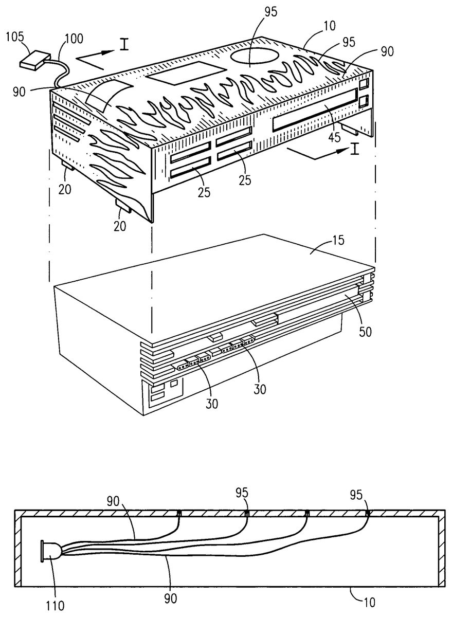
Referring next toFIG. 2, an exploded isometric view of the video game system auxiliary cover system10and the video game console15is disclosed. This FIG. more clearly depicts the attachment method between the video game system auxiliary cover system10and the video game console15and the simple method of installation. No tools are required to remove or install the video game system auxiliary cover system10. A simple friction fit is all that is necessary. Proper alignment of the connector openings25with the connectors30and the media tray opening45with the media tray50along with all other openings is assured dependent on the make and model of the video game console15. It is envisioned that in addition for providing customization of the video game console15, the video game system auxiliary cover system10can also be used to provide physical protection as well against dirt, dust, scratches and the like. Additionally, the user can apply stickers and other graphic images to the video game system auxiliary cover system10in lieu of the video game console15, thus not reducing the value and subsequent resale value of the video game console15. Finally, should an existing video game console15be damaged, scratched or cracked, the user can install the video game system auxiliary cover system10to provide a like new appearance. This FIG. also provides a different type of first graphic displays70, such as fireworks. It is also envisioned that this type of first graphic displays70would utilize integral fiber optic strands90to produce display points95of light. The light would be produced by light-emitting diodes (LED's) as will be described in greater detail herein below. Electrical power for the LED's will be provided by a power pigtail cable100which would connect to the power input point of the power cable55(as shown inFIG. 1). In such a manner, the top surface of the video game system auxiliary cover system10will light up in a dark room with a multi-colored display, thus making playing video games at night or in low-light conditions an exciting event.
Referring now toFIG. 3, a sectional view of the video game system auxiliary cover system10as seen along a line I—I shown inFIG. 2is disclosed. A light emitting diode (LED)110is embedded in the top surface of the video game system auxiliary cover system10(and/or the game controller cover115) The long life nature of the video game system auxiliary cover system10, coupled with their low heat dissipation and small size allow them to be sealed within the plastic structure of the video game system auxiliary cover system10without need for replacement. A set of multiple strands from the fiber optic strands90is aligned with the video game system auxiliary cover system10and similarly embedded within the top surface of the video game system auxiliary cover system10. The fiber optic strands90are then routed outward and spread out where they turn upwards and penetrate the top surface of the video game system auxiliary cover system10. It is envisioned that multiple light emitting diode (LED)110of different colors such as red, green, white, yellow, and blue could be used with overlapping and intertwined fiber optic strands90to produce words, pictures and the like.
Referring finally toFIG. 4, an exploded isometric view of a game controller cover system115as used with a game controller120is disclosed. The game controller cover system115consists of a game controller top half125and a game controller bottom half130as shown. The game controller120is intended to be a generic representation of any one of the multitude of manufacturers as aforementioned described. The game controller120is provided with a multitude of joysticks135, pushbuttons140, and paddle switches145as commonly expected. The game controller top half125is then provided with a multitude of openings150that match abovementioned protrusions. The game controller top half125is provided with a set of second snap clips155that align with a matching set of receiving clips160on the game controller bottom half130. The game controller bottom half130provides a basically concave form to encompass the bottom of the game controller120. A set of second graphic displays165on the game controller top half125would match the first graphic displays70on the video game system auxiliary cover system10(as shown inFIG. 1andFIG. 2). The game controller top half125and the game controller bottom half130can be applied and removed by hand without the use of tools or excessive force. In a manner similar to the video game system auxiliary cover system10(as shown inFIG. 1), the game controller cover system115provides physical protection for the game controller120or can cover surface or cosmetic damage that may be existing on the game controller120. It is further envisioned that the game controller cover system115includes a plurality of LEDs or a plurality of fiber optic strands are embedded in the system115to provide additional aesthetic lighting to the system115, either standing apart from the LEDs or fiber optic strands of the cover system10or as a compliment to the cover system10, thus providing a lighted visual effect. The LED or fiber optic arrangement or configuration may be similar to the that disclosed in relation to the cover system10, or may include an arrangement different to accommodate the remoteness of the controller from the console itself.
It is envisioned that other styles and configurations of the present invention can be easily incorporated into the teachings of the present invention, and only one particular configuration shall be shown and described for purposes of clarity and disclosure and not by way of limitation of scope.
2. Operation of the Preferred Embodiment
The preferred embodiment of the present invention can be utilized by the common user in a simple and effortless manner with little or no training. After purchase or procurement of the video game system auxiliary cover system10it must be applied to the video game console15and corresponding game controller120. To begin the installation process, the user would unplug all power cable55, all monitor cable60, all controller cables, and any other device which may protrude from the video game console15. Next, the video game system auxiliary cover system10is simply slid over the video game console15and attached to the base of the video game console15by use of the first snap clips20. In a similar manner, the game controller top half125and the game controller bottom half130are snapped around the game controller120and secured using the second snap clips155in the receiving clips160. Next, any power cable55, any monitor cable60, any controller cables, and any other device that was aforementioned removed, must be reinstalled. If the video game system auxiliary cover system10should be equipped with a light emitting diode (LED)110and fiber optic strands90, the user would connect the pass through power connector105of the power pigtail cable100to the power cable55before it connects to the video game console15. At this point the video game system auxiliary cover system10is ready for use.
During the actual use of the video game console15equipped with the video game system auxiliary cover system10, nothing is readily different nor is the actual game playing activity modified. However, the additional aesthetic value provided by the video game system auxiliary cover system10coupled with the internal lighting afforded by the fiber optic strands90and the light emitting diode (LED)110, if so equipped, will provide additional entertainment value. If the user wishes to remove the video game system auxiliary cover system10for the purposes of applying a different one, or applying to a new video game console15, or if selling the video game console15, it can be removed easily be snapping it off.
The foregoing descriptions of specific embodiments of the present invention have been presented for purposes of illustration and description. They are not intended to be exhaustive or to limit the invention to the precise forms disclosed, and obviously many modifications and variations are possible in light of the above teaching. The embodiments were chosen and described in order to best explain the principles of the invention and its practical application, to thereby enable others skilled in the art to best utilize the invention and various embodiments with various modifications as are suited to the particular use contemplated. It is intended that the scope of the invention be defined by the claims appended hereto and their equivalents. Therefore, the scope of the invention is to be limited only by the following claims.
Claims
- An auxiliary cover system for a video game console and game controller comprising: a video game console cover placed over said console, wherein said console cover has a plurality of fiber optic strands embedded in a top surface thereof for providing a lighted visual effect.
- The auxiliary cover system of claim 1 , wherein said video game console cover comprises: a top half having a plurality of openings corresponding to joysticks, pushbuttons and paddle switches provided on said game controller;and a bottom half having a form complementary to a bottom half of said game controller;said top half and said bottom half coupled via snap clips.
- The auxiliary cover system of claim 2 , wherein said video game console cover has a display provided on a top surface thereof.
- The auxiliary cover system of claim 1 , wherein said console cover comprises: a pair of connector openings to permit egress of connectors;a pair of switch openings to permit access to switches;and a media tray opening to permit access to a media tray.
- The auxiliary cover system of claim 4 , wherein said console cover further comprises a plurality of openings for cables.
- The auxiliary cover system of claim 5 , wherein said console cover further comprises a plurality of vent openings corresponding to vents on said console, thereby discharging heated air to outside ambient air.
- The auxiliary cover system of claim 1 , wherein said console cover has a first graphic display provided on a top surface thereof.
- The auxiliary cover system of claim 7 , wherein said first graphic display is a member selected from the group consisting of sports themes, children's themes, adult themes and fantasy themes.
- The auxiliary cover system of claim 7 , wherein said console cover further comprises furnished graphic images.
- The auxiliary cover system of claim 7 , wherein said console cover further comprises user supplied images.
Disclaimer: Data collected from the USPTO and may be malformed, incomplete, and/or otherwise inaccurate.