U.S. Pat. No. 6,929,548
APPARATUS AND A METHOD FOR MORE REALISTIC SHOOTING VIDEO GAMES ON COMPUTERS OR SIMILAR DEVICES
Issue DateApril 23, 2002
Illustrative Figure
Abstract
An apparatus, system, and a method for providing more realistic shooting input for shooting video games on computers or similar devices is provided. The apparatus may be comprised of a mock shooting device, such as a gun, having a lighting device containing a plurality of light sources. The apparatus may also include a screen device for displaying visual target objects of a video shooting game, at which a game player can shoot at with the mock shooting device, a video camera that captures video images of the mock shooting device, and a computing device that computes the hit position of the mock shooting device on the screen device based on the captured video images. The determined hit position can then be fed to the video shooting game software run by the computing device which can determine if a visual target object is actually hit or not, and reacts accordingly. The system and method can be extended to a plurality of game players using mock shooting devices with different colored lighting devices so that a plurality of hit positions for different colors may be determined.
Description
DETAILED DESCRIPTION OF THE INVENTION The present invention in one or more embodiments provides a solution that can make shooting video games much more realistic on computers or similar devices, such as the PLAYSTATION (trademarked) from SONY (trademarked), that contain at least one processor, a memory device and/or a storage device, a monitor or a display screen, such as a television set, a low cost video camera, and some input devices, such as a game pad, and/or joysticks. A system, apparatus, and method according to the present invention uses a mock shooting device, such as a mock gun, a mock machine gun, or a mock rocket launcher, with a lighting device. A game player uses the mock shooting device to aim and shoot at one of one or more target objects displayed on a screen by a video shooting game. When the mock shooting device is triggered, a lighting device on or part of the mock shooting device, flashes light. The lighting device includes one or more light sources and is mounted on or built in the mock shooting device. The mock shooting device can be triggered continuously with a predefined time interval when its triggering device is pulled back and not released or the mock shooting device can be triggered just one time with a quick pull back and release. The mock shooting device may also provide audio or visual feedback signals indicating that the device has been triggered. For example, the mock shooting device may play a very short and typical gun shooting sound clip when it is triggered. When it is continuously triggered, the very short and typical gun shooting sound clip will be repeated with a predefined time interval as long as the trigger is pulled back and not released. In addition, because the lighting device ...
DETAILED DESCRIPTION OF THE INVENTION
The present invention in one or more embodiments provides a solution that can make shooting video games much more realistic on computers or similar devices, such as the PLAYSTATION (trademarked) from SONY (trademarked), that contain at least one processor, a memory device and/or a storage device, a monitor or a display screen, such as a television set, a low cost video camera, and some input devices, such as a game pad, and/or joysticks.
A system, apparatus, and method according to the present invention uses a mock shooting device, such as a mock gun, a mock machine gun, or a mock rocket launcher, with a lighting device. A game player uses the mock shooting device to aim and shoot at one of one or more target objects displayed on a screen by a video shooting game. When the mock shooting device is triggered, a lighting device on or part of the mock shooting device, flashes light. The lighting device includes one or more light sources and is mounted on or built in the mock shooting device. The mock shooting device can be triggered continuously with a predefined time interval when its triggering device is pulled back and not released or the mock shooting device can be triggered just one time with a quick pull back and release. The mock shooting device may also provide audio or visual feedback signals indicating that the device has been triggered. For example, the mock shooting device may play a very short and typical gun shooting sound clip when it is triggered. When it is continuously triggered, the very short and typical gun shooting sound clip will be repeated with a predefined time interval as long as the trigger is pulled back and not released. In addition, because the lighting device flashes light when it is triggered, the light may also serve as a visual feedback signal for the shooting.
A system, apparatus, and method according to the present invention uses a commonly available low-cost video camera, such as a web cam, mounted on top of a screen device, such as a computer monitor or a TV set, to capture the video images containing the light from the lighting device. The hit position on the screen at which the mock shooting device aims and shoots, can be determined from the captured video images containing the mock shooting device. The hit position can then be fed to the shooting video game computer software which can determine if a target is actually hit or not. It should be noted that hereinafter the word “hit”, used throughout this application, is meant to be a virtual hit on the screen by a virtual bullet fired by the mock shooting device, instead of an actual hit in a physical sense.
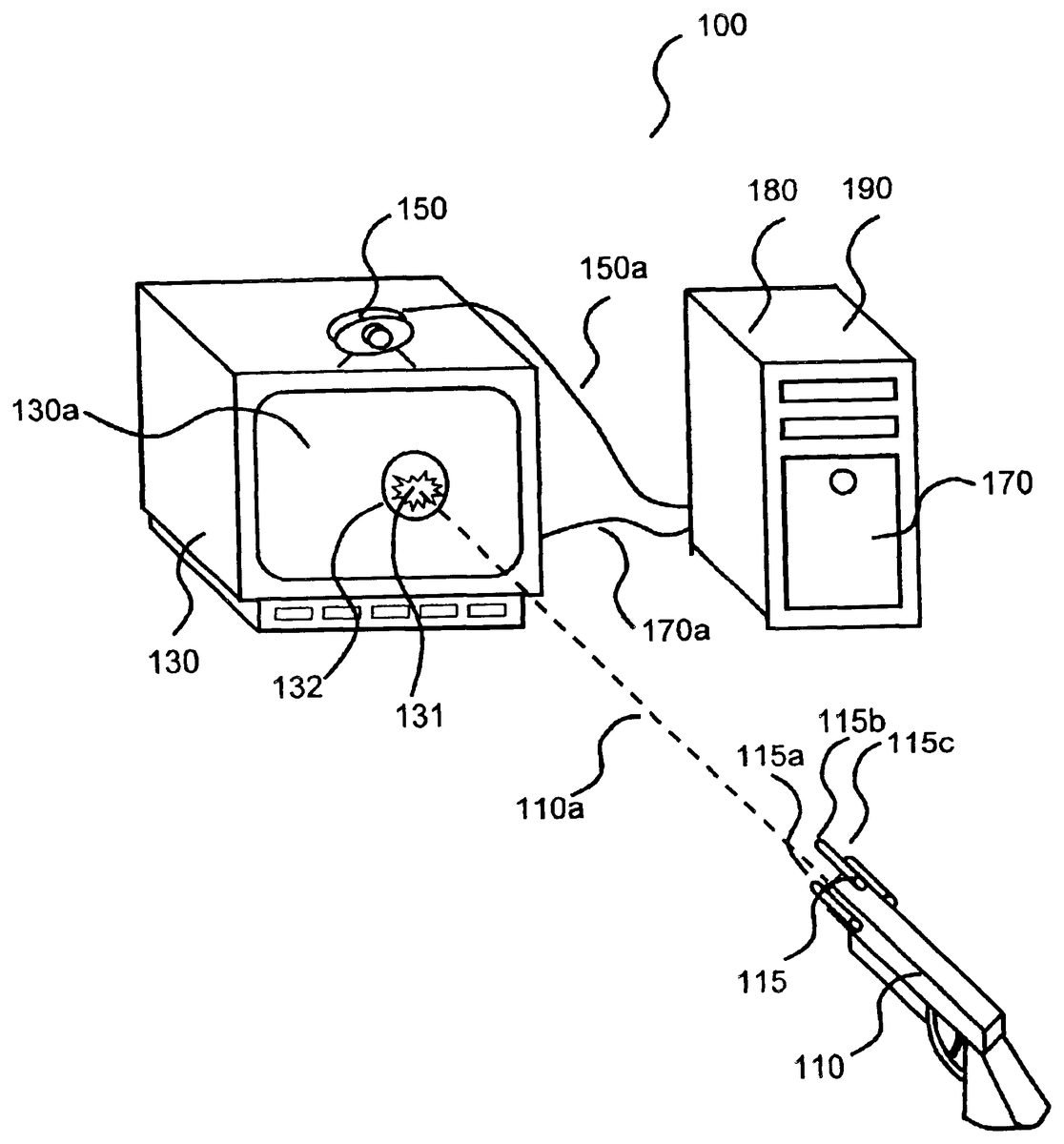
A perspective view of a system, apparatus, and method according to one preferred embodiment of the present invention is shown in FIG.1.FIG. 1shows an apparatus100comprised of a mock shooting device110, a screen device130, a video camera150, and a computing device170. The computing device170may be a personal computer. The screen device130is electrically connected to the computing device170by communications line170a. The video camera150is electrically connected to the computing device170by communications line150a. The communications lines150aand170amay be comprised of wireless connections, hardwired connections, optical connections, software connections, or any other known communication connections.
The mocking shooting device110includes a lighting device115. The lighting device115may be comprised of three lights115a,115b, and115c.The screen device130can display target visual objects to be aimed and shot at. The video camera150may be used to capture video images from the mock shooting device110and the video camera150can be mounted onto the screen device130. The computing device170may be comprised of a hit determination device180, which may be comprised of computer software which is part of and is running on the computing device170. The hit determination device180may determine the hit position, such as hit position131, on the screen device130at which the mock shooting device110was aiming and shooting.
The shooting path (trajectory)110ais the virtual shooting path of a virtual bullet from the mock shooting device110to the screen device130. The light from lights115a,115b, and115cor some other light is usually non-directional so that they can be observed from a large range of directions. For this reason, each of lights115a-cmay be a typical small light bulb or a small LED. The lights115a-cdo not need to be expensive directional lights, such as lasers. The screen device130includes a screen130aon which visual target objects, such as target object132, are displayed. The computing device170is also responsible for running the shooting game190, which may be comprised of computer software, that displays visual target objects to be shot at on the screen130aand reacts accordingly depending on whether a visual target object has been hit or not. With some exceptions, the video shooting game190may be similar to those prior art video shooting games which are typically comprised of computer software and which run on computers. One of the differences of the present invention is how user shooting information is input into the computing device170. The system and method according to the present invention uses a realistic mock shooting device110and a video camera150for inputting user shooting information while conventional prior art games use a keyboard, mouse, game pad or joysticks.
In operation, referring toFIG. 1, a game player starts a video shooting game190stored in a computing device170. The video shooting game190may be initially supplied to the computing device170via compact disc, floppy disc, downloaded from the Internet, or in any other known manner. The shooting game190displays scenes with one or more visual target objects, such as circular target object132, on the screen130avia communications line170a. Typical examples of the communications line170aare common video display cable and the Universal Serial Bus (USB) cable version 1.1 and 2.0 for computer monitors, and composite video, S-video or RGB video cables for television sets. The game player uses the mock shooting device110to aim and shoot at the displayed target objects provided by the video shooting game190on the screen130a.When the game player triggers the mock shooting device110, one or more of the plurality of light sources115a-cof the lighting device115, flashes light. The light sources115a-care each rigidly mounted on or integrated within the mock shooting device110. The video camera150placed on top of the screen device130captures video images from the one or more flashing light sources115a-cof the lighting device115and sends the video images through communications line150ato the computing device170. Typical and common examples of the communications line150aare the Universal Serial Bus (USB) cable version 1.1 and 2.0, or cables made according to the IEEE 1394 standard, such as the FIREWIRE (Trademarked) and the ILINK (Trademarked copyrighted). The hit position determination device180running on the computing device170then processes the captured video images. The hit position determination device180computes the position and the orientation of the lighting device115based on the positions of the plurality of light sources115a-cof the lighting device115in the video images. The position and the orientation of the mock shooting device110can then be determined since the lighting device115has a known and fixed spatial relationship with respect to the mock shooting device110. (This assumption is always valid since we require that the lighting device115is either an integral part of or rigidly mounted on the mock shooting device). Based on the computed position and the orientation of the mock shooting device110relative to the screen130a, the hit position of the virtual bullet from the mock shooting device110on the screen130acan finally be calculated. The hit position is then passed to the video shooting game190running on computing device170. The video shooting game190determines whether an actual visual target object, such a target object132, has been hit or not by the virtual bullet and reacts accordingly.
As mentioned previously, the position and the orientation of the mock shooting device110in space is determined indirectly via the pose estimation of the rigidly mounted or integrated lighting device115. This indirect method reduces the computational complexity and improves the robustness of the method significantly. The advantages can be summarized as follows:(1) No difficult object and background separation problem. The pose estimation of a general three-dimensional object, such as the mock shooting device110, is not always simple, when the object is not easily separable from the background or the environment in which the object exists. The object and background separation problem in general is regarded as a difficult computer vision problem that is not always easily solvable. However, if one or more of the light sources115a-cof the lighting device115, flash when triggered, the light sources will be imaged as bright blobs in video images. Bright blobs are in general very easily detectable and hence quickly separable from a background without additional bright light sources. This assumed condition is usually not difficult to be satisfied.(2) Low localization complexity of feature points. For object pose estimation, object feature points, such as edge, junction and corner points, must be localized. In general, these image feature points take longer to compute than the detection of simple bright blobs generated by point or area light sources.(3) Furthermore, bright blobs can be detected much more reliably than common image feature points. This is especially true if the image contrast is low and the noise level is high, when the image is taken under a typical low illumination condition.As discussed above, the lighting device115plays a significant role for solving the pose estimation of the mock shooting device110. In the following, we want to discuss how many points do we need to estimate the pose of the mock shooting device110via the lighting device115. Fortunately, there is already an answer to this question. As stated in the reference by M. L. Liu et. al., which is incorporated by reference herein, three non-collinear corresponding points (i.e. three image points that are not arranged along a single line in space) are sufficient for the pose estimation of an object. However, in order to make the pose estimation more reliable, four or more points may be helpful. For example, a method with four points is proposed in the reference by M. L. Liu et. al.. The proposed method works with four non-collinear (i.e. all points are not arranged along a single line in space) points that can either be co-planar (i.e. all points are arranged along a single plane in space) or non-coplanar (i.e. all points are not arranged along a single plane in space). The proposed method may also be extended to handle more points. Because the pose estimation problem with image points is a well-known and solved problem, details will not be described in this invention and can be found in the cited reference. It is important to point out that the cited reference only serves the purpose of a common reference. It does not indicate in any way that the method is the preferred one, but only that it can be used with the system and the method according to the present invention. Therefore, we can conclude that a minimum of three non-collinear point light sources, such as115a,115b, and115cshown inFIG. 1, should be used for the lighting device115. For better accuracy, four or more non-collinear point light sources may be used.
There are two common types of light sources, which may be used for solving our pose estimation. A point light source is a light source with a very small and isolated, most likely rounded lighting area that represents only a few bright pixels or a very small bright spot in a video image. Typical examples of point light sources in a video image are shown and marked as point light sources315a-315cin video image316in FIG.2A. The position of a point light source in a video image can easily be localized through determining the position of the centroid of a small and isolated bright blob. For a point light source, the shape of a point light source, such as point light source315a,is normally not used or evaluated for pose estimation due to its compact size. As mentioned previously, we typically need at least three point light sources for estimating the pose of the mock shooting device110. In contrast, for an area light source, such as a light source in the shape of a triangle or a rectangle, such as triangular light source215in video image216in FIG.2A and rectangular light source415in video image416shown inFIG. 2B, respectively, the light source's shape may be used for computing the position and the orientation of the light source. In general, one area light source with, say three or four, corners, can be seen as equivalent to three or four point light sources, respectively. As shown inFIG. 2A, for example, the three corner points,215a-c, of a triangular-shaped area light source215can easily be extracted and these three extracted corner points can be viewed as similar to the three point light sources315a-c, arranged in a triangular shape. Similarly, a rectangular area light source415, shown inFIG. 2B, has four corner points,415a-d, that can be seen as or equivalent to four co-planar point light sources515a-d.
Therefore, one triangular area light source may be sufficient to satisfy the minimum condition of three point light sources for the pose estimation, as mentioned previously. Depending on the design of the mock shooting device110, the lighting device115may be comprised of point light sources, area light sources, or a combination of both. In general, more light sources lead to more accurate and robust pose estimation. However, on the other hand, more light sources mean longer computational time and higher production cost.
FIG. 3shows a flow chart500illustrating a method which can be executed by a hit position determination device running on computing device170, such as device180shown inFIG. 1, for determining the hit position of a virtual bullet shot from the mock shooting device110. At step510a video image is captured. The video image may be captured by video camera150, which then transmits data via the communications line150ato the computing device170. The captured video image may be subjected to a bright blob localization process by hit position determination device180at step530. The computing device170, which runs the hit determination device180computer software, may scan through the whole captured video image pixel by pixel and may compare a pixel intensity value with a given or computed threshold value which may be stored in memory of the computing device170. Pixels with intensity value greater than the threshold value may be identified as “bright” pixels by the computing device170. If the computing device170cannot find any bright pixels in the image, the computing device170determines that the mock shooting device110was not triggered when the captured video image was captured and no further processing is needed. Otherwise, the computing device170determines if the detected bright pixels form bright blobs with bright neighboring pixels. This step530essentially removes noisy pixels and localizes the bright blobs. The identified bright blobs are then compared with a given expected size range of the bright blobs as well as the given expected total number of bright blobs for verifying the correctness of the blob localization. For example, if a system uses five point light sources in its lighting device and the blob size of each imaged point light source is between five and ten pixels in diameter, the computing device170will check if the total number of bright blobs is five (for five point light sources) and if the diameter of each bright blob is indeed between five and ten pixels. Only if both checks are successful, the computing device170can be certain that the localized bright blobs are indeed coming from the five point light sources. Otherwise, the computing device170may decide to go back to look for more bright blobs in the image with a lowered threshold value or post an error message. The localized bright blobs are then subjected to a position determination process at step540by the computing device170for blob center and blob corners.
If only point light sources are used in the lighting device, the computing device170at step540will perform position determination for each blob center. The center position of a blob can easily be computed by averaging the pixel coordinates of each pixel within the blob. If one or more area light sources are used, the computing device170at step540will perform corner detection for every given bright blob. For example, if one rectangular-shaped area light source is used in the lighting device, the computing device170will localize four expected corners. Since corner detection methods are very common and basic in the computer vision field and described in almost all textbooks about computer vision and image processing, we skip the details for simplicity and clarity of the description. When a mixture of point and area light sources are used, both blob center and corner detections are needed.
The localized center and/or corner points are then passed to a pose estimation process at step550. At step550, the computing device170takes center and/or corner points as input, and estimates the position and the orientation of the lighting device, The method works with either point or area light sources. The type of light sources makes only differences in step540in space. A good working method for pose estimation with four feature points is well described in the reference by M. L. Liu et al., which is incorporated by reference herein. Since there are many published pose estimation methods that could be used with present invention without modification, and the description of the pose estimation itself is complicated, we again skip the details. After the pose (position and orientation) of the mock shooting device is determined by the computing device170at step550, the shooting path110aof the virtual bullet from the mock shooting device110as shown inFIG. 1can easily be obtained.
Once the shooting path110aof the virtual bullet from the mock shooting device110is computed by the pose estimation process at step550, the hit position of a virtual bullet from the mock shooting device110can then be computed by the computing device170by a hit position estimation process at step560. The hit position estimation process at step560treats the display screen130aas a plane with its known position and orientation and the shooting path110aor line of the mock shooting device110as a line in space with its known position and orientation, and computes the intersection point of the plane (i.e. display screen130a) and the line (i.e. shooting path or line110a). The intersection point is the hit position, such as position131, of the virtual bullet on the display screen130a.The hit position estimation process at step560, executed by computing device170, finally outputs the screen hit position at step590to the shooting game190which is computer software running on the computing device170. The video shooting game190determines if an actual visual target object displayed on the display screen130ahas been hit or not and reacts accordingly.
The apparatus100shown inFIG. 1may be extended to include a plurality of mock shooting devices, each of which may be identical to the mock shooting device110equipped with lighting device115using different colors for multiple game players. If the video camera150is a color camera, light sources in different colors can easily be distinguished. For example, for a dual user apparatus, two mock shooting devices, each like110, one mock shooting device having only red light sources, such as one or more red light sources of a red lighting device and one mock shooting device having only green light sources such as one or more green light sources of a green lighting device, may be operated by two game players. The pose of the two mock shooting devices may be determined separately by locating the red pixels for one of the mock shooting devices and the green pixels for the other in the same video images as long as the red pixels and the green pixels are not overlapping in space. When an overlap of one or more of the lighting sources of the lighting devices occurs, some red or green light sources may be occluded and hence no longer detectable. This may lead to inaccurate pose estimation and in the worst case to wrong pose estimation results. Therefore, if more than one player are playing, it is important to keep a certain minimum distance between all mock shooting devices for accurate pose estimation of the mock shooting devices.
There are two main types of video shooting games available on the market today. The first type displays only targets on a screen to be shot at. The main task for a game player playing with this type of shooting games is to shoot and destroy the displayed targets. The present invention in various embodiments can serve this type of video shooting games very well by making them more exciting and realistic. The second type of video shooting games display not only targets to be destroyed but also a shooter on a screen who can actively seek and destroy the targets. For this type of video shooting games, it is certainly desirable if both the shooter and his/her shooting actions can be controlled with one device, such as the mock shooting device110as shown in FIG.1. Fortunately, only small modifications of the mock shooting device110are needed to make it dual-purpose, as shown in FIG.4.FIG. 4shows apparatus600comprised of a mock shooting device610, a screen device630, a video camera650, and a computing device670. The computing device670may be a personal computer or a similar device. The screen device630is electrically connected to the computing device670by communications line670a. The video camera650is electrically connected to the computing device670by communications line650a. The communications lines650aand670amay be comprised of wireless connections, hardwired connections, optical connections, software connections, or any other known communication connections. Devices610,630,650, and670of apparatus600shown inFIG. 4are similar to the devices110,130,150and170of apparatus100shown in FIG.1. In comparison with the apparatus100shown inFIG. 1, the apparatus600has mainly two modifications to the mock shooting device610. In addition to the lighting device615for determining the shooting hit position on the screen device630, there is a second lighting device616rigidly mounted on the mock shooting device610with another set of light sources,616a-d. While the first lighting device615is controlled and activated by the trigger612of the mock shooting device610similar mock shooting device110, a separate switch618controls and activates the second lighting device616. When the lighting device616is turned “ON” by the switch618, its light sources616a-dcan easily be imaged as bright blobs by the video camera650. The computing device670performs pose estimation processing steps similar to computing device170, to determining the pose of the lighting device616. Since the lighting device616is also rigidly mounted on or an integrated part of the mock shooting device610, the pose of the mock shooting device610can be determined. The orientation of the mock shooting device610can then be used to control the moving direction of the shooter in the video game. The game player can now use the mock shooting device610to move the shooter to desirable directions as well as into new battlefields and playgrounds. For example, the game player can move the shooter along a hallway (by pointing mock shooting device to the main direction of the hallway), through a door into a new battlefield on the right (by turning the mock shooting device to right when the shooter is located close to the door on the right side). If the game player does not want to use the mock shooting device610to control the movement of the shooter, the second lighting device616can be turned “OFF”. Independently, the trigger612of the mock shooting device610controls the first lighting device615. When the trigger612is pulled back, the lighting device615, including light sources615a-c, flashes light, independent of the state of the second lighting device616.
FIG. 5shows a flow chart700illustrating a combined method which can be executed by a hit position and shooter moving direction determination device, such as device680shown inFIG. 4, for determining the hit position of a virtual bullet shot from the mock shooting device610, and the shooter moving direction determination. At step710a video image is captured. The video image may be captured by video camera650, which then transmits data via the communications line650ato the computing device670. The captured video image may be subjected to a bright blob localization process by the hit position and shooter moving direction determination device680at step730. The computing device670, which runs the hit position and shooter moving direction determination device680computer software, may scan through the whole captured video image pixel by pixel and may compare a pixel intensity value with a given or computed threshold value which may be stored in memory of the computing device670. Pixels with intensity value greater than the threshold value may be identified as “bright” pixels by the computing device670. If the computing device670cannot find any bright pixels in the image, the computing device670determines that the mock shooting device610was not triggered when the captured video image was captured and the switch618was not turned on, and no further processing is needed in this case. Otherwise, the computing device670determine if the detected bright pixels are linked with bright neighboring pixels so that the pixels form bright blobs. This step730essentially removes noisy pixels and localizes the bright blobs. The localized bright blobs are then subjected to a position determination process at step740by the computing device670for blob center and blob corners. The identified blob centers and blob corners are then compared with the expected blob centers and blob corners from the first lighting device615and the second lighting device616at step745for determining if the first and/or the second lighting device have been activated. As shown inFIG. 4, for example, the first lighting device615contains three point light sources615a-carranged in a triangular shape and the second lighting device616is comprised of four point light sources616a-darranged in a rectangular shape. Therefore if only three blob centers arranged in a triangular shape are identified, then step745can determine that the first lighting device615was activated. Likewise, if four blob centers arranged in a rectangular shape are identified, step745can be sure that the second lighting device616was activated. If seven blob centers arranged in a triangular and a rectangular shape are identified, step745can be certain that both lighting devices615and616were activated during the image capture. The next processing steps are depending on the activation detection results from step745. If the first lighting device615was activated (lights were on) independent of the activation state of the second lighting device616, the further processing will follow the left path for determining the hit position via the steps750,760, and790, which are similar to the steps550,560, and590. Only if the first lighting device615was not activated and second lighting device616was, the further processing will follow the right path for determining the shooter moving direction via the steps755,765, and795. Step755is similar to the step750. However, step755does the pose estimation based on the expected positions from the light sources of the second lighting device616, instead of the first lighting device615at step750. Since estimated pose contains both the position and the orientation information of the mock shooting device610, step765uses only its orientation information to determine the shooter's moving direction. The moving direction of a shooter is defined as the direction in which a shooter in a video shooting game is moving. Suppose that a shooter is running in a video shooting game, his/her moving direction is dynamic and changing over time. In most video shooting games on a personal computer (“PC”), a game player uses the arrow keys on a computer keyboard or a joystick to control the moving direction of a shooter. For example, by pressing the “->” key, the game player can move the shooter to the right, while the “<-” key moves the shooter to the left direction. Similarly, by pressing the “up” and the “down” arrow key, the game player can move the shooter forward and backward respectively. Now, instead of using the arrow keys, the game player now can move the shooter to a desirable direction more realistically by pointing the mock shooting device to left, right, up and down directions. Please note that the position of the mock shooting device is typically not important here. Furthermore, accurate orientation information of the mock shooting device is also not necessary. The game player only needs to qualitatively point the mock shooting device to left, right, up and down for controlling the moving direction of the shooter. Step765takes the pose information of the mock shooting device as input and classifies the orientation of the mock shooting device into for example four major directions: left, right, up and down. In this case, it does not care if the orientation is for example 15.5 or 12.6 degrees to the left, or 8.2 degrees to right. It outputs only the four major directions. Certainly, step765can also be programmed to output more directions, such as north, south, east, west, northeast, northwest, southeast and southwest. Furthermore, step765can also be designed to output more detailed moving direction information, such as slightly left, left or far left, as needed.
Although the invention has been described by reference to particular illustrative embodiments thereof, many changes and modifications of the invention may become apparent to those skilled in the art without departing from the spirit and scope of the invention. It is therefore intended to include within this patent all such changes and modifications as may reasonably and properly be included within the scope of the present invention's contribution to the art.
Claims
- An apparatus comprising a computing device;a video camera;a screen device having a screen;a first mock shooting device;and a first lighting device comprised of one or more light sources which are fixed to the first mock shooting device;and wherein the computing device is electrically connected to the screen device;wherein the computing device uses light from the one or more light sources of the first lighting device to determine a position of the first mock shooting device and uses the position to determine whether the first mock shooting device is aimed towards a first location on the screen;wherein the light from the one or more light sources of the first lighting device is comprised of at least three image points that are not located in a single line segment;wherein the video camera captures a first video image of the at least three image points of the one or more light sources of the first lighting device;and wherein the computing device uses the captured first video image to determine the position of the first mock shooting device.
- The apparatus of claim 1 wherein the one or more light sources flash light when the first mock shooting device is triggered.
- The apparatus of claim 1 wherein the video camera is electrically connected to the computing device and provides data about the one or more light sources to the computing device.
- The apparatus of claim 1 wherein the apparatus is comprised of at least three point light sources and the light sources are not located in a single line segment.
- The apparatus of claim 1 wherein at least one of the light sources is an area light source.
- The apparatus of claim 1 wherein the area light source is a polygonal light source.
- The apparatus of claim 1 wherein the plurality of light sources is comprised of at least one point light source and at least one area light source.
- The apparatus of claim 1 wherein the plurality of light sources is comprised of at least one light source which emits light of a first color and at least one light source which emits light of a second color;and wherein the first and second colors are different.
- The apparatus of claim 1 further comprising a second mock shooting device;a second lighting device comprised of one or more light sources;wherein the light from the one or more light sources of the second lighting device is comprised of at least three image points that are not located in a single line segment;wherein each of the light sources of the first mock shooting device emit light of a first color and each of the light sources of the second mock shooting device emit light of a second color;and wherein the first color and the second color are different;and wherein the video camera captures a second video image of the at least three image points of the one or more light sources of the second lighting device;and wherein the computing device uses the captured second video image of the at least three image points of the one or more light sources of the second lighting device to determine the position of the second mock shooting device.
- The apparatus of claim 1 wherein the computing device uses the captured first video image of the light from the one or more light sources of the first lighting device to determine an orientation of the first mock shooting device and uses the position and the orientation to determine whether the first mock shooting device is aimed towards the first location on the screen.
- A method comprising the steps of using light from one or more light sources fixed to a first mock shooting device to determine a position of the first mock shooting device;and using the position to determine whether the first mock shooting device is aimed towards a first location on a screen of a screen device;wherein the light provided by the one or more light sources is comprised of at least three image points that are not located in a single line segment;and further comprising capturing a first video image of the at least three image points of the light from the one or more light sources fixed to the first mock shooting device through the use of a video camera;and using the captured first video image of the at least three image points of the one or more light sources fixed to the first mock shooting device to determine the position of the first mock shooting device.
- The method of claim 11 wherein the light from at least three light sources which are not located along a single line segment, is used to determine whether the first mock shooting device is aimed towards the first location on the screen device.
- The method of claim 11 wherein the light from at least one area light source is used to determine whether the first mock shooting device is aimed towards the first location on the screen of the screen device.
- The method of claim 13 wherein the at least one area light source is a polygonal area light source.
- The method of claim 11 wherein the light from at least two light sources is used to determine whether the first mock shooting device is aimed towards the first location on the screen of the screen device;and wherein the at least two light sources are comprised of at least one point light source and at least one area light source.
- The method of claim 11 further comprising using light from one or more light sources fixed to a second mock shooting device to determine whether the second mock shooting device is aimed towards a second location on the screen of the screen device;and wherein the one or more light sources fixed to the first mock shooting device emit light of a first color and the one or more light sources fixed to the second mock shooting device emit light of a second color and wherein the first color and the second color are different;and wherein the light provided by the one or more light sources fixed to the second mock shooting device is comprised of at least three image points that are not located in a single line segment;and further comprising capturing a second video image of the at least three image points of the light provided by the one or more light sources fixed to the second mock shooting device through the use of a video camera;and using the captured second video image of the at least three image points of the one or more light sources fixed to the second mock shooting device to determine the position of the second mock shooting device.
- The method of claim 11 further comprising using the captured first video image of the at least three image points of the light from the one or more light sources fixed to the first mock shooting device to determine an orientation of the first mock shooting device;and using the position and orientation to determine whether the first mock shooting device is aimed towards a first location on the screen.
- An apparatus comprising a computing device;a video camera;a screen device having a screen;a first mock shooting device;and a first lighting device comprised of one or more light sources which are fixed to the first mock shooting device;and wherein the computing device is electrically connected to the screen device;wherein the one or more light sources of the first lighting device provide light comprised of at least three image points that are not located in a single line segment;and wherein the video camera captures a first video image of the at least three image points of the light provided by the one or more light sources of the first lighting device;and wherein the computing device uses the captured first video image of the light from the one or more light sources of the first lighting device to determine whether the first mock shooting device is aimed towards a first location on the screen;and further comprising a second lighting device comprised of one or more light sources which are fixed to the second mock shooting device;wherein the one or more light sources of the second lighting device provide light comprised of at least three image points that are not located in a single line segment;and wherein the computing device uses the light from the one or more light sources of the second lighting device to determine the direction in which the second mock shooting device is pointing;and wherein the video camera captures a second video image of the at least three image points of the light provided by the one or more light sources of the second lighting device;and wherein the computing device uses the captured images of the light provided by the one or more light sources of the second lighting device to determine the orientation of the second mock shooting device.
- An apparatus comprising a computing device;a video camera;a screen device having a screen;a first mock shooting device;and a first lighting device comprised of one or more light sources which are fixed to the first mock shooting device;and wherein the one or more light sources of the first lighting device provide light comprised of at least three image points that are not located in a single line segment;wherein the computing device is electrically connected to the screen device;and wherein the computing device uses the three image points of the light from the one or more light sources of the first lighting device to determine a position and an orientation of the first mock shooting device and uses the position and the orientation to determine a first location on the screen at which the first mock shooting device is aimed;wherein the video camera captures a first video image of the three image points of the light for the one or more light sources of the first lighting device;and wherein the computing devices uses the captured first video image to determine the position and the orientation of the first mock shooting device.
- The apparatus of claim 19 further wherein the computing device determines a shooting path from the position and the orientation of the first mock shooting device and uses the shooting path to determine the first location on the screen.
- The apparatus of claim 19 wherein the first lighting device is comprised of three light sources which are not located in a single line segment.
- An apparatus comprising a computing device;a screen device having a screen;a first mock shooting device;and a video camera;a first lighting device comprised of one or more light sources which are fixed to the first mock shooting device;and wherein the one or more light sources of the first lighting device provide light comprised of at least three image points that are not located in a single line segment;wherein the computing device is electrically connected to the screen device;and wherein the computing device uses the at least three image points of the light from the one or more light sources of the first lighting device to determine an orientation of the first mock shooting device and uses the orientation to determine whether the first mock shooting device is aimed towards a first location on the screen;wherein the video camera captures a first video image of the at least three image points of the light from the one or more light sources of the first lighting device;and the computing device uses the captured first video image to determine the orientation of the first mock shooting device.
- A method comprising the steps of capturing a first video image of light from one or more light sources fixed to a first mock shooting device and using the captured first video image to determine an orientation of the first mock shooting device;wherein the light is comprised of at least three image points that are not located in a single line segment;and using the orientation to determine whether the first mock shooting device is aimed towards a first location on a screen device.
- An apparatus comprising capturing a first video image of light from one or more light sources fixed to a first mock shooting device and using the captured first video image to determine an orientation and a position of the first mock shooting device;wherein the light is comprised of at least three image points that are not located in a single line segment;and using the orientation and position to determine a first location on a screen at which the first mock shooting device is aimed.
Disclaimer: Data collected from the USPTO and may be malformed, incomplete, and/or otherwise inaccurate.