U.S. Pat. No. 6,921,337
VIDEO GAMING DEVICE AND COMMUNICATIONS SYSTEM
AssigneeVegas Amusement Inc.
Issue DateJune 7, 2001
Illustrative Figure
Abstract
A video gaming device which includes a game computer which is connected to a central computer and a plurality of player stations connected to the game computer. Connection of the player stations may be effected using an interface device which includes at least one serial port which has a transmit line for transmitting data to a player station and a receive line for receiving data from a player station, input port means and output port means for communication with the game computer, and processing means for routing data between the said serial port and the input and output port means.
Description
Repeat use of reference characters in the present specification and drawings is intended to represent same or analogous features or elements of the invention. DETAILED DESCRIPTION OF THE PREFERRED EMBODIMENTS Reference will now be made in detail to presently preferred embodiments of the invention, one or more examples of which are illustrated in the accompanying drawings. Each example is provided by way of explanation of the invention, not limitation of the invention. In fact, it will apparent to those skilled in the art that modifications and variations can be made in the present invention without departing from the scope or spirit thereof. For instance, features illustrated or described as part of one embodiment may be used on another embodiment to yield a still further embodiment. Thus, it is intended that the present invention covers such modifications and variations. FIG. 1depicts a presently preferred embodiment of a multi-player interactive video gaming device, indicated generally at10. A cabinet A is divided into player portion12and a display portion14. Display portion14and player station12are attached by a connection piece (not visible in the view shown) through which communication and power lines may be passed. It should be understood, however, that various cabinet configurations are possible. For instance, the player portion and the display portion may be unitarily constructed. Multiplayer video gaming devices are described in U.S. Pat. No. 5,688,174 and U.S. patent applications Ser. No. 08/885,276 and 08/903,806. The entire disclosures of the '174 patent and the '276 and '086 applications are incorporated by reference herein for all purposes. Player portion12is constructed to simulate a casino blackjack game table. Three player stations16are disposed on the top counter surface of player portion12. Each player station16includes a keypad18and a currency acceptor20. Each keypad18includes a plurality of input keys22through which players participate in the blackjack game. In the ...
Repeat use of reference characters in the present specification and drawings is intended to represent same or analogous features or elements of the invention.
DETAILED DESCRIPTION OF THE PREFERRED EMBODIMENTS
Reference will now be made in detail to presently preferred embodiments of the invention, one or more examples of which are illustrated in the accompanying drawings. Each example is provided by way of explanation of the invention, not limitation of the invention. In fact, it will apparent to those skilled in the art that modifications and variations can be made in the present invention without departing from the scope or spirit thereof. For instance, features illustrated or described as part of one embodiment may be used on another embodiment to yield a still further embodiment. Thus, it is intended that the present invention covers such modifications and variations.
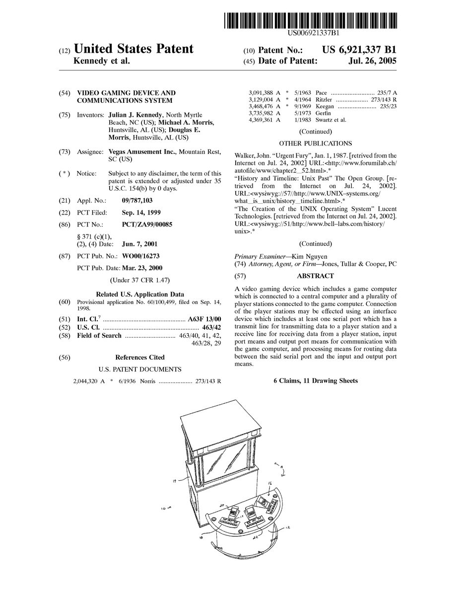
FIG. 1depicts a presently preferred embodiment of a multi-player interactive video gaming device, indicated generally at10. A cabinet A is divided into player portion12and a display portion14. Display portion14and player station12are attached by a connection piece (not visible in the view shown) through which communication and power lines may be passed. It should be understood, however, that various cabinet configurations are possible. For instance, the player portion and the display portion may be unitarily constructed. Multiplayer video gaming devices are described in U.S. Pat. No. 5,688,174 and U.S. patent applications Ser. No. 08/885,276 and 08/903,806. The entire disclosures of the '174 patent and the '276 and '086 applications are incorporated by reference herein for all purposes.
Player portion12is constructed to simulate a casino blackjack game table. Three player stations16are disposed on the top counter surface of player portion12. Each player station16includes a keypad18and a currency acceptor20. Each keypad18includes a plurality of input keys22through which players participate in the blackjack game. In the embodiment shown, the currency acceptor is a bill acceptor configured to receive bills of various denominations. The currency acceptor could also accost coins.
In this embodiment, each keypad lo includes a first row of five, and a second of two, input keys22. It should be understood by those ordinary skill in this art that the use, number, and arrangement of such keys an depend upon the nature of He video gaming program operated within the present invention. For example, a blackjack game may require she use of different keys for different purposes than a poker game. Bill acceptor20accepts bills or betting and/or game fee purposes.
A ticket dispenser19is mounted at each player station. Players may “cash out” at any rime by inputting a proper command at their player station. Upon cashing out, a printer mounted within the cabinet prints a redeemable ticket indicating the player's winnings via ticket dispenser19. In other embodiments, a single printer is provided in the cabinet to print redemption tickets for all players.
A functional illustration of a player station16is provided in FIG.2. As indicated above, the player station includes a plurality of input devices24, which may include, for example, player input buttons22and currency acceptor devices such as bill acceptors20(FIG.1). Player station16also includes output devices26, which may include lamps, digital output displays, meters and/or currency return s devices such as token dispensers or ticket dispensers19(FIG.1), which output currency to players in the form of redeemable tickets. Currency acceptor and return devices may include magnetic card readers/writers and IC card readers/writers to accept and/or pay out currency electronically.
Player input messages are transferred from the player stations to a workstation/including a game processor running the video gaming program. The workstation may include a data port, such as a serial port or a keyboard port, an input/output system, and a suitable communication arrangement communicating with a remote game computer. Accordingly, a workstation assembly may comprise a local computer, to receive input from a plurality of player stations, and a remote computer, to receive input signals from the local computer and execute the game program responsively to such signals. The local and remote computers may communicate through any suitable arrangement, for example telephone systems or local area network systems. The remote computer's game processor thereby receives input signals from the data port of the local computer. In this arrangement, a single game processor may operate a plurality of remote player station groups. Alternatively, a workstation assembly may comprise a remote computer and a communications system, such as a telephone system or local area network system, through which multiple player stations communicate with the remote computer. Thus, a plurality of single-player stations separated by relatively long distances may participate in a single-player or multi-player game operated by the remote computer.
Additionally, however, the workstation may be a personal computer assembly including an input/output system, one or more data ports and a game processor device in a local unit. As should be understood in this art, a personal computer is a relatively small, for example as compared to a main frame, computer that is typically designed for use by a single user or by multiple users through a network. It employs components such as a central processing unit (CPU), memory, and an input/output system by means of an operating system such as WINDOWS95. The CPU is an integrated circuit “chip” that can perform a multitude of operations. The input/output system manages data handling among the CPU and other internal or external components. Thus, the personal computer is a general purpose computer, as opposed to single-program “embedded” system, which may include a dedicated processor device mounted on a printed circuit board and configured to perform a single function. A personal computer assembly may be a board including a processor and an input/output system. It may also include a cabinet and/or various external and internal components, as should be understood in this art.
Because it is a multipurpose device, the personal computer assembly typically has no permanent input or output device having direct communication to the circuit board or, if there is more than one board, to the main circuit board. Instead, data is conveyed between input and output devices and the input/output system by data ports. These ports may have predetermined uses, for example to receive input from a keyboard or a mouse or to direct output to a printer or monitor. Personal computers also often include expansion slots for additional circuit boards which may, in turn, include their own data ports.
Although a personal computer assembly is the workstation type most often discussed herein, it should be understood that this is for exemplary purposes and that all workstation configurations, provided they are suitable for a given embodiment, are within the scope and spirit of the present invention. The remote computer in any of these arrangements may operate a progressive jackpot feature in which all communicating player stations may participate.
The player input message is the information input at the player station, for example by player activation of a button or bill acceptor or by system activation of a maintenance condition at a token dispenser, and conveyed to the personal computer through the player station and interface assembly equipment. During the transmission, the message may take a variety of forms. For example, in a preferred embodiment as illustrated in the figures, one type of player input message may be input by pressing a button22(FIG.1). As discussed in more detail below, this delivers a signal, for example a pulse, to the player station control mechanism, which identifies the pulse and selects an appropriate ASCII input code. The player station outputs the ASCII input code to the interface assembly, where the interface assembly control mechanism converts the input code to a scan code for transmission to the personal computer.
Another type of player input message may be input by activating a bill acceptor. The bill acceptors may deliver input signals to the player station control mechanism in a variety of forms, for example as a series of pulses or as a digital word. It should be understood that all such configurations are included within the scope and spirit of the present invention.
The internal components:of player station16are illustrated functionally inFIG. 2by player station processing system28, transmitting buffer30and receiving buffer32. In a preferred embodiment, processing system28receives data directly from input devices24. If many input devices are employed on a player station, however, it is possible to create a row/column matrix for routing data via multiplexing to the Processing system, as should be understood in this art.
In operation, if the processing system28detects, for example, a falling pulse indicating that is a particular button has been pressed, the processing system associates the pressing of that button with an appropriate code. In a present embodiment, the code is a four character message. The first character indicates that the message is beginning. The second character indicates the message type, which identifies the message as, for example, a button message or a dollar bill acceptor message. The third character provides the message information, for example that button number three has been pressed. The fourth character indicates the end of a message. The coding prevents information loss and/or message scrambling when the messages are queued or dequeued.
After creation of the appropriate code, the message is stored in transmitting buffer30. A serial port34is provided on player station16to output the data stored in buffer30. The serial port converts data from a parallel format to a serial format to transmit and converts from a serial format to a parallel format to receive. Status signals indicate whether the transmitter is available (empty) and whether the receiver contains data (full). Two data lines, transmit line36and receive line38, are connected to serial port34. Processing system28monitors a status signal associated with transmit line36. When a “transmitter empty” condition is indicated, the next message character in transmit buffer30is transmitted through serial port34along transmit line36.
Data received from receive line38through serial port34is stored in receive buffer32. Processing system28receives messages from buffer32and acts according to instructions provided thereby. Thus, processing system28may be caused to illuminate lamps at the player station, dispense coins through a token dispenser, print a cash out ticket, or other desired functions.
In a star arrangement, each player station16communicates with a central interface device for transferring player input messages to the game computer. As illustrated inFIG. 3, each player station communicates by its respective transmit line36and receive line38with an interface device or concentrator40via serial ports42. Five player stations may be employed within the .construction illustrated inFIG. 3, although less than five, for example three, may be used. In a daisy-chain arrangement as illustrated inFIG. 7, the player stations may be connected in tandem so that messages move in and out of successive player stations until reaching the central interface device. Each player station includes an additional serial port and buffer, and each player station processing system generates new messages to the next player station to pass on a message received from a prior player station.
Referring again toFIG. 3, interface40includes receive buffers44and transmit buffers46corresponding to each player station. An interface:
processing system48controls the transfer of an information between the receive buffers44and interface output buffer50and between an interface input buffer52and the transmit buffers46. When processing system48receives an incoming message from a receive buffer44, the processing system converts the message to a scan code which the operating system on the game computer will recognize. The scan codes are routed to and stored in transmit buffer50, which communicates with the game computer via interface keyboard port54. A transmit line56connects interface keyboard port54with a game computer keyboard port. Processing system48monitors transmit line56and, when no data is present on transmit line56, outputs the scan codes stored in transmit buffer50to the game computer over transmit line56through keyboard port54.
The scan codes are received by the game computer through its keyboard port. The use or the game computer keyboard port has certain advantages. For example, general purpose computers are Typically sold wit, operating systems configured to receive and recognize scan codes from the keyboard port. Thus, the game program may be constructed around the standard keyboard key strokes that the scan codes represent, and the video gaming programmer may rely on the built-in operating system to receive and process input data without having to program a custom data operating and error checking system. Some recent operating systems, for example WINDOWS95, receive and process data from operating system ports other than the keyboard port, for example certain COMM ports.
While the operating system does not recognize “key up” and “key down” events from these other ports, applications running on the operating system may otherwise take advantage of the operating system to deliver data from them. For illustrative purposes, not for purposes of limitation, communication by keyboard port is primarily discussed herein.
Data is routed between the player stations and the game computer through processing systems28and4B, illustrated inFIGS. 2 and 3, and the input and output buffer systems, without loss of information.
Thus, if two players press input buttons at their respective player stations simultaneously, both input messages will be received by the game computer.
Is Commands from the game computer to player station output devices are transmitted to interface input buffer52via interface device serial port58. Processing system48receives messages from buffer52, determines to which player station the command should be forwarded, and stores the command in the appropriate output buffer46for transmission to the player station via the corresponding serial port42. If the system is daisy-chained, only one transmit buffer is required. As each message is received by a player station, it is relayed to and examined by the next player station. If the message is found to be for this player station, that station's processing system performs the requested action.
Processing system48may also communicate directly with input devices24and output devices26.
These may include the same input and output devices discussed above with respect to the player stations.
That is, the input and output devices of a single player station may be directly connected to interface device40without a player station processing system28and buffers30and32(FIG. 2) that are associated with the individual multiple player stations. Thus, the game computer/interface assembly may be used with player stations of single player games which do not have such processing systems or buffers. Accordingly, the game computer/interface assembly may be used interchangeably with a multiplayer or a single player configuration. Video gaming machines may be constructed with removable player station units so that the game may be converted between a multi-player game and a single player game simply by interchanging the player station unit or units. Provision may be made to reprogram or convert the game computer to a new or previously or stored program to enable operation of the new game.
In another preferred embodiment, the interface device may be physically embodied on a player station so that player station communicates with the game computer through the keyboard port. Other player stations output messages to the game computer through this first player station to avoid loss of information. Player station units may be linked to the first player station in a star or daisy-chain arrangement and may be added or removed to achieve a desired number of player stations.
As described above, processing system48receives incoming codes from the player stations and converts the codes to scan codes which the operating system on the came computer will recognize. Since there are a finite number of messages which will come from any planer station, a unique scan code at be assigned to each Particular message from each player station.
This may be accomplished, for example, by converting player station messages into keyboard scan codes. Thus, in a preferred embodiment, each player station includes similar input devices in a similar arrangement and outputs the same messages for the same corresponding devices. Processing system48assigns scan codes based upon the player station message and the player station itself. Thus, the assignment of the scan code depends upon the particular message and the particular player station from which the message is received.
It should be understood, however, that various suitable configurations are possible. For example, while in a preferred embodiment the player station processing systems assign ASCII codes as the player station messages, various coding processes may be employed. Thus, for example, scan codes could be assigned at the individual player stations, eliminating the need to make the assignment at the interface device.
In the illustrated local unit embodiment, the game computer is, preferably, an IBM PC/AT compatible personal computer. Thus, the scan codes assigned by processing system48are compatible with the operating system provided on those computers. The operating system is configured to receive the scan codes from the computer keyboard port and to use those codes for operating system functions and/or higher level functions. In particular, the IBM PC AT compatible computers may receive the scan codes and convert them to ASCII codes, which may be output to a screen and which may be used in commercial or custom software, including the gaming program.
A schematic illustration of a player station is provided inFIG. 4. Aplurality of buttons, which for example may be installed in groups of up to eight buttons22(FIG.1), are indicated at60. Thus, if three button groups are used, the player station may include a total of24input buttons. A bill acceptor is controlled by a series of dip switches66, which may be used to program the bill acceptor to, for example, accept certain bill denominations and/or select serial or pulse mode operation.
Output devices includes lamp groups68and digital output groups72. As with the button groups, each lamp group and each digital output group includes eight lamps and eight digital output devices, respectively. It should be understood, however, that all of the available input and output devices may not necessarily be employed in a particular game; the exemplary construction illustrated inFIG. 4merely indicates that they are available. Other output devices include a token dispenser and/or ticket dispenser indicated at78.
Data is transmitted to or from these input and output devices on 8-bit data bus80and is controlled by field programmable gate array82. Gate array82may be, for example, a Xilinx XC3042 or XC5202 gate array; or other suitable device.
Data transfer from the player station is controlled by a processor84which, i one preferred embodiment, is an 8051-compatible microcomputer having one or two on-chip serial ports. It should be understood that other processing devices may be used, for example those including on-board EPROMs. Although processor84includes a certain amour: or memory, SRAM86provides additional storage. Together, this memory serves as the player station buffers. PROM88provides storage for the programming for processor84and the look-up tables by which input codes may be assigned to particular input signals. A PAL (not shown), for example a 20V8 PAL, is provided to decode the microprocessor address range into three ranges—EPROM, processor and input/output devices, including the gate array.
In operation, processor84controls gate array82to input and output data to and from the input devices and output devices. An internal logic signal of the gate array82causes gate array82to send an interrupt signal to processor84every25milliseconds. In response to this interrupt command, processor84orders gate array82to sequentially place the contents of the data registers of the respective button groups on data bus80. Thus, if a player presses one of the buttons in a particular button group, the corresponding position in the button group register in the gate array changes state. Following the next 25 millisecond interrupt signal, processor84causes gate array82to output the contents of that button group's register, in order among the other button groups, to common bus80. In the embodiment depicted inFIG. 4, a button group may include up to eight buttons so that each button position of the button group register may correspond to a data line on eight bit bus80. Thus, of the ago eight data lines input to processor84from bus80, seven are at a normal state while one has changed state due to the pressed button. Because processor84causes gate array82to output the button group registers to the common bus in a certain order, processor84knows which button group is connected to the common bus at any time. In this manner, the processor identifies the particular button group from which it receives an input message,. The particular button or buttons within the button group is determined by the line or lines on common bus80that have changed state.
Once processor84determines that a particular button in a particular button group has been pressed, it generates an ASCII code corresponding to that particular button. This can be done, for example, either by an algorithm that is part of the processor84program or according to a lookup table stored in EPROM88. Once the code is established, it is translated into a message which is stored in a transmit buffer in SRAM86until processor84determines that the serial transmitter89of serial port34is free. When the output line is free of data, processor84outputs the stored ASCII codes from SRAM86through serial port34to the output data line.
If two or more buttons in a button group are simultaneously pressed, processor84converts each signal into a corresponding ASCII code and stores signals in SRAM86according to a predetermined order, for example depending upon the data line over which they were received. The corresponding messages are output through serial port34in the order in which they are stored in SRAM86. By this protocol, simultaneous button activations are accommodated without information loss.
This assumes, however, that the activation of all the buttons represents information—data that the game program should receive to operate properly. In some games certain buttons, for example “Bet” or “Hit” buttons, are inappropriate at certain times. While the game program itself may be configured to ignore the data resulting from these button activations once such data is received, the program may control processors84and96/toFIG. 5mask these buttons so that the data is not forwarded to the game computer. Additionally, the processors may be programmed to recognize one or more button activations, and not recognize one or more others, when buttons are simultaneously activated where the latter buttons may always be ignored in favor of the former buttons. In any event, the video gaming device may be configured to ignore button activations which do not represent information while maintaining the ability to process those simultaneous button activations chat do.
Processor84may also receive inputs from bill acceptor20, token dispenser78and/or ticket dispenser19through the gate array. Alternatively, bill acceptor20may communicate directly with processor84through serial port85, as indicated by dashed line87. The inputs from bill acceptor20primarily relate to the amount of currency input by the player. Inputs from the token dispenser generally concern errors, for example that there are insufficient tokens in the dispenser. Inputs from ticket dispenser19may include error signals but may also include signals indicating, for example, that a ticket has been printed and dispensed.
These devices are programmed to output an appropriate message to gate array82in a predetermined format, for example ASCIL hexadecimal. Upon receipt of such a message, gate array82stores a digital signal indicating the origin of the message and sends a second interrupt signal co processor84. Upon receipt of this type of interrupt signal, processor84reads the identifying signal stored in gate array82and causes gate array82to pass the input from that particular device to common bus80where it is read by processor84. Processor84converts these messages, either by a program algorithm or by a lookup table, to an ASCII code which is output by serial port34.
Processor84may drive a parallel printer83to print redeemable coupons. This arrangement may be used in place of a ticket dispenser that outputs preprinted tickets in fixed denominations. In addition, a central printer driven by the game computer may be used instead of individual player station printers.
Data commands to a player station are received through serial port34by processor84, which stores the command in SRAM86. The command will identify a particular output device, for example ticket dispenser19or a lamp in a lamp group68. Assuming the latter, processor84writes appropriate data on bus80to drive the particular lamp, while preserving the previous state of the other lamps in the group, and instructs gate array82to apply this Instruction to the appropriate lamp group. Instructions to bill the acceptor20, token dispenser78and ticket dispenser19are generally in the form of digital words which are downloaded to the particular devices through gate array82. These output devices are configured to receive this information and act accordingly. The particular construction and configuration of these devices are well known in the art and need not be described herein.
Player station16also includes two nonvolatile RAM/real-time clocks91/and91A for maintaining data between power cycles and for power-off intrusion detection. The battery-powered devices remember hot many tokens are deposited during a vend cycle as the tokens are being deposited. Thus, if the machine is to deposit ten tokens, but power fails after only six are deposited, the NVRAM/RTCs91notify processor84and/or the game computer that four additional tokens should be deposited. As indicated inFIG. 4, NVRAM/RTCs91communicate with processor84through gate array82.
Two NVRAM/RTCs91are provided for error checking purposes. During a vend cycle, for example, one NVRAM/RTC91is incremented before a token is deposited, and the other is incremented after the token is deposited. Accordingly, following a power-up, a vend cycle or a token deposition, microprocessor84detects an error if the registers of the two NVRAM/RTCs do not agree. In this case, processor84, the game computer or a central computer may shut down further operations of the player station16until the error is resolved.
NVRAM/RTCs91also provide a security function.
In a preferred embodiment, switches are disposed at the game machine's money pit and electronics pit so that if the door to either is opened, a line is pulled low. Each line is connected to a respective NVRAM/RTC91so that if it goes low, the memory register for the respective NVRAM/RTC91is cleared. If processor84detects this condition, for example following power-up or after a periodic scan, an error is detected, and the processor or game computer stops the player station's activity until the error is resolved.
Further, upon detection of an error processor84may output an appropriate message through serial port34to a central computer that, in turn, may provide notification to an operator. In investigating and attempting to resolve the error, the operator may communicate with processor84through serial port93with an appropriate computer or other device. As indicated inFIG. 4, serial ports93and95are on-chip ports of processor84. Serial port95may be used as an alternative port by which to communicate with the central computer or other player stations, as discussed in more detail below.
Player stations16communicate with the game computer through a concentrator board40(FIG.3). A schematic illustration of concentrator board40is provided in FIG.5. In the star arrangement, each player station communicates with concentrator board40from the player station's serial port34(FIG. 4) to a serial port on the concentrator board. Four serial port groups90are provided on the concentrator board. Each serial port group90includes four serial ports, each having an input line and output line. Thus, each serial port group has eight data lines in communication with an eight bit data bus92. Accordingly, in the configuration illustrated inFIG. 5, sixteen player stations may be connected to concentrator board40, although in preferred embodiments three or five player stations are employed.
Field programmable gate array94controls communication of data along bus92between a processor96and the ports and devices communicating with the bus. Any suitable processing device, or example an 8051-compatible microcomputer, may be used. Gate array94, EPROM98and SRAM100may include the same or similar components as the corresponding components on the player stations.
EPROM98stores the program executed by processor96. Processor96may include its own internal memory for use as buffers. Preferably, however, SRAM100is included to provide additional memory.
A player input message from a particular player station is received at a serial port, which communicates with that player station, in one of the serial port groups90, where it is stored in the serial port group register. Upon receipt of an interrupt signal periodically sent by gate array94, processor96instructs gate array94to sequentially connect the register of each serial port group90to the eight data lines of common bus92. In this manner, processor96is able to determine from which serial port, and therefore from which player station, it receives data. Processor96stores the incoming data either in its internal memory or in SRAM100.
As discussed above, the incoming messages are in the form of ASCII codes. Processor96, either by computer program algorithm or by a look up table stored in EPROM98, assigns a scan code appropriate for the particular ASCII character from the particular player station. The scan code is then stored in SRAM100.
Processor96monitors the status of keyboard output port102by gate array94. If the output data line is clear, processor96outputs the stored scan code from SRAM100over bus92to gate array94to keyboard output port102. Keyboard output port102communicates with the game processor via a personal computer keyboard port.
Data may be downloaded from the game computer via a keyboard input port104or serial port106. If data is downloaded to keyboard input port104, gate array94sends a second interrupt signal to processor96, which then instructs gate array94to put the data on common bus92for storage in SRAM100. Data downloaded through serial port106is stored by processor96in SRAM100. If the incoming message is a command for a player station, processor96causes gate array94to connect the appropriate serial port in the appropriate serial port group90to common bus92and outputs the command to the common bus.
Concentrator board40also includes connections for button groups108and110, lamp group112, digital output device group114, switches116, bill acceptor116, token dispenser120, and ticket dispenser122. These connections are provided for direct connection of their associated devices to concentrator board40. Thus, concentrator board40may be configured to function as a single player station, operating as described above regarding player stations16(FIG.4). Thus, in a preferred embodiment, a game cabinet may be constructed housing a personal computer assembly and a concentrator board assembly wherein the player stations are removable. Thus, multiple player stations may be installed and connected to serial ports in serial port groups90for communication to the game computer through the concentrator board. The game may, however, be converted to a single player game by removal or deactivation of the multiple player stations and installation of a single player station whose components connect directly to the concentrator board40as indicated in FIG.5. Multiple alternative game and operating programs may be stored in, or programmed into, the game processor and the concentrator board processor so that they may operate in the new configuration. Thus, a game assembly may be convertible between a single player and a multiplayer configuration.
Although the button groups, serial ports, lamp groups and output device groups are illustrated inFIG. 5as being connected to bus92so that gate array94may selectively connect their registers to the bus, it should be understood that these devices may be connected to the bus through the gate array.
FIGS. 7 and 8illustrate a daisy-chain arrangement of the present invention. In the embodiment illustrated in these figures, a serial port of game computer124is the head of a bidirectional RS-232 network implemented using intelligent controller cards, each having two serial communications ports termed the “up” and “down” ports. In general, commands from the game computer flow first into the concentrator up port, the first external node in the network. Commands from the game computer are echoed to the concentrator down port and output to the first player station, player station16a, up port. If the command is intended for processing by this player station, the command message is parsed and queued. Otherwise, the message is echoed to the player station's down port and output to the next player station up port. Player input messages generated by the player station and player input messages received from other player stations through the player station's down port are queued and dequeued, for example in round-robin fashion, to the station's up port as complete messages as they become ready.
Command messages and player input messages are processed at the non-interrupt level. Serial port buffers are managed at the interrupt level. This prevents loss of data when the processor is busy with local tasks.
In this fashion, command messages are passed from the game computer to specific player stations, and input messages from the player stations are passed up to the game computer. The concentrator40receives command messages from the serial communications port of game computer124. It routes input messages from player stations to the game computer through its keyboard port. Thus, input messages may be directed to the computer as keyboard scan codes as described above.
Each of the tandemly-linked player stations illustrated inFIG. 7may be configured as shown inFIG. 4with the use of serial ports34and95. Thus, one of the serial ports is used as the up port, and the other is used as the down port. The up ports and down ports are bidirectional. Thus, assuming player station16illustrated inFIG. 4is player station station16billustrated inFIG. 7, the up serial port34receives command messages from, and outputs input messages to, the down port of prayer station16a, while the down port receives input messages from, and outputs command messages to, the up port of player station16c. Command messages received by the up port are stored in SRAM86. The command message includes an identifier indicating for which player station it is intended. Processor84reads the Identifier and, if the command message is intended for player station16b, acts upon the message as described above. If, however, the command message is intended for player station16c, processor84directs tie message to the down port for output to player station16c.
Player station16breceives input messages from player station16cthrough its down port and stores them in SRAM86. Since these messages are intended for the game computer, processor84directs them to player station16athrough the up port. The input messages from player station16bare also passed to player station16athrough the up port.
Processor84may simultaneously receive and store messages from its dual serial ports (the up and down ports). If a message is to be passed through the player station, processor84may simply direct the message from one serial port to the other, or it may place the message on SRAM86for output at a later time. In any event, a player station may process command and input messages received from external sources while generating its own input messages without losing information even if, for example, a command message and an input message are received at the same time a button is pressed at the player station. Thus, from the perspective of player station16b, the interface between it and game computer124is concentrator40and player station16a.
A receive-only serial device, such as sign142, may be connected on the end of the chain. The network messaging protocols may be designed to allow other devices to be connected without mutual interference. That is, the message formatting for the player station network may be different than that used by the sign, and the two protocols may coexist without interference.
FIG. 8illustrates one preferred player station network architecture. There are three distinct processing levels for handling network traffic. At the hardware level/113, two standard on-chip serial communications ports/113A and113B handle all data serialization and deserialization. At the interrupt level/115, the onboard processor handles characters received from or sent to the serial ports. At the interrupt level, the processor manages two receive buffers/115A and115B an two transmit buffers/115C,115D. At the applications level/117, where all of the application's code has the same execution priority, the processor queues and dequeued messages in three queues/117A,117B,117C. E input queue/117A holds parsed command messages for processing by the application firmware. Two output queues/117B,117C hold complete input messages from the player station to be passed, using an arbitrary prioritization scheme, to the up port's output buffer.
Round-robin prioritization, for example, may be used to empty the output queues.
The above description illustrates both a star and daisy-chain arrangement. The concentrator and player stations support either topology. While the concentrator arrangement may exhibit superior performance, the daisy-chain arrangement is, generally, less expensive. The choice among star, daisy-chain and a combination of the two arrangements will depend upon the requirements of a specific application.
Referring now toFIG. 6, personal computer assembly124houses a game processor such as a CPU126, for example a PENTIUM processor, for executing a blackjack gaming program responsively co the player input messages from player stations16(FIG.4). An input/output system such as a BIOS128receives the input messages from concentrator boar keyboard output port102(FIG. 5) by keyboard port130and bus132. BIOS128outputs a signal to CPU126over a bus134. As should be understood by those of ordinary skill in the art, BIOS128may decode or encode signals received by CPU126depending upon, for example, the configuration of the personal computer assembly.
Moreover, a variety of circuitry configurations are possible within the range of personal computers. For example, a variety of input/output, memory (for example RAM136), buses, and other devices may be arranged in various suitable configurations. Furthermore, various methods may be employed utilizing such devices and configurations in communicating information between keyboard port130, or other suitable data input port, and CPU126. It should be understood that all suitable such personal computer configurations may be employed in accordance with the present invention.
As it executes a video card gaming program, CPU126outputs video display signals to a monitor13B via a parallel port140. The video card gaming program executed by CPU126permits interactive participation by a plurality of players at player stations16(FIG.1).
The video card gaming program is preferably written in an “event-driven” language such a Visual Basic or Visual C. An event-driven program performs operations responsively to “events” such as the depression of a push button that, in turn, causes BIOS128to output a signal to CPU126. As should be understood by those of ordinary skill in this art, personal computers are generally equipped with operating systems which are configured to manage communication between the personal computer and the software programs. In particular, the operating system is configured to recognize certain signals, for example scan codes received by the keyboard port and to convert such signals into predetermined codes, for example ASCII codes, which may be utilized by the program. In a preferred embodiment, personal computer assembly124is an IBM-compatible system using a MSDOS-compatible operating system. The scan codes assigned by the concentrator board (FIG. 5) are converted by the operating system to ASCII codes which are utilized in operation of the video card gaming program.
Although a variety of card gaming programs may be utilized in accordance with the present invention, in one presently preferred embodiment CPU126is configured to execute a blackjack game wherein the gaming program generates a “dealer's” blackjack hand on monitor138that is visible to the players at the player stations. The players submit wagers, accept or reject card “hits,” and select game options via the keys at the player stations. The player's hands are displayed on monitor138along with the dealer's hand in a manner similar to the display of cards on a casino blackjack table. Various versions of the basic blackjack or “21” game are known and may be employed in accordance with the present invention.
Various types of metering devices may be employed within the system. For example, an “in” meter may be used co count the amount of money put into the gaming machine. The construction of such meters, which should be well understood in the industry, need not be described herein. Typically, however, the meter is a relatively simple counter which is incremented by pulses The in meter may be implemented within a system of meters101as shown in FIG.4. Thus, one or more such meters may communicate with common bus80directly or through gate array82.
In operation, the game computer may receive data from a player station's bill acceptor20corresponding to an amount of currency accepted. The game program recognizes this amount and causes the game computer or processor84to output an appropriate number of pulses to the in meter so that the in meter properly increments, thereby recording the amount of money input at the player station. The number of pulses sent to the meter depends upon the denomination by which the meter is to count. For example, if the machine accepts currency in dollar, or greater, increments, the meter may increment for each dollar input at the machine or player station. Thus, if a player inputs a five dollar bill, the meter is incremented five times.
By controlling the meter through the game program, various types of bill acceptors may be used, for example those which output data by pulses or by digitally formatted signals. Various types of currency may be accepted, for example paper, coins or electronic media.
Other such meters may be attached within the system in a similar fashion for other purposes. For example, the game program may increment an “out” meter to record the amount of money cashed out at the machine or player station, for example through a coin or bill hopper, ticket dispenser or electronic output mechanism. The program may also increment a “credits played” meter, to record how much money is wagered at a player station, and a “credits won” meter, to record if the amount of money returned to the player station as winnings. Additionally, switches may be provided at certain game doors, as described above, so that the game computer is notified of openings and/or closings. Upon notice of a door or drawer opening, the game computer may increment a meter installed for this purpose. Such an arrangement may serve a security purpose, since the game's owner or operator may monitor the meter to assure that the game has not been opened since the previous meter reading. It should therefore be apparent that various game “events” may be metered using the arrangement and construction of the present invention.
The meters may be employed in a variety of game configurations. For example, as described above, they may be used in conjunction with an interface assembly as described herein that facilitates communication between player stations and a workstation running the game. They may also be used, however, in arrangements without such an interface assembly, such as embedded systems or networked player stations not employing a common interface. In an embedded system, the meters can communicate with a dedicated processor on a printed circuit board directly, for example through direct wiring to the circuit board, or indirectly, for example through processors at the player stations. The dedicated processor can increment the meters appropriately as events, such as money in, money out, money wagered, money won and door openings or closings, occur. In the networked arrangement, the meters may be incremented by a server, either directly or through the player stations, or by player station processors.
As noted above, one or more meters may be employed to record data for each player station.
Alternatively, in a multi-player game, a group of meters may be used to record such data for the multiplayer game as a whole, rather than per player station. Such meters may be attached as peripheral devices to the concentrator board40(FIG. 5) or to one of the player stations. Furthermore, meter groups, whether for use with the gaming machine as a whole or with individual player station, may be placed on their own boards. Such a board may include, for example, a memory device, a microprocessor and, possibly, an FPGA. Its construction and operation would be similar to that of the player station16arrangement illustrated inFIG. 4, but on a smaller scare. In a star arrangement, such a board could communicate with an interface processing system48by a serial port42(FIG.3). In a daisy-chain arrangement, the meter board, or boards, may be linked with the player stations.
Moreover, the player stations themselves may be constructed by multiple such boards, each containing a certain group of input and/or output devices. Thus, a player station may have a board for its meters and a separate board for its buttons. In this manner, defective components may be replaced without requiring replacement of the entire player station hardware.
Further, a cabinet may be more easily reconfigured to play a different game which might require a different configuration of certain player station devices.
Moreover, it should be recognized that the hardware arrangements illustrated in the figures are for illustrative purposes only and are not intended to limit the present invention. For example, the gate arrays on the player stations and the concentrator board could be replaced with other appropriate circuitry. Accordingly, it should be understood that any suitable design is within the scope and spirit of the present invention.
FIG. 9illustrates a system in which video gaming machines may communicate with a central computer without a location controller. InFIG. 9, a multi-player video gaming machine10includes a game computer124(for example a personal computer) communicating with three player stations16through a concentrator board40in a star configuration. As noted above, game computer124receives information from, and outputs information to, each player station16. Thus, game computer124is able to calculate all metering data associated with each individual player station. Game computer124communicates this information to a central computer140through a modem142or, for example, a direct wire link from a data port on computer124. Modem142may be an onboard modem within computer124or a separate modem with which the computer communicates by a modem card.
In this manner, computer124provides security and activity information for each player station16. For example, messages from computer124to central computer140may include an address that identifies a given player station so that the central computer can identify the message with that player station and respond accordingly. For example, in systems where a location controller identifies a particular game by the port over which data is received and outputs serial data to the central computer identifying the game, the game computer124may be programmed to communicate with the central computer using the same protocol used between the central computer and the location controller. Thus, the present invention may replace a location controller in an existing system without requiring that the central computer be reprogrammed.
The game computer may provide a variety of data to the central computer. For instance, if game computer124receives a message from a player station that its money pit door has been opened without authorization, this information may be provided to central computer140so that the central computer may take appropriate action directed to that player station. For example, the central computer may direct an operator to the player station and/or instruct game computer over124over modem142to shut down operation of the player station. In the latter case, the return message from the central computer to game computer124includes an address or other code structure identifying the player station to which the instruction applies.
As noted above, game computer124receives all metering information, for example money in, money out, credits played and credits won, from player station16. It is therefore able to communicate this information to central computer140through modem142. If central computer140at any time determines that a player station16is operating improperly, for example by not maintaining an appropriate return ratio, the central computer may issue a command to game computer124to shut down that player station.
Concentrator board40may also communicate with single player video gaming machines144that would otherwise communicate with central computer140through a location controller. These are conventional video gaming machines configured to output serial data to a location controller. In this embodiment, however, the data line from each game144is directed to a serial port42(FIG. 3) of concentrator board40. As should be understood in this art, information directed to the location controller is provided in a standard protocol. Thus, the concentrator board processor is programmed to read such signals and to output signals to game computer124that include the information carried by the signals from the single player games and that identify the particular games144from which the information was received. If the single player games are not adapted to provide an identifying address or code in their output signals, the concentrator board processor may be programmed to add this information, identifying a game144by the particular serial port from which a signal was received. Game computer124may be programmed to output all signals, whether pertaining to player stations16or single player games144, in a format in which central computer140would expect to receive information from a location controller.
Central computer140may also issue instructions to shut down a game144that is not operating properly. Game computer124receives this instruction and outputs an appropriate signal to the concentrator board in response. The concentrator board processor then directs an appropriate instruction, for example in a format in which the game144would expect to receive such an instruction from a location controller, to the serial port corresponding to the appropriate game. Game computer124identifies the appropriate game144in its message co the concentrator board processor.
The system may also be effected in a daisy-chain arrangement. One such arrangement is illustrated in10FIG. 10, in which game computer124communicates with a first player station16which tandemly communicates with two downstream player stations. As discussed above with respect toFIG. 4, the first player station communicates with game computer124and the subsequent player station16through its serial ports34and95, and the second player station16communicates with the upstream and downstream player stations through its serial ports34and95. The final player station16communicates with its upstream player station and a concentrator board40through its ports34and95.
The concentrator board40may be constructed as illustrated inFIG. 3, except that the keyboard port54is not used. Specifically, concentrator board40communicates with the upstream player station16and each of the single player games144through respective serial ports42. When the concentrator board processor receives information from a particular game144, it identifies the game (either by data included in the message or by the identity of the particular serial port from which the information was received) and outputs a message to the upstream player station16that identifies the nature of the message (i.e., that it is intended for the game computer124rather than one of the player stations), the identity of the game144, and the message information. As discussed above with respect to daisy-chain configurations, the upstream player stations pass the message on to game computer124that, in turn, outputs an appropriate message carrying the information to central computer140. Central computer140may communicate with player stations16and single player games144through game computer124, which directs messages down the chain to a particular player station as discussed above or to concentrator board40for output to the serial port42(FIG. 3) corresponding to the particular game144.
As noted above, concentrator board40is able to operate player station components. Thus, rather than adding an additional board, concentrator board40may be used in place of the last player station16inFIG. 10while also directing message traffic to and from the games144.
As an alternative to the concentrator board arrangement illustrated inFIG. 10, each game144may be retrofit with a board having a processor, at least three serial ports and appropriate memory, for example using such components as described above regarding the player station board illustrated in FIG.4. It should be understood, however, that the game boards may employ any suitable circuitry, for example replacing the processor with suitable logic circuits.
The first game board serial port is used to communicate between the board and the game144. This function may require an additional serial port, one for input and one for output, depending on the game's configuration. The other two serial ports perform the “up” and “down” functions as described above with respect to daisy-chained player stations. That is, one serial port is used to communicate with downstream devices while the other is used to communicate with upstream devices. Thus, a message intended for a particular game144may be output from the last player station to subsequent game boards until the message reaches the board on the correct game. The message includes an address identifying the game so that it is recognized by the game board's processor, which then outputs an appropriate message to the game through the first serial port. Messages from the game144to the central computer are output through the game board first serial port and are directed by the game board processer to the game board up port for output to upstream game boards and player stations to the game computer124, which then communicates with central computer140. Tandemly linked player stations retrofit with such boards are schematically shown in FIG.11. In an alternate arrangement, the upstreammost game144may output directly to a data port of game computer124, as shown by a dotted line147.
As noted above, a single player video gaming machine may be constructed using a game computer and a single player station16or concentrator board40as discussed above with respect toFIGS. 4 and 5. In this case, any number of single player or multiplayer games may be daisy-chained together as shown in FIG.12. The game computer of each downstream game communicates with its adjacent upstream game by a data port on the upstream game's game computer or by a player station serial port. The game computer of the upstreammost game communicates with central computer140through a modem142or through a direct line connection from a data port of the game computer. Where enough serial ports are provided on the player stations, all upstream and downstream communications may be effected through player station serial ports.
Moreover, it should be understood that various suitable configurations are possible. For example, a game computer having USB technology can communicate with up to127serial devices on each USB port. Thus, a game computer having one or more USB ports could perform the function of concentrator board40in FIG.10. It should be understood that all suitable arrangements and component configurations are included within the scope and spirit of the present invention. Multiplayer video gaming devices in accordance with the present invention may be employed in existing systems having location controllers. Referring toFIG. 13, a multi-player game10includes a game computer124and three player stations16arranged in a daisy-chain configuration as discussed above. Referring also toFIG. 4, each player station has four serial ports. Two of the serial ports34and95function as the up and down ports. One of the other ports85and93, however, communicates with a location controller146. Player station processor84is configured, in conjunction with game computer124, to output information corresponding to each particular player station in the same output format as games144.
Thus, central computer140and location controller146are able to treat each player station16as if it were a separate game.
Instructions directed from the central computer to a player station through the location controller are detected by the player station processor84. Thus, processor84and/or game computer124is able to shut down the operation of a given player station16responsively to central computer140without affecting the operation of the other player stations.
An alternate embodiment is provided in FIG.14. Here, player stations16are disposed in a daisy-chain arrangement with respect to game computer124. Rather than communicating directly with each player station, however, location controller146receives player station information from a board148. Board148may include a processor, at least four serial ports and appropriate memory as described with regard to such components illustrated in FIG.4. It should be understood, however, that board148may employ any suitable circuitry, for example replacing the processor with suitable logic circuits.
Game computer124accumulates information associated with each player station and outputs messages specific to a given player station to one of the serial ports on board148. The board148processor receives these messages and directs an appropriate message to a particular serial port corresponding to a particular player station16. The game computer and/or the board148processor may configure the messages so that they are output at these serial ports in a format compatible with local controller146. Thus, local controller146sees three separate inputs corresponding to three separate player stations, permitting these player stations to be treated by central computer140as separate game machines.
The processor of board148is programmed to receive instructions from central computer140and to output an appropriate message identifying the intended player station16to game computer124so that game computer124may take appropriate actions with respect to that player station. Where the configuration of central computer140and location controller146permit, board148may be omitted so that game computer124may communicate with the central computer through the location controller over a single serial data line. Alternatively, location controller146may communicate with game computer124over three serial lines where game computer124includes sufficient serial ports. It should also be understood that the player stations ofFIGS. 13 and 14may be arranged in a star configuration.
While preferred embodiments of the invention have been described above, it should be understood that any and all equivalent realizations of the present invention are included within the scope and spirit thereof. The embodiments depicted are presented by way of example only and are not intended as limitations upon the present invention. Thus, while particular embodiments of the invention have been described and shown, it will be understood by those of ordinary skill in this art that the present invention is not limited thereto since many modifications can be made. Therefore, it is contemplated that any and all such embodiments are included in the present invention.
Claims
- A multi-player card gaming system comprising: a) a plurality of spatially separate player stations, each said player station including: at least one input device for allowing a player to enter game play selections into said system;a currency acceptor for entering currency to facilitate game play;a money pit door for gaming access to a money pit for collecting currency from said currency acceptor;at least one output device for communicating game play outcome to the player, and means for monitoring a plurality of events at said player station, said events at least including opening of said money pit door and entering an amount of currency into said currency acceptor;b) a game processor interfaced to said plurality of player stations;c) a single video display monitor connected to said game processor for displaying said game play of each player station together, and d) a remote computer interfaced to said game processor for monitoring events of multiple individual gaming machines;wherein, said game processor is programmed first to execute a multi-player video card gaming program in response to inputs received from said player station input devices and currency acceptors, determine an outcome of said gaming program for each said player station, display said outcome on said video display monitor and communicate said outcome to said player station output devices;and second, to receive player station event information from said event monitoring means in each said player station and, in response thereto, to send messages to said remote computer, each said message identifying a one of said player stations and an event at said one of said player stations;and, in response to receipt of a command from said remote computer to shut down one of said player stations, sending a shut down command to said one of said player stations;and, said remote computer is programmed to identify each of said player stations as a corresponding one of a plurality of separate gaming machines and, in response to receipt of a message from said game processor indicating improper operation of one of said player stations, sending a command to said game processor to shut down said one of said gaming machines, said command including information identifying which of said gaming machines is to be shut down.
- The system of claim 1 , wherein said remote computer is programmed, in response to receipt of a message from said gaming program that the money pit door of one of said player stations has been opened, to send a command to said game processor identifying said one of said player stations and commanding said game processor to shut down that one of said player stations.
- The system of claim 1 , wherein said game processor is implemented using a personal computer.
- The system of claim 3 , wherein each player station further includes a player station processor for generating personal computer compatible codes in response to actuation of said input devices or said currency acceptor, and inputting said codes into said game processor.
- The system of claim 1 , further including metering means for metering game play activity data as a whole for said multiplayer game and wherein said game processor further is programmed to send said game play activity data to said remote computer.
- A multi-player card gaming system comprising: a) a plurality of spatially separate player stations, each said player station including: at least one input device for allowing a player to enter game play selections into said system;a currency acceptor for entering currency to facilitate game play;a money pit door for gaining access to a money pit for collecting currency from said currency acceptor;at least one output device for communicating game play outcome to the player;means for monitoring a plurality of events at said player station, said events at least including opening of said money pit door and entering an amount of currency into said currency acceptor;and a player station processor for generating personal computer compatible codes in response to actuation of said input devices or said currency acceptor, or occurrence of any of said player station events;b) a game processor interfaced to said plurality of player stations and receiving said codes from each of said player station processors, said game processor being implemented by a personal computer;c) a single video display monitor interfaced to said game processor for displaying said game play of each player station together;d) a remote computer interfaced to said game processor for monitoring events of multiple individual gaming machines;and e) metering means for metering game play activity data as a whole for said multiplayer game;wherein, said game processor is programmed first to execute a multiplayer video card gaming program in response to inputs received from said player station input devices and currency acceptors, determine an outcome of said gaming program for each said player station, display said outcome on said video display monitor and communicate said outcome to said player station output devices;and second, to receive player station event information from said event monitoring means in each said player station and said game play activity data as a whole from said metering means and, in response thereto, send messages to said remote computer, each said message identifying either said game play activity data as a whole or a one of said player stations and an event at said one of said player stations;and, in response to receipt of a command from said remote computer to shut down one of said player stations, sending a shut down command to said one of said player stations;and, said remote computer is programmed to identify each of said player stations as a corresponding one of a plurality of separate gaming machines and in response to receipt of a message from said game processor indicating that the money pit door of one of said player stations has been opened, sending a command to said game processor to shut down said one of said player station,said command including information identifying which of said player stations is to be shut down.
Disclaimer: Data collected from the USPTO and may be malformed, incomplete, and/or otherwise inaccurate.