Illustrative Figure
Abstract
A video game system that includes a console and hand-held controllers with LCD screens. Each game operates in a simulated world populated with animated characters and static objects which are displayed on a TV screen, and are also displayed on the LCD screens of the hand-held controllers. While one part of the simulated world is displayed on the TV screen, different parts of the simulated world may appear on the LCD screens in a natural pictorial setting. Alternatively, some of the pictures displayed on LCD screens and TV screens may represent the same part of the simulated world at different times, or the same part at the same time. Pictures displayed on an LCD screen may appear concurrently or later on the TV screen. Objects and characters can be selected, moved, constructed, changed, or deleted by a player without revealing to other players these objects of interest or their disposition. This video game system will provide a new game experience in which hand-held controllers do more than just control a console game, and also do more than just a standalone hand-held game.
Description
DETAILED DESCRIPTION OF EXEMPLARY EMBODIMENTS FIG. 8shows an exemplary embodiment of a video game system118on which the video games of the present invention may be played. Video game system console42generates a video signal on cable41connected to TV set11, for display on TV screen56or on a video monitor (not shown) or similar common display seen by other players. Console42is also connected to one or more hand-held control units28and29or other user input devices by cables45or a wireless equivalent (not shown inFIG. 8) such as infrared, ultrasonic, RF waves, or other data communicating forms of energy. Console42is detailed inFIG. 16which shows an optical disk reader83for reading optical disks43in which tracks82of digital information, including game programs and data, are pressed and molded by a disk manufacturer. The improved control units28and29shown in FIG.8andFIG. 3(control unit29is the same design as unit28) include features not included in control units44and47shown in other drawings. This is done for clarity in the drawings and does not imply that any one control unit design is more or less suitable for the present invention, except where additional hardware features of control units28and29, such as touch pad24and touch screen23, are required for use in video games that make use of those hardware features. FIG. 1illustrates an exemplary game playing session in which two human game players10and12hold game control units44and47having LCD screens on which are displayed pictures, verbal expressions, and/or other visual images. Whenever a human player10presses push-button (button-switch)14, his hand-held control unit44generates on his LCD screen a miniature copy33of the large picture displayed on TV screen56, generated either from data already stored in control unit44, or from data transmitted from console42(FIG. 16) in response to a signal initiated by manually pressing button14. Miniature picture33may be a freeze-frame, or animated in sync with the TV picture at various display rates, or animated in slow ...
DETAILED DESCRIPTION OF EXEMPLARY EMBODIMENTS
FIG. 8shows an exemplary embodiment of a video game system118on which the video games of the present invention may be played. Video game system console42generates a video signal on cable41connected to TV set11, for display on TV screen56or on a video monitor (not shown) or similar common display seen by other players. Console42is also connected to one or more hand-held control units28and29or other user input devices by cables45or a wireless equivalent (not shown inFIG. 8) such as infrared, ultrasonic, RF waves, or other data communicating forms of energy. Console42is detailed inFIG. 16which shows an optical disk reader83for reading optical disks43in which tracks82of digital information, including game programs and data, are pressed and molded by a disk manufacturer.
The improved control units28and29shown in FIG.8andFIG. 3(control unit29is the same design as unit28) include features not included in control units44and47shown in other drawings. This is done for clarity in the drawings and does not imply that any one control unit design is more or less suitable for the present invention, except where additional hardware features of control units28and29, such as touch pad24and touch screen23, are required for use in video games that make use of those hardware features.
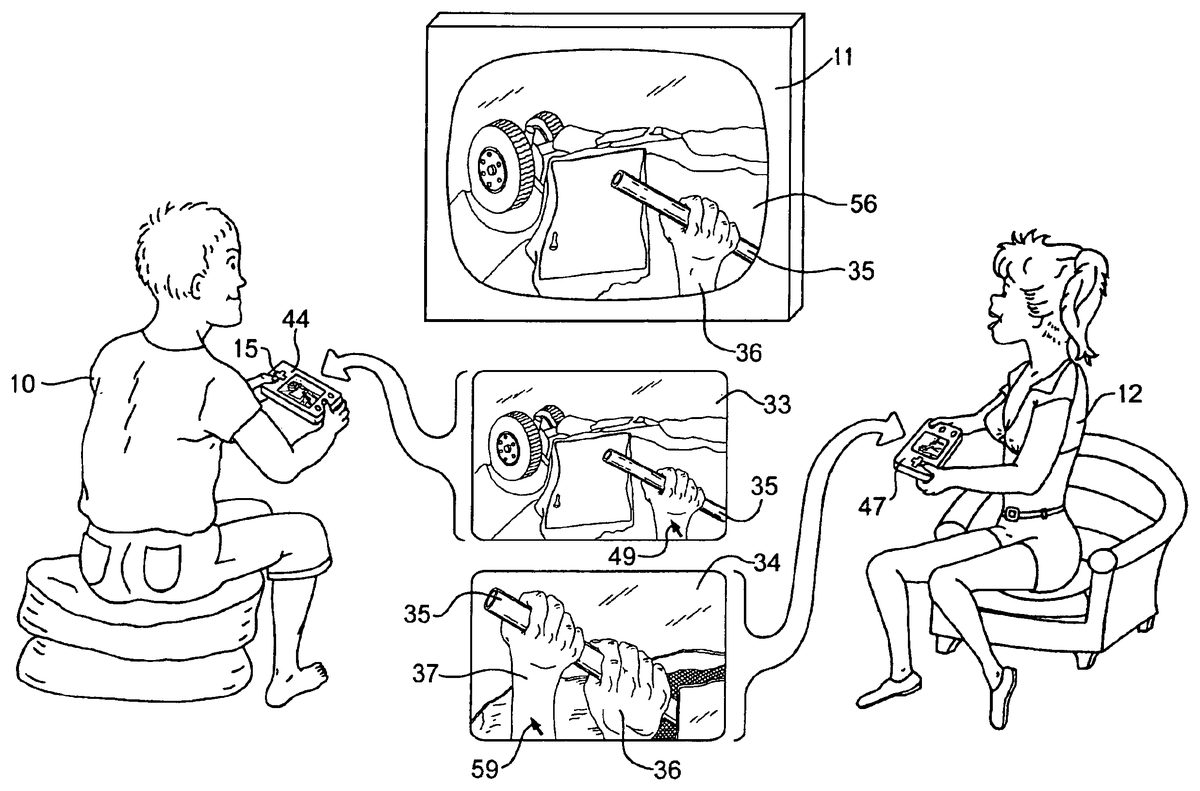
FIG. 1illustrates an exemplary game playing session in which two human game players10and12hold game control units44and47having LCD screens on which are displayed pictures, verbal expressions, and/or other visual images. Whenever a human player10presses push-button (button-switch)14, his hand-held control unit44generates on his LCD screen a miniature copy33of the large picture displayed on TV screen56, generated either from data already stored in control unit44, or from data transmitted from console42(FIG. 16) in response to a signal initiated by manually pressing button14. Miniature picture33may be a freeze-frame, or animated in sync with the TV picture at various display rates, or animated in slow or accelerated motion.
After miniature picture33is displayed on the LCD screen of control unit44, one or more areas25of the LCD screen may blink or change color or brightness or otherwise highlight or indicate areas of possible interest to player10. Player10may select a simulated object or area in picture33for further study by using cross-switch15to position a cursor, highlight, or other visual indicator to an LCD screen location corresponding to the indicated area25. Player10then selects the object or indicated location by pressing selection push-button57, which may cause the indicated area25to be enlarged on the LCD screen as picture34so that an object31that was previously invisible or too small to see on the LCD screen is made visible. Player10may then repeat the process by selecting object31which may be a written clue (with words that appear on control unit44) or a weapon to keep for future action, or other selectable objects. When objects are highlighted or enlarged on unit44, they typically are not highlighted or enlarged on TV screen56so that other human players such as player12will not see which objects have been selected on unit44.
Alternatively, player10, who does not normally control the dinosaur, may select the dinosaur's foot58that is blinking or otherwise indicated on the LCD screen of control unit44. When player10positions a cursor or other location indicator on foot58and presses selection button57, the action sequence of digitally generated pictures being displayed on TV screen56may, for example, cut to an alternative,action sequence showing the dinosaur stumbling and falling accompanied by sounds of the dinosaur hitting the ground and screaming in pain and anger, thereby allowing character17to escape from the dinosaur.
During the time that player10is pressing cross-switch15and buttons14and57, the action sequence showing the dinosaur chasing character17will continue and may reach a different branch point in the branching structure of action sequences that makes player10's selections moot. For example, player12may be making alternative choices that display different objects of interest on her control unit47and she may select different branches in the branching structure of action sequences that display alternative actions of character17or the dinosaur, or alternative scenes and characters.
Role-playing video games that make use of this invention will typically promote both cooperation and competition between game players. The exemplary game may promote cooperation between players10and12in trying to stop the dinosaur from attacking character17, but the game may also create competition between players10and12, both of whom may want to be first to rescue character17.
In many embodiments, miniature picture33is a freeze frame so that human player10may select an object25on the LCD screen before the object moves off screen.
FIG. 2illustrates an exemplary game playing session in which human player10has selected the miniature picture option described above with reference to FIG.1and has positioned cursor49onto the hand36of his player controlled character. The cursor appears only on miniature picture33and not on TV screen56. Player10has selected on his control unit44a hand-control mode in which he can control 3-dimensional movement of the hand of his player-controlled character. In the preferred control unit design shown inFIG. 3, hand-held control unit28includes at least one analog joystick20or21by which player10inFIG. 2may control 3-dimensional movement of his player-controlled character's right hand36or other selected body part. Details of a 2-shaft analog joystick to control motions of a player controlled character in 3-dimensions are disclosed in U.S. Pat. No. 6,186,896.
In the exemplary game illustrated inFIG. 2, player10has used cross-switch15to position his player character's right hand36to grasp steel pipe35for use as a prybar to open the door of a wrecked car shown in miniature picture33on the LCD screen of control unit44. When player10selects this option, his control unit44sends a data record (FIG. 19) to console42(FIG. 8) requesting a hand-grasping action sequence, and console42responds by generating a video frame sequence combining rendered polygons of moving hand36superimposed on the wrecked car background. Console42also generates a video signal for the generated frame sequence for display on TV screen56so that the other player12may see the hand-grasping action.
Simultaneously, control unit44generates an equivalent sequence of miniature animated pictures of moving hand36superimposed on the same wrecked car background on the LCD screen of control unit44. After the sequence of miniature animated pictures33and the frame sequence of video pictures shown on TV screen56begin, both sequences continue and remain substantially in sync, although perhaps at a different display rate, until player10selects other images for viewing on his control unit44, or another player12alters the moving picture sequence on TV screen56. The moving pictures on TV screen56of hand36grasping pipe35are visible to other human player12with no indication on TV screen56that any cursor control was used to cause the hand-grasping action sequence.
Human player12has selected (as will be explained below with reference toFIG. 15) an action from a picture menu (FIG. 15or15a) of alternative actions displayed on her control unit47. This selected action enables player12to position her cursor59(FIG. 2) on the right hand37of her player-controlled character to add her character's simulated pulling force to pipe35. When player12selects an action from a picture menu, her control unit47displays a miniature preview picture34on the LCD of her control unit47showing what will happen if she implements her selected action.
To accomplish this, her control unit47generates and displays an action sequence showing two hands59and36successfully pulling on pipe35. This preview sequence can be generated in simplified, low-resolution, fast-motion form, to give player12a quick preview of the selected (but not yet implemented) action sequence that will appear on TV screen56if she implements it.
In the exemplaryFIG. 2game, if player12implements the selected action by pressing on an appropriate push-button, her control unit47sends a selection data record (FIG. 19) to console42(FIG. 8) which generates the frame sequence being displayed on TV screen56and will, for example, generate a modified frame sequence showing her player-controlled character's right hand37grasping pipe35beside the other character's right hand36followed by a picture sequence showing both player-controlled characters prying open the wrecked car door and rescuing a non-player character (not shown) in the wrecked car.
Likewise inFIG. 1, player10may rerun prior scene34on LCD22so that he may make use of clue31or pickup tools he neglected earlier. Button-switches14may provide rewind, normal speed, and fast forward control of pictures displayed on LCD22for manual selection of objects and clues from prior scenes.
FIG. 3shows an improved hand-held control unit28which overcomes some of the difficulties a player might have selecting actions and objects on an LCD screen using only cross-switch15and push-buttons14and57on the hand-held control units44and47illustrated in FIG.1and FIG.2. The exemplaryFIG. 3control unit includes cross-switch15, two analog joysticks20and21, push-buttons57,14and other buttons, speaker27, external memory cartridge16, touch-sensitive pad24, and LCD22covered with transparent touchscreen23(shown in FIG.4).
Touchpad24and touchscreen23are sensitive to finger pressure and can measure the approximate location of a finger on X-Y coordinates as described below with reference to FIG.11. Transparent touchscreen technology is described in U.S. Pat. No. 6,163,313. InFIG. 3herein, both touchpad24and touchscreen23are specified for control unit28so that a player can use fingers of both hands to maneuver virtual objects in 3-dimensional space on LCD screen22. A player can select an object on touchscreen23with one finger, and while holding his finger steadily on the object, use another finger on touchpad24to rotate the object into the desired position. Touchpad24and touchscreen23can also act as push-buttons by accepting a finger tap, for example, of a few hundred milliseconds as a selection indicator.
FIG. 4is a block diagram of theFIG. 3control unit28which connects to console42through connector40and cable45or wireless equivalent. Control unit28which is only schematically represented inFIG. 4includes touchscreen23, touchpad24, and controller processor51for determining finger locations on touchscreen23and touchpad24. Processor51outputs X and Y coordinates to processor50which generates all pictures and text that appear on LCD22via LCD driver119, and generates data records (FIG. 19) that processor50sends to console42. Processor50also interprets all data records received from console42including records containing data from which processor generates pictures for display on LCD22. Memory security processor52controls all data passing between processor50and external memory cartridge16to verify authenticity of cartridge16. Memory cartridge security processors are disclosed in U.S. Pat. No. 6,190,257. Memory cartridge16is typically used when control unit28is used as a stand-alone hand-held game system.
When electric power to control unit28is turned on, boot ROM76provides an initial program of instructions, including some programs listed in FIG.20. Additional programs are loaded into RAM53and are supplied by console42which reads these control unit programs from disk43. See further discussion of these programs below with reference toFIGS. 19,20, and21.
Control unit28may include various other features such as an operating system in ROM76, a ROM and battery-maintained RAM in external memory cartridge16, a data bus, an address bus, input/output processor, image processing unit, communication control unit, power source, circuit board, and other customary components.
FIG. 5illustrates a slow method of entering numbers, without using a keyboard, by pressing cross-switch15repeatedly to move highlight cursor48horizontally and vertically on LCD screen22until a desired digit is highlighted. Pressing button57enters the selected digit. After all digits have been entered, button57is pressed again to enter the multi-digit number. This method is often too slow for games that require entering numbers, such as map coordinates for war games. Using analog joystick20is typically faster but less accurate, because pressing the joystick a little too far causes the highlight cursor to overshoot the desired digit.
FIG. 6illustrates a faster method of entering digits using touchscreen23overlaying LCD22. After selecting a series of digits by touching the digits, button57is pressed only once to enter the multi-digit number. For games that are downloaded from the Internet after payment by credit card, the touchscreen method illustrated inFIG. 6, for entering credit card numbers, is the preferred method, because entry of such numbers can be easily kept hidden from other people when entered on a hand-held control unit. Connector40for communications between control unit47and game console42may be connected to wires in cable45, or an RF transceiver, or a transceiver using infrared photodiodes38.
FIG. 7illustrates use of touchscreen23to replace the cursor control described above with reference to FIG.2. Instead of using cross-switch15inFIG. 2to position cursor49on hand36or cursor59on hand37, the preferred method inFIG. 7is for human player12to touch her finger to touchscreen23overlying the LCD image of hand37and slide her finger across touchscreen23to a new location over pipe35to cause corresponding movement of hand37grasping pipe35. Touchscreen23signals the finger location to controller51(FIG.4), which converts the location to physical X,Y coordinates, which processor50uses to calculate a new LCD location for displaying hand37. Thus simulated hand37will follow the player's moving finger on the touchscreen without any need for a cursor. The image of hand37substitutes for a cursor. When the location of hand37is within preprogrammed coordinates for pipe35, processor50(FIG. 4) recomputes the pixels representing hand37in successive frames, so that the hand appears to grasp and move pipe35displayed on the LCD. See further discussion below with reference to FIG.11.
Processor50also sends a series of data records to console42selecting a branch in the branching structure of alternative sequences of hand movements, showing hand37moving to the location of pipe35, rotating to a new angle facing pipe35, and grasping pipe35, the image of which is separately generated with the corresponding size and orientation. Microprocessor86(FIG. 16) or graphics coprocessor (not shown) in console42then generates the corresponding sequence of rendered polygons for hand37and pipe35for including in the video frame sequence. With thisFIG. 7method, players can use their hand-held controllers to indicate movement of objects to new locations in 3-dimensions and indicate actions to be performed which are then typically generated as composite video by generator117(FIG. 16) and appear on TV screen56for both players10and12to see.
FIG. 8shows an exemplary video game system118in general which includes two of the improved control units28and29as described above with reference to FIG.3.
Prior-art hardware shown inFIG. 9(from my U.S. Pat. No. 5,358,259) is included herein for comparison with FIG.8. LCD screens,22are illustrated inFIG. 8showing pictures, in contrast withFIG. 9LCD screens13which show menus of verbal expressions. For clarity, other differences in hardware, software, and methods are not all shown inFIGS. 8 and 9.
FIG. 10shows a control unit47with touchscreen23and a picture menu of emotional faces. By touching one face32, human player12can select the desired emotion or mood of a player-controlled character.
FIG. 11illustrates manual use of touchscreen23with X,Y coordinates for indicating a two-dimensional location on the underlying LCD screen22(FIG.4).FIG. 11shows hand37shaped as a fist and located at coordinates (X1Y1). When human player12places her finger over the image of hand37on touchscreen23and moves her finger on touchscreen23in the direction of the arrow to location (X2Y2)—the hand image on LCD22follows her finger as described above with reference to FIG.7. Pipe35intersects coordinates (X2Y2) and hence when hand37intersects pipe35at coordinates (X2Y2) the program being executed in microprocessor50in control unit47interprets this collision as a command to show hand37grasping whatever object is at coordinates (X2Y2)—in this example pipe35. The polygons which form the image of hand37on LCD22are then modified by microprocessor50(FIG. 4) to show hand37grasping pipe35on LCD22. If player12implements this action, microprocessor50sends data to console42where microprocessor86(FIG. 16) modifies corresponding polygons which form the image of hand37in the generated video images displayed on TV11(FIG.16). Hence, when touchscreen23is used to move an object in the picture on LCD22from one LCD location to another location, the resulting action appears on both the LCD22and TV screen56.
The X,Y coordinates inFIG. 11may be denominated in pixels or millimeters and refer to the visible area of LCD screen22and corresponding area of touchscreen23. Since the picture on LCD22is a two-dimensional picture, there is no Z coordinate, although Z may represent a non-spatial variable such as finger pressure. The X,Y coordinates on LCD screen22should not be confused with simulated coordinates X,Y,Z in a simulated 3-dimensional world populated with animated characters, a world in which Z represents height.
FIG. 12illustrates another use of cursor control in a war game where a first human player uses touchpad24(FIG. 3) to control cursor49on hand-held control unit28(FIG.3). He first uses touchpad24to position cursor49at a map location indicated by the + sign. Then he presses button14(FIG. 3) to define the starting point of a line of defense. Then using touchpad24to position cursor49as shown inFIG. 12, he presses button14again to define the end point of the defense line. Control unit28then displays a line of dots30inFIG. 13representing a line of soldiers. The first player can also indicate building a barrier across bridge39(FIG. 13) using cursor49(FIG.13). Since these tactical moves are displayed only on the first player's control unit, the line of soldiers and the bridge barrier are secret from a second player or players who may falsely assume that the soldiers are deployed elsewhere and bridge39is open. If the first player displays the map later, the same line of soldiers30and barrier on bridge39will continue to appear on the LCD screen of the first player's control unit, but will not be displayed on corresponding maps displayed on control units held by other players.
FIG. 14illustrates a map with a limited display area74that can be scrolled in various directions by using cross-switch15to display a different area of the map such as display area75which may show greater detail thanFIG. 13on the same size LCD22. Moving a finger on touchpad24or touchscreen23may be used in lieu of cross-switch15to relocate the display area on a map.
Thus control units with touchpads24and LCD screens22as illustrated inFIG. 3are very useful to control a video war game where the battles are displayed on TV screen56(FIG. 2) for all players to see, but where tactical moves are planned and executed in secret on hand-held control units. Performing the same functions with cross-switch15on control unit44as inFIG. 2would typically be less natural, more difficult, and slow.
FIG. 15illustrates a menu of alternative actions which appears on LCD screen22awaiting selection by human player12. LCD screen22is overlaid by touchscreen23(FIG. 4) so that the next action for character18to perform among these four alternative actions is selected by player12touching the touchscreen23. Character18in each of the four action pictures may be the same character, a player controlled character who is controlled by player12. When player12touches one of the four touchscreen areas corresponding to the four pictures inFIG. 15, control unit28(FIG. 8) or47(FIG. 1) generates data indicating which of the four corresponding locations is selected. Console42(FIG. 8) then begins one of the four possible action sequences selectable at the current branch point, i.e. one of the four preprogrammed actions. For control units that have LCD22but not touchscreen23, the procedure described above with reference toFIG. 5using a cross-switch may be used instead of a touchscreen.
FIG. 15aillustrates a menu of alternative actions which appear on LCD screen22as a series of pictures, each picture representing one alternative action for the character to perform. In this example there is no touchscreen23overlaying LCD22and human player12cycles through the series of pictures until the desired action appears on the screen22.
FIG. 16is a block diagram of the major components of the exemplary video game system indicated generally at19and also shown inFIG. 8(FIG.8andFIG. 16show different hand-held control units). Game console42includes a housing indicated by the dashed line in FIG.16and shown in isometric view in FIG.8. Disk43is shown outside this housing for clarity, but may be played within the housing. Inside this housing is a small computer consisting of microprocessor86, RAM90for storing video game programs and data, boot ROM91for power up and reset and may include an operating system such as DOS, nonvolatile EPROM89, EEPROM, or battery-maintained SRAM for storing digital information that is different for each game console42, video signal generator117(see U.S. Pat. No. 6,139,433) for generating composite or separate audio and video suitable for input to TV set11or a video monitor (not shown), and peripheral interface chip88for sending and receiving digital data to and from hand-held control units44and47(FIG. 1) and control units28and29(FIG.8).
For clarity, specialized coprocessors for D/A conversion, audio, or for rendering texture-mapped polygons, terrain rendering, and related graphics processing are not shown.
Disk reader83reads digital information from plastic optical disks such as disk43in which the digital information is molded and burned. Disk reader83reads this digital information from two areas of disk43: from area81and from area80. In area81the digital information is represented as a long spiral track or tracks82of microscopic pits that are molded into each disk by a disk manufacturer. Digital information in area81includes video game programs and data. Area80, known as the burst cutting area (BCA), typically consists of a circular series of variable-width bar codes that are burned, melted, or heated by a medium power laser beam into each disk after they are molded by the manufacturer. This heating process permanently alters reflectivity of bar-shaped areas of a reflective layer in the disk. The word “burned” will be used herein to encompass the various methods for placing a substantially unique bar code (for each game product) onto each disk, even though the reflective layer is usually not burned through but merely darkened. More than a hundred patents have been issued for optical disks, BCA, and related technology, such U.S. Pat. No. 6,081,785.
In the BCA bar code, each variable width bar represents one bit. The maximum number of bits in the BCA is limited to 1,504 bits (188 bytes) under the current standard. Eighty BCA bits are sufficient for authentication because in the exemplary embodiment, the BCA bits are a block-encrypted cipher of a serial number and another number used for verifying authenticity.
Much of the digital information read from disk43by disk reader83is controlled by security processor chip84so that chip84can block processing of video game data from unauthorized disks. An exemplary security chip84is further detailed in FIG.17.
FIG. 17shows the video game system ofFIG. 16, but with more details on security chip84and processing of BCA data. Security chip84is a microcontroller with an on-chip microprocessor (not shown) for executing instructions from an on-chip ROM (not shown) to perform functions shown in FIG.17.
If all authenticating data were in the BCA bar code burned into each disk, then software pirates could easily defeat authentication by copying BCA's from authentic disks to non-authentic disks. It is therefore preferable for disk reader83to distinguish at least two physically different types of authenticating data which are shown inFIG. 17as burned bar codes80and molded lead-in control data track148. In this example, disk reader83accepts data from track148only if it a molded track with the standard optical properties of molded pits, i.e. not burned or a writable CD. There are numerous ways of making bar codes80and molded track148physically different. A simple way to make them different is to mold control data148into the disk during the same manufacturing step that molded area81. Mere separation of the burned80data from the molded148data on different optical tracks or writing some of the data onto a magnetic track would provide little security.
In this example, disk reader83distinguishes molded data from burned data in the BCA and this is indicated inFIG. 17by separate lines through disk reader83, one line from molded control data track148, a second line from molded program and data tracks82, and a third line from burned bar codes80.
In this example, data from molded control data track148includes an encrypted hash value144computed from game programs and/or data on tracks82during manufacturing (discussed below with reference to FIG.18). This encrypted hash value144is encrypted by the game vendor using a non-symmetrical “public key” cryptographic system as a digital signature. RSA, ECC, or other public-key cryptosystems may be used and are typically controlled by a private and public key of about 1,020 bits and typically produce an encrypted ciphertext of more than 1,020 bits. This ciphertext (encrypted hash value144) is molded into control track148. MD5, SHA-1 or similar hashing methods may be used to compute the hash value which may consist of 128-bit, 160-bit, or other size binary numbers before being encrypted. Decryption process107uses the same cryptographic method to decrypt value144under control of “public key”95to produce the original hash value145. In this example there is no need for public key95to be revealed to the public.
Data from burned BCA bar codes80includes encrypted control record94. In this example, encrypted control record94consists of at least 88 bits and preferably 128 bits and is encrypted by the game vendor using a symmetric block encryption method such as the Data Encryption Standard (DES), AES, or equivalent, so that changing any one bit of plaintext affects all bits of ciphertext, without providing clues that would lead to discovery of the bit values of the secret key K2through chosen plaintext attack or chosen ciphertext attack. Secret key K2is securely stored in security processor chip84, preferably in EPROM98, or EEPROM that is physically protected against chip peeling and scanning electron microscopy. Key K2is not externally readable from chip84. DES is described in detail in the Federal Register 40FR12134, Mar. 17, 1975. Simplified variations of DES may be used for block decryption process (99inFIG. 17) and the corresponding block encryption process (147in FIG.18).
Block decryption process99decrypts encrypted control record94under control of secret key K2(98) to produce a block of decrypted data including serial number101and secret key K1(reference number100). One-way hashing process108calculates a hash value from key100hashed together with all or selected portions of the programs and/or data read from tracks82into RAM96.
Processor instructions106, stored and executed in security chip84, compare decrypted hash value145to calculated hash value112. If the two numbers are equal, security chip84permits further reading of programs and data from disk tracks82into RAM96for execution by microprocessor86. If hash values112and145are different, then process26will block further reading of disk43, perhaps by endless looping.
Block decryption process99uses the same secret key98for decryption99(FIG. 17) as for encryption147(FIG.18). Typically this key98is at least 64 bits and preferably 80 bits. In the preferred embodiment, there is not one master key on chip84, because if it were compromised, perhaps by an employee or contractor of the game vendor, security chip84would become useless. Instead, in the preferred embodiment, each security chip includes a table of keys (not shown) so that secret key98can be changed in mid production of any game title by changing to a different key in the table. If the key bits in EPROM98are intermingled with unused random bits, anybody who accesses the bits will not know which bits are key bits without also reading the on-chip ROM program that knows which bits are key and which are decoys. If key EPROM98is mask programmed, that would reduce security of the keys.
Whenever process99decrypts encrypted control record94, one of the decrypted data fields is serial number101. Therefore in the preferred embodiment, chip84includes a process for comparing serial number101against table (not shown) of known invalid serial numbers, i.e. serial numbers that have been found on illegally copied game disks. If serial number101is invalid, then process26will block further reading of disk43.
Security chip84is designed to authenticate game disks such as disk43, but not to protect the programs and data on the disk from reverse engineering. In this embodiment, it is assumed that game programs and data on tracks82are not encrypted. However, in the preferred embodiment, at least a portion of the programs/data on tracks82should be encrypted to deter pirates from bypassing security chip84. Improvements may be added to security chip84to decrypt encrypted programs and/or data and other methods of improving security. The details of security chip84are given here only as examples and numerous other designs may be used.
FIG. 18shows a disk manufacturer's process for writing data onto disk43. Programs and data96are molded as tracks82into disk43by disk molding process149. During the same molding process, encrypted hash value144is also molded into disk43in lead-in control track148. Encrypted hash value144is previously computed by the game vendor as follows: Key K1(reference number100) is generated as a random number. One-way hashing process108then calculates a hash value145from key100hashed together with all or selected portions of the programs and/or data in RAM96. MD5, SHA-1 or similar hashing methods may be used to compute hash value145which may consist of 128-bit, 160-bit, or other size binary numbers. Any attempt to alter even one bit of the hashed programs and/or data will result in a different hash value145.
This hash value145is then encrypted under control of private key166using the same non-symmetrical “public key” cryptographic process discussed above with reference to FIG.17. The results of encryption process167is encrypted hash value144which is then molded into control track148. RSA, ECC, DH, or other public-key cryptosystems may be used for encryption process167.
Serial number101and key K1(reference100) are encrypted together (as a block) by block encryption process147under control of secret key98(key K2) to produce encrypted control record94. Encrypted control record94is then burned into BCA bar codes80in disk43by BCA burner150, using a different serial number101for each disk43. This makes the BCA bar code substantially unique for each of the disks.
FIG. 19shows a record format of exemplary data records use for communication between processor50in control unit28and microprocessor86in console42by way of cable45or equivalent. Each record78consists of several data fields including a control unit identification number so that console42will know which control unit generated record78, a picture serial number so that console42will know which video frame is being referred to, and a size factor number so that console42will know the degree of enlargement so it can relate LCD screen locations to simulated objects in the picture. Each record78has an operation code which specifies the type of data and what type of processing is to be performed.
Examples of operation codes include:00 initial power up01 identify location and size factor of displayed picture02 move object located at (X1Y1) to location (X2Y2)03 first person approach to object located at (X1Y1)04 build object id3between locations (X1Y1) and (X2Y2)05 change object located at (X1Y1) with object id306 destroy objects between (X1Y1) and (X2Y2)07 show hand grasping object at (X1Y1)08 show object at (X1Y1) entering object at (X2Y2)09 enlarge object located at (X1Y1)10 change camera angle to center on object at (X1Y1)11 retreat from object at (X1Y1)12 selection from action menu13 cancel or undo previous action serial number nnn
Since the above X,Y coordinates typically refer to physical locations (in pixels or millimeters) on LCD22and not always to spatial coordinates X,Y,Z in the simulated world of the animated characters, there is no Z spatial coordinate in theFIG. 19record format. However, if control unit processor50(FIG. 4) can convert physical LCD location coordinates into simulated spatial coordinates and send this data to console42, then the location data inFIG. 19would change accordingly. If processor50can determine the character action corresponding to a LCD location and send this action data to console42, theFIG. 19record would include numbers specifying selected actions.
FIG. 20is a memory map of various programs and data in RAM53in control unit28(FIG.4). Many of the functions performed by these programs are combined in the flowchart in FIG.21.
FIG. 21is an exemplary flow chart illustrating a sequence of functions performed by some of the programs temporarily stored in RAM53in control unit28.FIG. 21begins with program process60which executes out of ROM76and converts any initial manual inputs into numbers in memory to be sent to console42. For example, a player may hold down button14as he or she turns on electric power to control unit28to activate previously stored game status data. Then in program process61(operating out of ROM76) processor50sends a power-up data record (operation code 00) to console42which requests that console42send initial programs (read from disk43) to control unit28for storage in RAM53. When those programs are stored, processor50continues with program62which processes picture data records received from console42.
Process63then generates a picture for display on LCD22that is a miniature likeness of the TV frame currently displayed on TV screen56. Process64then displays the miniature likeness picture on LCD22. The control unit program then enters a program loop which checks (decision boxes65,66,67) for any manual input from a cross-switch, joystick, touchscreen, touchpad, or button switches to determine which kind of location data to send to console42(boxes68,69,70). Control unit processor50then sends a location data record (or other type of record) to console42. The interrupt feature of processor50may be used to insure that loops shown inFIG. 21do not interfere with other functions performed by processor50.
Processor50in control unit28may generate many of the picture sequences with infrequent guidance from console42, especially during time intervals when the pictures displayed on LCD22are not being displayed on TV screen56. For example in a war game (referring toFIGS. 12,13, and14), strategic and tactical planning may be controlled by each player on separate hand-held control units44and47. Because these private pictures and/or words are not shared with other players by way of TV screen56, there is no need for frequent sending of data records back and forth between control units and console42during these private phases of the interactive game. During this private phase, each control unit acts independently of console42, executing programs for planning, deployment of soldiers, movement of supplies, building of bridges, destroying enemy barriers, reconnaissance, displaying reports from spies etc, while the TV screen shows generic scenes and information already known to both sides, such as maps of recent battles, or animated characters controlled by other players.
During game phases where the TV pictures are related to the LCD pictures, there will be much sending and receiving of data records between control units and console42. During these shared phases, console42programs in RAM90(FIG. 16) determine what is to be displayed on each control unit28,44, etc. and generate picture or program data records which microprocessor86sends to one or the other control units. When a control unit receives a data record from console42, decision box73transfers control to process62which processes the received picture data record. If data records from console42contains program instructions, process62in this example will load the downloaded program into RAM53for execution in the control unit processor50.
FIGS. 22 and 23illustrate the relationship between video pictures on TV screen56and a miniature likeness being displayed on LCD screen22. InFIG. 22a large detailed picture is being displayed on TV screen56. If this detailed picture is greatly reduced in size (perhaps by 90%) for display on a small LCD screen22on a hand-held control unit28, many of the details may be lost and the miniature picture may become unintelligible.
FIG. 23aillustrates this loss of detail. One way of avoiding this problem is for processor50to generate wider lines and other details as inFIG. 23bfrom compressed data supplied by console42. The LCD picture33inFIG. 23bis a miniature likeness for display on LCD22and does not have to be an exact copy of the TV screen picture reduced in size. Another method is illustrated in theFIG. 23cpicture which consists of about 250 short line segments that together form a simplified likeness of the picture on TV screen56and omits fine textures displayed on TV screen56. Further simplified pictures may be used on LCD22.
FIG. 24shows an exemplary and simplified block diagram of system19showing how data flows between console42and a hand-held control unit28. When disk reader83reads game programs into RAM90, the programs in this example are of two kinds, console program(s)151with associated data, and controller program(s)152with associated data. Focusing on the programs, controller program152is transmitted to RAM53in hand-held control unit28and executed in microprocessor50. Console program151is stored in RAM90and executed by microprocessor86which generates animated picture data146representing one or more animated characters performing an action. This data stored in RAM146is converted to a video signal as described above with reference to FIG.16. This video signal is passed to TV11by way of cable41(FIG. 16) and is displayed as animated pictures on TV screen56. Microprocessor86also generates data records which it sends (arrow154) to control unit28. An example of a data record78is illustrated and discussed above with reference to FIG.19. Other record formats may be used by programs151and152.
Execution of console program151is controlled by data received (arrow153) by console42from microprocessor50in control unit28. Microprocessor50receives (arrow154) the data records received from console42and this data affects execution of program152in microprocessor50which also receives manually entered input signals from cross-switch15(only one of the4switches is shown), analog joystick20, touchscreen23, and/or other manual controls. These input signals result from a human player's decisions based on animated pictures that are displayed on LCD22from animated picture data146generated by microprocessor50executing program152in RAM53. The input signals also control execution by microprocessor50which sends corresponding data records (arrow153) to console42.
FIG. 25is an exemplary flow chart illustrating a sequence of functions performed by some of the programs temporarily stored in RAM53in control unit28to replay pictures previously displayed on LCD22. As withFIG. 21discussed above,FIG. 25begins with program process60which executes out of ROM76and converts any initial manual inputs into numbers in memory to be sent to console42. Then in program process61(executing out of ROM76) processor50sends a power-up data record to console42(as discussed above with reference to FIG.21). If decision box73determines that a new picture-data record has been received by control unit28, processor50continues with process62which processes picture data records received from console42. From this data, process63then generates a picture for display on LCD22that is a miniature likeness of the TV frame currently displayed on TV screen56. Program159provides blinking or highlights, if any are specified in the picture-data record, to accent objects (such as31onFIG. 1) in the likeness picture. Program64then displays the likeness picture on LCD22. Processes65,66, and67(discussed above with reference toFIG. 21) then check for player manual input.
Decision box156determines if the player has manually selected a blinking or highlighted object. If such an object was not selected, the object is still selectable and the player may want to return to it later using the replay feature detailed here. Decision box156then passes control to process155which adds a new record to a replay table165of data in RAM53from which the full-screen picture containing the blinking or highlighted object can be regenerated on LCD22. A digital pointer (not shown) points to the last (latest) record in table165. If the object was selected (and therefore no longer blinking or highlighted), decision box157determines if the picture should still be saved in replay table165to preserve continuity of motion during later use of the replay feature. For example, data for regenerating one picture per second may be saved in replay table165. Processor50proceeds to decision box72inFIG. 25which loops back to decision box73.
If decision box73inFIG. 25determines that no picture-data records are pending, processor50proceeds to decision box160which checks button-switches and other manual inputs to determine if a player has requested the replay option. If yes, process163sets a pointer to the beginning (oldest record) of replay table165discussed above, and process158generates a miniature likeness from data in replay table165. If decision box161determines that the player selected the fast-forward option to return picture-by-picture to the latest likeness picture, process164adds 1 (one) to the table pointer which points to the next data record in replay table165. If decision box161determines that the player has not selected either the replay or fast-forward options, control passes to process65discussed above.
As used herein, the term “video screen” includes the display area of a television screen, computer monitor, video monitor, RGB monitor, CRT, and the like. The term “video” includes composite, non-composite, RGB, monochrome, color, analog, digital, and MPEG video, and the like. The term “molded” includes injection molded, pressed, stamped, and other disk manufacturing methods.
The term “likeness” includes pictures that have a similar character performing a similar action, even though there are noticeable differences in resolution, texture, and other details. The term “program” as used herein may consist of more than one loadable module and includes executable instructions and any data that is typically part of a program module or modules.
The term “LCD” (liquid crystal display) has been used herein as an illustrative example of any discrete display apparatus having discrete picture elements.
Although I have described my invention with a degree of particularity in connection with what is presently considered to be the most practical and preferred embodiment, it is to be understood that the present disclosure has been made only by way of example and that my invention is not to be limited to the disclosed embodiment, but on the contrary, is intended to cover various modifications and equivalent arrangements, steps, and components included within the spirit and scope of the appended claims.
REFERENCE NUMBERS IN DRAWINGS
10human player11television (TV) set or video monitor12human player13LCD screen14push button15cross-switch16memory cartridge17picture of player-controlled character18picture of player-controlled character19video game system generally20joystick assembly21joystick assembly22LCD screen23touch screen24touch pad25small area of LCD screen26process of stop reading disk27speaker28hand-held control unit with handles29hand-held control unit with handles30representation of military barrier31clue object32picture of emotional face33picture on LCD screen34picture on LCD screen35picture of iron pipe36picture of player character's hand37picture of player character's hand38infrared communication unit39representation of a bridge40electrical connector41cable linking game console to TV42video game system console43optical disk44hand-held control unit45cable linking control unit to console46hand-held control unit47hand-held control unit48highlighted image49cursor50microprocessor51touchpad processor52memory security processor53random access memory (RAM)54game product number55process of checking authenticity of disk56TV screen57selection push-button58dinosaur's foot59cursor60program process61transmission of data62program process63program process64displaying an LCD picture65program decision66program decision67program decision68program process69program process70program process71transmission of data72program decision73program decision74map display area75map display area76read only memory (ROM)77memory map of programs78location data record7980burst cutting area (BCA) of disk81program and data area of disk82tracks molded into disk83optical disk reader84security processor85speaker in TV set86microprocessor87electrical connector88peripheral interface processor89EPROM or EEPROM90RAM91boot ROM92address bus93data bus94encrypted control record95“public” key96unencrypted programs and/or data in RAM9798secret key k299process of block decryption100decryption key k1101disk serial number102process of validating disk serial number103104105106process of authenticating programs/data107process of RSA decryption108process of calculating hash values109110111112hash value113114115116117video signal generator118video game system generally119LCD driver circuit120140141142143144RSA encrypted hash value145hash value146animated picture data147process of block encryption148lead-in control information149process of molding disk150process of burning BCA into disk151console program152controller program153data transmission154data transmission155program process156program decision157program decision158program process159program process160program decision161program decision162program decision163program process164program process165table of data in RAM166RSA private key167RSA encryption process
Claims
- For use in a game system having a first game apparatus containing a first processor, and a separately housed portable game system containing a second processor and a discrete display device, a method of operating said game system comprising the steps of: (a) executing a first game program in said first processor to generate first non-sprite polygon data that represents a shape of at least a portion of a first 3-dimensional player-controlled character moving in a first simulated 3-dimensional game world;(b) mapping texture onto said first polygon data to represent a textured portion of said first player-controlled character for display on a first display device;(c) digitally transferring game data from said first processor through a data transmission link to said second processor;(d) executing a second game program in said second processor in accordance with said transferred game data to generate second non-sprite polygon data that represents a shape of at least a portion of a second 3-dimensional player-controlled character moving in a second simulated 3-dimensional game world;and (e) mapping texture onto said second polygon data in said portable game system to represent a textured portion of said second player-controlled character for display on said discrete display device in said portable game system.
- The method of claim 1 , wherein said discrete display device is a liquid crystal display (LCD) device.
- The method of claim 1 , wherein at least one of said processors cooperates with a graphics coprocessor for converting said textured polygon data to pixels for display.
- The method of claim 1 , further comprising the step of mapping textures onto third non-sprite polygon data to represent an object moving in said second simulated 3-dimensional game world for display on said discrete display device in said portable game system.
- The method of claim 1 , further comprising the steps of: (f) generating game control data in said first processor to specify at least one variable of at least one body part of said first player-controlled character;(g) transmitting said game control data from said first processor through said data transmission link to said second processor;(h) executing a third game program in said second processor to generate third texture mapped non-sprite polygon data of said first player-controlled character in accordance with said variable specified in said transmitted game control data;and (i) rendering said third textured polygon data for display on said discrete display device in said portable game system.
- The method of claim 5 , wherein said variable represents at least one from the group comprising: location of an object, direction of movement of an object, velocity of an object, orientation of an object, operation code, size factor, object identifier, character identifier, picture identifier, unit identifier, spatial coordinate, rotation, data to appear on a map, word menu, picture menu, terrain identifier, texture identifier, and polygon identifier.
- The method of claim 5 , further comprising the step of generating fourth non-sprite polygon data that represents said second player-controlled character in a first portion of said second simulated game world and later in a second portion of said second game world in accordance with said variable specified in said transmitted game control data.
- The method of claim 1 , wherein said second processor comprises means for rendering said second polygon data representing body parts of said second player-controlled character.
- The method of claim 1 , further comprising the step of processing data in said first processor representing at least one from the group comprising: words, numbers, symbols, faces, maps, static pictures, and picture menus that is transmitted from said first processor to said second processor to cause generation of picture data for display on said discrete display device.
- The method of claim 1 , further comprising the step of enlarging a portion of an object in said second polygon data so as to display a portion of the object in greater detail on said discrete display device.
- The method of claim 1 , further comprising the steps of: (f) displaying a manually controlled indicator on a selected object displayed on said discrete display device;and (g) generating third non-sprite polygon data that represents a shape of said selected object moving in said second game world under manual control for display on said discrete display device.
- The method of claim 1 , further comprising the step of generating non-sprite polygon data that represents a shape of at least a portion of said first player-controlled character in said second simulated game world in said portable game system in accordance with said transmitted game data.
- The method of claim 1 , wherein said data transmission link comprises wireless transmission.
- The method of claim 1 , wherein at least one of said textures is simplified to a featureless texture.
- The method of claim 1 , wherein said first and second player-controlled characters are substantially the same character.
- The method of claim 1 , wherein said first and second simulated game worlds are substantially the same game world.
- The method of claim 1 , wherein said first game apparatus is a portable game system.
- The method of claim 1 , wherein said first display device is a liquid crystal display (LCD) device.
- The method of claim 1 , further comprising the steps of: (f) storing a third game program in said first game apparatus for execution in said second processor;and (g) transmitting said third game program from said first processor through said data transmission link to said second processor for execution in said second processor.
- The method of claim 1 , further comprising the step of transferring game data from said first game apparatus through a data transmission link to cause display of game images on more than one discrete display device.
- The method of claim 1 , further comprising the steps of detecting a predetermined condition and modifying at least a portion of non-sprite polygon data if said predetermined condition is detected.
- The method of claim 21 , wherein said predetermined condition is defined as one of said player-controlled characters contacting an object in one of said game worlds.
- The method of claim 21 , wherein said predetermined condition is defined as one of said player-controlled characters being manually controlled to enter a predetermined area in one of said game worlds.
- The method of claim 21 , wherein said predetermined condition is defined as manual selection of an object in one of said game worlds.
- The method of claim 21 , wherein said predetermined condition is defined as one of said player-controlled characters grasping an object in one of said game worlds.
- The method of claim 21 , wherein said predetermined condition is defined as one of said player-controlled characters moving away from an object in one of said game worlds.
- The method of claim 21 , wherein said predetermined condition is defined as one of said player-controlled characters moving toward an object in one of said game worlds.
- The method of claim 21 , wherein said predetermined condition is defined as the current display size of a body part of one of said characters being smaller than a predetermined amount and said modified polygon data represents an enlarged image of the character's body part.
- The method of claim 21 , wherein said predetermined condition is defined as a manually operated physical object being in contact with a variable location on a touch sensitive surface in said portable game system.
- The method of claim 29 , wherein said manually operated object is a finger of a human operator.
- The method of claim 21 , wherein said predetermined condition is defined as a manually operated physical object moving in contact with a touch sensor in said portable game system.
- The method of claim 21 , wherein said predetermined condition is defined as data entry into said portable game system of at least one from the group comprising: number, letter, symbol, word, cursor, map location, menu selection, highlight, icon selection, drag and drop, and manual operation of a control device.
- The method of claim 21 , wherein said predetermined condition is defined as manual entry of a request for replay of a prior game display sequence for display on said discrete display device.
- The method of claim 21 , wherein said predetermined condition is defined as manual entry of a request for a preview of a possible future game display sequence for display on said discrete display device.
- The method of claim 21 , wherein said predetermined condition is defined as receiving into said portable game system said data transmitted through said data transmission link.
- The method of claim 21 , wherein said predetermined condition is defined as generating of third data that represents a predetermined object for display on said first display device.
- The method of claim 21 , wherein said modified polygon data represents a body part of one of said characters.
- The method of claim 21 , wherein said modified polygon data represents a hand of one of said characters.
- The method of claim 21 , wherein said modified polygon data represents an object in simulated contact with a hand of one of said characters.
- The method of claim 21 , wherein said modified polygon data causes display of a modified body part of one of said characters.
- The method of claim 1 , wherein at least a portion of said transferred game data specifies at least one from the group comprising: operation code, size factor, object identifier, character identifier, picture identifier, unit identifier, spatial coordinate, location, velocity, rotation, direction, orientation, data to appear on a map, word menu, picture menu, terrain identifier, texture identifier, and polygon identifier.
- The method of claim 1 , wherein at least a portion of said transferred game data specifies a variable direction of movement in said second data of at least one body part of said second player-controlled character.
- The method of claim 1 , wherein at least a portion of said transferred game data specifies a variable location in said second data of at least one body part of said second player-controlled character.
- The method of claim 1 , wherein at least a portion of said transferred game data is program instructions for execution in said second processor.
- The method of claim 1 , wherein at least a portion of said transferred game data is polygon data from which said second processor generates texture mapped data for display on said discrete display device.
- The method of claim 1 , wherein at least some body parts of one of said characters are articulated and bendable under control of at least one manually operable control device.
- The method of claim 1 , wherein at least one of said first and second polygon data represents articulated fingers that are controlled by at least one manually operable control device.
- The method of claim 1 , wherein at least one of said first and second polygon data represents at least one from the group comprising: arm, leg, hand, finger, head, face, eye, mouth, claw, shoe, and clothing.
- The method of claim 1 , wherein at least one of said player-controlled characters is humanoid in regards to body shape and body parts.
- The method of claim 1 , wherein at least one of said player-controlled characters is non-humanoid in regards to body shape and body parts.
- The method of claim 1 , wherein at least one of said player-controlled characters is an inanimate object having plural parts.
- The method of claim 1 , further comprising the steps of: digitally reading said second game program from a data storage device into said video game apparatus;and digitally transferring said second game program from said video game apparatus to said portable game system for execution in said second processor.
- The method of claim 1 , wherein said first game program is stored on a data storage device and wherein said video game apparatus reads said first game program from the data storage device into said video game apparatus for execution in said first processor.
- The method of claim 1 , wherein said second game program is stored in a program memory cartridge that is manually removable from said portable game system.
- The method of claim 1 , wherein at least one of said game programs is stored on a program/data storage disk that is read by a disk reader controlled by one of said processors.
- The method of claim 1 , wherein manipulation of at least one manually operated control device on said portable game system causes said second processor to generate control data that is transfered to said first processor to control generation of said first data.
- The method of claim 1 , further comprising the steps of generating movement of body parts of said first player-controlled character in response to manual operation of a first control device;and generating movement of body parts of said second player-controlled character in response to manual operation of a second control device.
- The method of claim 57 , wherein said first and second control devices are housed in the same handheld controller.
- The method of claim 57 , wherein said first and second control devices are housed in said portable game system.
- The method of claim 1 , wherein at least one touch sensitive data entry device in said portable game system generates control data to control motion of at least one of said player-controlled characters.
- The method of claim 1 , wherein at least one touch sensitive data entry device senses locations on said discrete display device of a physical object touching said data entry device.
- The method of claim 1 , further comprising the step of generating data representing plural body parts of one of said characters moving from said first simulated game world to said simulated game world.
- The method of claim 1 , further comprising the step of generating data representing plural body parts of one of said characters moving from said second simulated game world to said first simulated game world.
- The method of claim 1 , wherein said data transmission link is bi-directional.
- The method of claim 1 , wherein said first and second game programs are stored in a data carrier.
- A data carrier for use in a first game apparatus containing a first processor that is digitally linked to a separately housed portable game system containing a second processor and a discrete display device, the data carrier carrying game program instructions and data comprising: (a) first program instructions that cause said first processor to generate first non-sprite polygon data that represents a shape of at least a portion of a first 3-dimensional player-controlled character moving in a first simulated 3-dimensional game world, the first polygon data being texture mapped so that the texture represents a displayable portion of said first character for display on a first display device;(b) second program instructions that cause said first processor to transfer game data through a data transmission link to said second processor to cause said second processor to generate second non-sprite polygon data that represents a shape of at least a portion of a second 3-dimensional player-controlled character moving in a second simulated 3-dimensional game world;and (c) said second processor further mapping texture onto said second polygon data so that the texture represents a displayable portion of said second player-controlled character for display on said discrete display device in said portable game system.
- The data carrier of claim 66 , wherein said data carrier is a disk on which programs and data are stored.
- The data carrier of claim 66 , wherein said data carrier is a semiconductor data storage memory.
- The data carrier of claim 66 , wherein said data carrier is an optically coded disk.
- The data carrier of claim 66 , wherein said first processor comprises a central processor and a graphics co-processor.
- The data carrier of claim 66 , wherein said second processor comprises a central processor and a graphics co-processor.
- The data carrier of claim 66 , wherein said first and second player-controlled characters are substantially the same character.
- The data carrier of claim 66 , wherein said first and second simulated game worlds are substantially the same game world.
- The data carrier of claim 66 , wherein said first and second simulated game worlds are different portions of the same game world.
- The data carrier of claim 66 , wherein at least a portion of said transferred game data specifies at least one from the group comprising: operation code, size factor, object identifier, character identifier, picture identifier, unit identifier, location, velocity, rotation, direction, orientation, spatial coordinates, data to be displayed on a map, word menu, picture menu, terrain identifier, texture identifier, and polygon identifier.
- The data carrier of claim 66 , wherein at least one of said displayable portions comprise at least one from the group comprising: arm, leg, hand, finger, head, face, eye, mouth, claw, shoe, clothing, and tool.
- The data carrier of claim 66 , further comprising program instructions that are downloaded from said first game apparatus through a data transmission link to said portable game system and executed in said second processor in said portable game system.
- The data carrier of claim 66 , further comprising graphics that is downloaded from said first game apparatus through a data transmission link to said portable game system and processed in said second processor in said portable game system.
- The data carrier of claim 66 , wherein said data transmission link comprises wireless transmission.
- A game system comprising: (a) a first game apparatus having a first processor for executing a first game program to generate first non-sprite polygon data that represents a shape of at least a portion of a first 3-dimensional player-controlled character moving in a first simulated 3-dimensional game world;(b) means in said first game apparatus for mapping texture onto said first polygon data to represent a textured portion of said first player-controlled character for display on a first display device;(c) a data transmission link for transferring game data from said first processor to a second processor in a separately housed portable game system;(d) said second processor in said portable game system for executing a second game program in accordance with said transferred game data to generate second non-sprite polygon data that represents a shape of at least a portion of a second 3-dimensional player-controlled character moving in a second simulated 3-dimensional game world;and (e) means in said portable game system for mapping texture onto said second polygon data to represent a textured portion of said second player-controlled character for display on a discrete display device in said portable game system.
- The game system of claim 80 , further comprising a first manually operated control device for controlling movement of said first player character, and a second manually operated control device for controlling movement of said second player character.
- The game system of claim 81 , wherein said first and second control devices are housed in the same controller.
- The game system of claim 81 , wherein said first and second control devices are housed in said portable game system.
- The game system of claim 80 , wherein said first and second player-controlled characters are substantially the same character.
- The game system of claim 80 , wherein at least one of said first and second polygon data represents articulated fingers that are controlled by at least one manually operable control device.
- The game system of claim 80 , further comprising at least one graphics coprocessor for converting at least one of said textured portions to pixels for display.
- The game system of claim 80 , wherein said discrete display device is a liquid crystal display (LCD) device.
- The game system of claim 80 , wherein said discrete display device displays a map of at least a portion of one of said game worlds.
- The game system of claim 80 , further comprising at least one touch sensitive data entry device.
- The game system of claim 80 , further comprising at least one touch sensitive data entry device that senses locations on said discrete display device of a physical object touching said data entry device, and said second processor modifies said second polygon data in accordance with movement of said touching object so that said discrete display device displays a textured portion of said second character that moves in a direction indicated by said movement of said touching object.
- The game system of claim 80 , further comprising a manually operable control device for controlling enlargement and reduction of a selected area of one of said game worlds for display on said discrete display device.
- The game system of claim 80 , further comprising a plurality of said portable game systems, each receiving game data transferred from said first game apparatus.
- The game system of claim 80 , wherein said first game program is stored on a program/data storage disk and wherein said first game apparatus further comprises a disk reader for reading said first game program from the storage disk.
- The game system of claim 80 , wherein at least a portion of said second game program is stored on a program/data storage disk and wherein said first game apparatus reads said portion of said second game program from the storage disk and transfers the second game program portion to said portable game system for execution in said second processor.
- The game system of claim 80 , wherein said first game apparatus is a portable game system.
- The game system of claim 80 , wherein said first display device is a discrete display device.
- The game system of claim 80 , wherein said data transmission link comprises wireless transmission.
- The game system of claim 80 , wherein at least one of said textures is simplified to a featureless texture.
- For use in a game system having a first game apparatus containing a first processor, and a separately housed portable game system containing a second processor and a discrete display device, a method of operating said game system comprising the steps of: (a) executing a first game program in said first processor to generate first renderable polygon vertex data that represents a shape of at least a portion of a first 3-dimensional player-controlled character moving in a first simulated 3-dimensional game world;(b) digitally rendering said first polygon vertex data to compute displayable first pixels that represent at least a portion of said first player-controlled character for display of said first pixels on a first display device;(c) digitally transferring game data from said first processor through a data transmission link to said second processor;(d) executing a second game program in said second processor in accordance with said transferred game data to generate second renderable polygon vertex data that represents a shape of at least a portion of a second 3-dimensional player-controlled character moving in a second simulated 3-dimensional game world;and (e) digitally rendering said second polygon vertex data to compute displayable second pixels that represent at least a portion of said second player-controlled character for display of said second pixels on said discrete display device in said portable game system.
- The method of claim 99 , wherein said first processor cooperates with a graphics coprocessor for rendering said first polygon vertex data.
- The method of claim 99 , wherein said second processor cooperates with a graphics coprocessor for rendering said second polygon vertex data.
- The method of claim 99 , wherein said data transmission link comprises wireless transmission.
- The method of claim 99 , wherein at least one of said displayable portions of said second player-controlled character is simplified to a featureless texture.
- The method of claim 99 , wherein said first and second player-controlled characters are substantially the same character.
- The method of claim 99 , wherein said first and second simulated game worlds are substantially the same game world.
- The method of claim 99 , wherein said first game apparatus is a portable game system.
- The method of claim 99 , wherein said first display device is a liquid crystal display (LCD) device.
- The method of claim 99 , further comprising the steps of: (f) storing a third game program in said first game apparatus for execution in said second processor;and (g) transmitting said third game program from said first processor through said data transmission link to said second processor for execution in said second processor.
- The method of claim 99 , further comprising the step of transferring game data from said first game apparatus through a data transmission link to cause display of game images on more than one discrete display device.
- The method of claim 99 , further comprising the steps of detecting a predetermined condition and modifying at least one of said polygon vertex data if said predetermined condition is detected.
- The method of claim 110 , wherein said predetermined condition is defined as one of said player-controlled characters grasping an object in one of said game worlds.
- The method of claim 110 , wherein said predetermined condition is defined as one of said player-controlled characters contacting an object in one of said game worlds.
- The method of claim 110 , wherein said predetermined condition is defined as a manually operated physical object being in contact with a variable location on a touch sensitive surface in said portable game system.
- The method of claim 113 , wherein said manually operated object is a finger of a human operator.
- The method of claim 99 , wherein at least one of said first and second game programs are stored in a data carrier.
- The method of claim 99 , wherein a touch sensitive data entry device in said portable game system senses locations on said discrete display device of a manually controlled physical object touching said data entry device.
- The method of claim 99 , wherein at least one of said player-controlled characters is controlled by a combination of manual operation of a second control device in said portable game system and a touch sensor in said portable game system sensing locations on said discrete display device of a manually controlled physical object touching said touch sensor.
- For use in a game system having a first game apparatus containing a first processor, and a separately housed portable game system containing a second processor and a discrete display device, a method of operating said game system comprising the steps of: (a) executing a first game program in said first processor to generate first renderable polygon vertex data that represents body parts of a first 3-dimensional player-controlled character moving in a first simulated 3-dimensional game world;(b) digitally rendering said first polygon vertex data to compute displayable first pixels that represent at least one body part of said first player-controlled character for display of said first pixels on a first display device;(c) digitally transferring game data from said first processor through a data transmission link to said second processor;(d) executing a second game program in said second processor in accordance with said transferred game data to generate second renderable polygon vertex data that represents body parts of a second 3-dimensional player-controlled character moving in a second simulated 3 -dimensional game world;and (e) digitally rendering said second polygon vertex data to compute displayable second pixels that represent at least one body part of said second player-controlled character for display of said second pixels on said discrete display device in said portable game system.
- The method of claim 118 , wherein said portable game system further comprises at least one touch sensor that senses locations on said discrete display device of a physical object touching said touch sensor.
- The method of claim 119 , further comprising the steps of: (f) modifying said second polygon vertex data in said second processor in accordance with movement of said touching object;and (g) texture mapping said modified polygon vertex data so that a textured portion of said second character moves in a direction indicated by said movement of said touching object for display on said discrete display device.
- The method of claim 119 , further comprising the steps of: (f) modifying said second polygon vertex data in said second processor in accordance with movement of said touching object;and (g) texture mapping said modified polygon vertex data so that a textured portion of said second character moves toward a location indicated by said movement of said touching object for display on said discrete display device.
- The method of claim 119 , further comprising the step of: modifying said second polygon vertex data in said second processor in accordance with movement of said touching object so as to change the shape of at least a portion of said second character.
- The method of claim 119 , further comprising the step of: modifying said second polygon vertex data in said second processor in accordance with movement of said touching object so that a textured portion of said second character is displayed on said discrete display device moving together with said movement of said touching object.
- The method of claim 119 , further comprising the steps of: (f) displaying a plurality of objects at predetermined locations on said discrete display device;and (g) sensing the location of one of said objects in accordance with a selected location of said touching object;and (h) storing input data corresponding to said selected location.
- The method of claim 119 , wherein said objects comprise at least one from the group comprising: numbers, letters, pictures, menu items, map locations, body parts, icons, weapons, and locations in one of said simulated worlds.
- The method of claim 119 , wherein at least one of said processors cooperates with a graphics coprocessor for performing one of said rendering steps.
Disclaimer: Data collected from the USPTO and may be malformed, incomplete, and/or otherwise inaccurate.