U.S. Pat. No. 6,891,534
METHOD, APPARATUS, STORAGE MEDIUM, PROGRAM, AND PROGRAM PRODUCT FOR GENERATING IMAGE DATA OF VIRTUAL SPACE
AssigneeBandai Namco Entertainment Inc
Issue DateMarch 14, 2002
Illustrative Figure
Abstract
A method for generating realistic image data of particle system objects locations of which change as time passes, in a light operation load and a little storage capacity. The method for generating image data of a virtual space viewed from a predetermined view point, comprises: providing a particle system object group comprising at least one particle system object in the virtual space, according to a predetermined rule, continuously or intermittently; determining a displacement point in the virtual space; moving the displacement point in a predetermined direction as time passes; and moving the particle system object group on the basis of the displacement point.
Description
PREFERRED EMBODIMENTS OF THE INVENTION Hereinafter, a preferred embodiment of the present invention will be explained with reference to figures, as follows. The present invention will be applied to a fighter plane game (flight simulator) in which a smoke is generated with a trail so as to follow a missile fired from a fighter plane, and explained in the case of the fighter plane game. However, it should be understood that the present invention is not limited to the above-described case. [Explanation of the Principle of the Embodiment] Firstly, the principle of the present invention will be explained, as follows. FIGS. 4Ato4C are views showing a state a missile2fired from a fighter plane1controlled by a player flies to a target. While the missile2flies to the target, a posture of the missile2always swings upward, downward, rightward and leftward in a flight direction, in order to take the same posture as one of a real missile. Hereinafter, the fighter plane1will be called a player plane1. First, positional coordinates of the fired missile2in an object space are determined for every predetermined time, for example, for every frame that is ⅙ second. Second, moving object control data including positional coordinates, speeds and accelerations determined for every predetermined time are stored with a missile identification number of the missile2, as missile control data. As shown inFIG. 4A, displacement points “A” are generated on a trail of the missile2. The displacement points “A” are generated and determined on the basis of the missile control data determined for every predetermined time. Thereafter, data including displacement point identification numbers, positional coordinates, speeds and accelerations of the displacement points “A”, are stored as displacement point control data. InFIG. 4A, after the missile2was fired, five frames have passed. Therefore, the displacement points “A1” to “A5” are generated on the basis ...
PREFERRED EMBODIMENTS OF THE INVENTION
Hereinafter, a preferred embodiment of the present invention will be explained with reference to figures, as follows.
The present invention will be applied to a fighter plane game (flight simulator) in which a smoke is generated with a trail so as to follow a missile fired from a fighter plane, and explained in the case of the fighter plane game. However, it should be understood that the present invention is not limited to the above-described case.
[Explanation of the Principle of the Embodiment]
Firstly, the principle of the present invention will be explained, as follows.
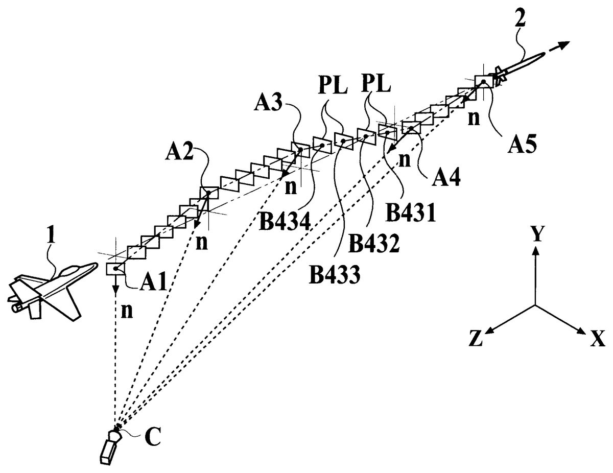
FIGS. 4Ato4C are views showing a state a missile2fired from a fighter plane1controlled by a player flies to a target. While the missile2flies to the target, a posture of the missile2always swings upward, downward, rightward and leftward in a flight direction, in order to take the same posture as one of a real missile. Hereinafter, the fighter plane1will be called a player plane1.
First, positional coordinates of the fired missile2in an object space are determined for every predetermined time, for example, for every frame that is ⅙ second. Second, moving object control data including positional coordinates, speeds and accelerations determined for every predetermined time are stored with a missile identification number of the missile2, as missile control data.
As shown inFIG. 4A, displacement points “A” are generated on a trail of the missile2. The displacement points “A” are generated and determined on the basis of the missile control data determined for every predetermined time. Thereafter, data including displacement point identification numbers, positional coordinates, speeds and accelerations of the displacement points “A”, are stored as displacement point control data. InFIG. 4A, after the missile2was fired, five frames have passed. Therefore, the displacement points “A1” to “A5” are generated on the basis of the missile control data corresponding to the five frames respectively. The reference numerals “A1” to “A5” of the displacement points follow the order of generated displacement points.
As shown inFIG. 4C, the speed “Va” of the displacement point “A” is determined to be a speed composed of a flight directional component “Vt” of the missile2and a substantially vertical directional component “Vr” which is substantially vertical to the flight direction. The direction and the scalar of the substantially vertical directional component “Vr” are determined in accordance with random numbers and so on, at random, and one of factors of representing the swing of the posture of the real missile flying in the sky. Therefore, the displacement points “A1” to “A5” do not keep predetermined positional relationships between each other from the generation to the disappearance, like the smoke of the missile according to an earlier development. The displacement points “A1” to “A5” have speeds directions of which are different from each other and scalars of which are different from each other. Further, because the displacement points “A1” to “A5” move as time passes, the positional relationships between the displacement points “A1” to “A5” changes.
For example, as shown inFIG. 4A, because the positional coordinates of the displacement points “A1” to “A5” are calculated for every predetermined time like the missile2, the line (solid line) connecting the displacement points “A1” to “A5” is different from the trail (two dotted line) of the missile, which is a position when the smoke is emitted.
As shown inFIG. 4B, interpolation points “B” are determined at suitable intervals between displacement points, for example, between the displacement points “A5” and “A4”, the displacement points “A4” and “A3” and so on, in reverse order of reference numerals of the displacement points “A”. For example, between the displacement points “A4” and “A3”, four interpolation points “B431”, “B432”, “B433” and “B434” are determined in this order. Then, quadrilateral polygons are generated and provided as particle system objects, at the displacement points “A” and the interpolation points “B” which are representative points of the quadrilateral polygons. Hereinafter, the quadrilateral polygons will be called smoke polygons “PL”. Thereafter, when each smoke polygon “PL” is regarded as a billboard and the normal vector “n” of each smoke polygon “PL” is turned to a view point “C”, a smoke texture is mapped on each smoke polygon “PL”.
As described above, positions on which the smoke polygons “PL” are provided respectively, are determined on the basis of positions of the displacement points “A”. Thereby, the smoke of the missile, winding as time passes is generated and provided.
Further, suitably, control data is added to the displacement point control data. Therefore, it is possible to represent the smoke of the missile more realistically. For example, a life variable “L” for reducing the displacement points “A” for every frame and a transparency (for example, an a value) determined so as to increase according to the life variable “L” are added to the displacement point control data. Therefore, it is possible to realistically represent the state the smoke clears, diffuses and disappears little by little as time passes.
Further, a predetermined function changing according to the life variable “L” of the displacement point “A” is provided when the smoke polygons “PL” are generated, and the size of the smoke polygon “PL” generated is changed for every frame. Therefore, it is possible to represent the state the smoke is diffused and swept, and to provide an effect as if a wind flowed there.
[Explanation of the Structure]
Next, the structure according to the embodiment of the present invention will be explained with reference toFIG. 5, as follows.
FIG. 5is a view showing an exemplary case the present invention is applied to a consumer game machine1200. As shown inFIG. 5, a player controls a game controller1202or1204, and enjoys playing a fighter plane game or the like, with watching game images displayed on a display1201. In the case, necessary data for playing the game, such as a game program, initial setting data and so on, are stored on a CD-ROM1206, an IC card1208, a memory card1212or the like, as a data storage medium attachable to and detachable from a game apparatus body1210.
[Explanation of the Functional Block]
Next, the functional block which can realize the embodiment of the present invention will be explained with reference toFIGS. 6to9, as follows.
FIG. 6is a block diagram showing an example of the functional block according to the embodiment of the present invention. As shown inFIG. 6, the functional block comprises an input operating unit10, a processing unit20, a display unit30, a storage unit40and a temporary storage unit50.
The input operating unit10outputs game stage data selected by a player, fighter plane data controlled by the player, and so on, to the processing unit20. The input operating unit10has a function which can be realized by hardware such as a lever, buttons and so on.
The processing unit20controls the whole game apparatus, instructs each block of the game apparatus, and processes various types of processing such as a game operation and so on. The processing unit20has a function which can be realized by hardware such as a CPU (CISC type and RISC type), a DSP, an ASIC (gate array and so on) and so on, or software such as a predetermined program (game program).
Further, the processing unit20mainly comprises a game operation unit22for operating processes related to the game and an image generation unit24for generating image data on the basis of various types of data operated by the game operation unit22.
The display unit30outputs image data generates by the image generation unit24to a display screen. The display unit30has a function which can be realized by hardware such as a CRT, a LCD, a HMD and so on.
The storage unit40is realized by hardware such as a CD-ROM, a game cassette, an IC-card. a MO, a flexible disc, a DVD, a memory, a hard disc and so on. The storage unit40stores a game data42including a program for operating processing related to various types of games, a necessary setting data to execute the program, and so on, therein.
The game data42includes various programs and initial setting data.
As the program, the game data42includes a moving object operation program420, a missile control program421, a displacement point determination program422, a displacement point move program423, a particle system object group move program424, and a mapping program425, for performing a moving object operation processing, a missile control processing, a displacement point determination processing, a displacement point move processing, a particle system object group move processing, and a mapping processing, respectively.
As the setting data, the game data42includes an internal coefficient table426used for the particle system object group move processing, and a particle system object group texture427for determining a color and a shape of the smoke.
The temporary storage unit50is a storage area for storing data such as the program, data and so on, used by the processing unit20and another block, therein. The temporary storage unit50has a function which can be realized by hardware such as a RAM and so on. The temporary storage unit50stores a moving object control data51including data related to positional coordinates, a speed, an acceleration and so on of the moving object in the object space, and a displacement point control data table53which is a set of displacement point control data531including data related positional coordinates, speeds, accelerations and so on of the displacement points in the object space. The data related to the missile of the moving object control data51will be called a missile control data511.
[Explanation of the Game Operation Unit]
The game operation unit22performs various game processing on the basis of the operation data outputted from the input operating unit10, the game data42read out from the storage unit40and so on.
The game processing includes, for example, a processing of providing a game selection screen, a processing of modeling an object space, that is, a sky, a water surface, geographical features, buildings and so on, a processing of calculating positions, directions, speeds, accelerations and so on, of a main object such as a fighter plane including the player plane and the target plane and a sub object such as an aircraft carrier, a processing of providing objects in the object space, a processing of selecting mapping data for the objects, a processing of checking hits, a processing of determining results (records), a processing of calculating a position of a view point and an eyes direction, and so on.
Further, the game operation unit22comprises a moving object operation unit220, a missile control unit221, a displacement point determination unit222, a displacement point move unit223and a particle system object group move unit224, as a functional block for performing various processing related to the moving object and the particle system object.
The moving object operation unit220reads the moving object operation program420out from the storage unit40. Then, the moving object operation unit220performs the moving object operation processing of operating a new position, a new speed and so on, on the basis of the moving object control data51and the displacement point control data531. Therefore, the moving object operation unit220carries out the moving object operation processing of moving the moving object in the object space, on the basis of the operation data outputted from the input operation unit10according to the instruction of the player and the predetermined program.
More specifically, the moving object operation unit220calculates new positional coordinates and a new speed on the basis of the control data such as the positional coordinates, the speed, the acceleration of the moving object, at given intervals, for example, for every frame ({fraction (1/60)} second).
In case the position of a moving object of a missile at a “k-1” frame is “Pmk-1”, the speed thereof is “Vmk-1”, the acceleration thereof is “Amk-1”, and the time interval of one frame is “Δt”, the position “Pmk” and the speed “Vmk” of the moving object at a “k” frame are calculated in following equations (1) and (2).
Pmk=Pmk−1+Vmk−1×Δt(1)
Vmk=Vmk−1+Amk−1×Δt(2)
In case the present invention is applied to a game besides the fighter plane game (flight simulator), the moving object may be, for example, a ship, a submarine, a surfboard, a car, a motorcycle, a robot, a character and so on.
The missile control unit221reads the missile control program421out from the storage unit40. Then, the missile control unit221performs the missile control processing of generating and restoring the missile control data511indicating the position, the speed and so on in the object space, of each missile fired from the fighter plane.
More specifically, the missile control data511is stored in the temporary storage unit50, and includes a missile identification number, positional coordinates, a speed, an acceleration and an arrival flag as shown in FIG.7.
When the missile is fired from the fighter plane, the missile control unit221determines a new missile identification number, and generates a new missile control data511. Then, when the missile control unit221outputs the positional coordinates, the speed and the acceleration to the moving object operation unit220for every frame, the moving object operation unit220calculates the new values. Thereafter, the missile control unit221restores the new values as the missile control data511.
For example, as shown inFIG. 7, concerning the missile of the missile identification number “1”, the positional coordinates “Pm1”, the speed “Vm1”, the acceleration “Am1” and the arrival flag “0” are included in the missile control data511-1.
The displacement point determination unit222reads the displacement point determination program422out from the storage unit40. Then, the displacement point determination unit222performs the displacement point determination processing of generating a new displacement point on the trail of the missile and determining data such as the position, the speed and so on of the displacement point, on the basis of the missile control data511. Thereafter, the data such as the position, the speed and so on of the displacement point are stored as the displacement point control data531, in the temporary storage unit50.
More specifically, the displacement point control data531includes a displacement point identification number “an”, positional coordinates, a speed “Van”, an acceleration and a life variable “L” as shown in FIG.8.
The displacement point identification number “an” is “1” when the missile is fired. Further, the displacement point identification number “an” is determined in serial one by one, when the displacement point has already determined.
Coordinates of a periphery of an outlet of a propellant gas of the missile propeller are considered on the basis of the positional coordinates of the fighter plane. The determined coordinates are determined as initial values of the positional coordinates.
The flight directional component “Vtn” of the missile is calculated on the basis of the speed “Vmn” of the missile. Further, the substantially vertical directional component “Vrn” is calculated in accordance with random numbers. Then, the speed “Van” is compounded of the flight directional component “Vtn” and the substantially vertical directional component “Vrn”.
The acceleration may be a coefficient for reducing the speed, or a function related to time. The acceleration is determined according to the type of the particle system object to be represented, as the occasion may demand.
The life variable “L” is suitably determined in order to provide the time from the diffusion to the disappearance of the smoke.
For example, as shown inFIG. 8, concerning the displacement point of the displacement point identification number “3” for a missile, the positional coordinates “Pa3”, the speed “Va3”, the acceleration “Aa1” and the life variable “200” are included in the displacement control data531-3of the displacement point control data table53-1.
Because the displacement points concerning one missile are prepared for every frame, a plurality of displacement points are provided for one missile. Therefore, a plurality of displacement point control data531composes the displacement point control data table53in the temporary storage unit50.
Further, if the life variable “L” is determined according to the environment wherein the game is played, it is possible to represent more realistic game images. That is, in the real world, because most component of the condensation trail or the smoke emitted by the missile is like a water, the time from the generation to the disappearance changes according to a temperature, an atmospheric pressure, and a humidity. Therefore, if the life variable “L” can be determined according to the environment such as a tropical zone, a subtropical zone, a frigid zone, and so on, it is possible to more realistically represent the situation the smoke does not clear up for a long time because the humidity is high.
The displacement point move unit223reads the displacement point move program423out from the storage unit40. Then, the displacement point move unit223performs the displacement point move processing of regenerating a new displacement point control data531of the displacement point which has already generated.
More specifically, the displacement point move unit223reads the displacement point control data531out from the displacement point control data table53one by one, and restores a new displacement point control data531in the displacement point control data table53one by one.
First, the displacement point move unit223subtracts, for example, 1 from the life variable “L”. Next, when determining that the life is left, for example, the life variable “L” is not equal to “0”, the displacement point move unit223outputs the positional coordinates, the speed and the acceleration to the moving object operation unit220. When the moving object operation unit220operates new positional coordinates, a new speed and a new acceleration, the displacement point move unit223obtains the new data and restores a new displacement point control data531in the displacement point control data table53. On the other hand, when determining that the life is not left, for example, the life variable “L” is equal to “0”, the displacement point move unit223deletes the displacement point control data531of the displacement point corresponding to the life variable “L” from the displacement point control data table53.
The particle system object group move unit224reads the particle system object group move program424from the storage unit40. Then, the particle system object group move unit224performs the particle system object group move processing of calculating interpolation points “B” at predetermined intervals between the displacement points “A”, for example, between the displacement points “A5” and “A4”, the displacement points “A4” and “A3”, and so on, in reverse numerical order of the displacement points “A”, and generating the smoke polygons on the basis of the displacement points “A” and the interpolation points
More specifically, for example, in case the particle system object group move unit224generates the smoke polygons between the displacement points “An” and “An-1”, the particle system object group move unit224obtains the positional coordinates of the displacement point “An” and the view point “C”, and calculates the distance from the view point “C” to the displacement point “An”. Then, the particle system object group move unit224refers the interpolation coefficient table426providing the relationship between the distance from the view point “C” to the displacement point “An” and the condition of generating the smoke polygon.
Herein, the interpolation coefficient table426is stored as one of the game data42in the storage unit40. As shown inFIG. 9, the interpolation coefficient table426includes the number of interpolation sheets for determining how many polygon sheets are generated between the displacement points, the interpolation function for determining the positional coordinates at which the polygons are generated between the displacement points and so on, according to the distance from the view point to the displacement point “An”.
The number of interpolation sheets is provided to be smaller in case the distance from the view point is far, and to be larger in case the distance from the view point is near. For example, as shown inFIG. 9, in case the distance “Section 1” is nearer to the view point than the distance “Section 2”, the number of interpolation sheets of the distance “Section 1” is “100” and larger than the number of interpolation sheets of the distance “Section 2” which is “95”. Therefore, concerning the distance “Section 1”, the number of interpolation sheets “100” and the interpolation function “f1(x, y, z)” are included in the interpolation coefficient table426.
Accordingly, because the number of smoke polygons is reduced far from the view point, it is possible to lighten the processing. On the other hand, because the density of smoke polygons is high near to the view point, it is possible to represent more realistic game images.
The interpolation function may be a linear function of interpolating between the displacement points at predetermined intervals. However, the interpolation function is not limited to the linear function. In case the interpolation function is a curvilinear function which is not represented by a linear operation equation, for example, a spline curve, a Bezier curve or the like, because the smoke polygons are generated and provided in a smooth curve along the displacement points, it is possible to represent more realistic game images.
When the particle system object group move unit224refers the number of interpolation sheets and the interpolation function of the interpolation coefficient table426, the particle system object group move unit224determines the interpolation points “Bn” between the displacement points “An” and “An-1”. Then, the particle system object group move unit224provides the smoke polygons so that the representative points of the smoke polygons are the displacement points “An” and “An-1” and the interpolation points “Bn” respectively. When providing the smoke polygons, the particle system object group move unit224performs the smoke polygons as a billboard so that the normal vector of each smoke polygon is turned to the view point. Therefore, even if the smoke polygons are boards, it is possible to represent the smoke polygons so as not to look unnaturally light and bent.
The image generation unit24performs the processing of generating image data according to various data of the operation signal outputted from the input operating unit10, various coordinates and so on. The image generation unit24has a function which can be realized by hardware such as a CPU, a DSP, an image generation IC, a memory and so on. Then, when the image generation unit24outputs the generated image data to the display unit30, the generated image data are displayed on the display unit30. Further, the image generation unit24comprises a mapping unit240for performing a processing of mapping the smoke texture on the smoke polygons on the basis of data outputted from the game operation unit22.
The mapping unit240reads the mapping program425out from the storage unit40, when coordinate data of vertexes of the smoke polygon are inputted from the game operation unit22. Then, the mapping unit240performs a mapping processing of mapping the smoke texture provided in a particle system object group texture427, on the smoke polygons. More specifically, because the particle system object group texture427provides a plurality of textures having different sizes and shading patterns from each other, the mapping unit240selects a texture from the plurality of textures on the basis of the mapping program425, as the occasion may demand, and maps the selected texture on the smoke polygon.
[Explanation of the Flows]
Next, the exemplary processing according to the embodiment of the present invention will be explained in detail, with reference toFIGS. 10to14.
FIG. 10is an exemplary basic flow chart for explaining a processing of generating smoke image data according to the present invention. According to the flow shown inFIG. 10, the game operation unit22performs the processing to the missiles one by one, for every frame.
Hereinafter, each process will be explained in order of firing, flying, arriving and disappearing of the missile, with reference toFIGS. 10to14.
[Processing When the Missile is Fired]
First, the processing when the missile is fired will be explained.
As shown inFIG. 10, first, the missile control unit221performs the missile control processing, to determine the missile control data511such as positions in the object space, a speed and so on of a missile (Step S1).
According to the missile control processing, as shown inFIG. 11, the missile control unit221determines whether the missile is newly fired or not (Step S101). Because the missile is newly fired, when the missile control unit221determines that the missile is newly fired (Step S101; YES), the missile control unit221provides a new missile control data511in the temporary storage unit50, and determines initial values of the missile control data511(Step S102).
When finishing the missile control processing, as shown inFIG. 10, the game operation unit22starts the processing related to the displacement point and the smoke polygon. The game operation unit22reads the missile control data511out from the temporary storage unit50(Step S2). Because the missile is newly fired, when the game operation unit22determines that the missile is newly fired (Step S3; YES), the game operation unit22provides a new displacement point control data table53in the temporary storage unit50(Step S4). Because the displacement point control data table53is provided for each missile, a table identification number may be the same one as the missile identification number.
Next, the displacement point determination unit222performs the displacement point determination processing, to determine a new displacement point. Then, the displacement point determination unit222stores a new displacement point control data531of the determined displacement point, in the displacement point control data table53provided in the Step S4(Step S5).
According to the displacement point determination processing, as shown inFIG. 12, the displacement point determination unit222determines the displacement point identification number “an” to be “1”, because the missile has been just fired (Step S501). Then, the displacement point determination unit222calculates the positional coordinates of the outlet of the missile propellant gas on the basis of the positional coordinates of the missile included in the missile control data511, and determines the positional coordinates of the displacement point on the basis of the positional coordinates of the outlet of the missile propellant gas (Step S502). Then, the displacement point determination unit222calculates the missile flight directional component of the speed of the displacement point, on the basis of the speed of the missile (Step S503). Further, the displacement point determination unit222generates a random number, and calculates the substantially vertical directional component of the speed of the displacement point according to the generated random number (Step S504). Thereafter, the displacement point determination unit222compounds the missile flight directional component and the substantially vertical directional component, to determine the speed of the displacement point (Step S505). Further, the displacement point determination unit222determines the acceleration of reducing the speed of the smoke, as the occasion may demand (Step S506). Then, the displacement point determination unit222stores the determined values in the displacement point control data table53(Step S507), and finishes the displacement point determination processing.
When finishing the displacement point determination processing, as shown inFIG. 10, the particle system object group move unit224starts the particle system object group move processing as shown inFIG. 14(Step S6).
According to the particle system object group move processing, as shown inFIG. 14, the particle system object group move unit224refers the displacement point control data table53in which the determined values are stored in Step S507of theFIG. 12(Step S601). Then, the particle system object group move unit224determines whether the number of displacement points is equal to or more than “2”, or not, on the basis of the displacement point control data table53(Step S602; NO). Because the missile has been just fired, only one displacement point is determined. Therefore, because the particle system object group move unit224determines that the number of displacement points is not equal to or more than “2” (Step S602), and finishes the particle system object group move processing, the smoke polygon is not generated.
When finishing the particle system object group move processing, as shown inFIG. 10, the mapping unit240starts the mapping processing (Step S12). However, because there is not the smoke polygon as an object of mapping, the game operation unit22finishes the basic flow shown in FIG.10.
[Processing While the Missile is Flying]
Next, the processing while the missile is flying will be explained.
As shown inFIG. 10, first, the missile control unit221performs the missile control processing, to determine a new missile control data511including positions in the object space, the speed and so on of the missile (Step S1).
According to the missile control processing, as shown inFIG. 11, because the missile is not newly fired, the missile control unit221determines that the missile is not newly fired (Step S101; NO). Then, because the missile control data511has been already stored in the temporary storage unit50, the missile control unit221reads the stored missile control data511out from the temporary storage unit50and refers the read missile control data511(Step S103). Then, the missile control unit221determines whether the missile has not arrived at a target yet or not (Step S104).
Because the missile is flying, the missile control unit221determines that the missile has not arrived at a target yet (Step S104; YES). Then, the missile control unit221performs the moving object operation program (Step S105), to determine new positional coordinates and a new speed. Thereafter, when the missile control unit221restores a new missile control data511in the temporary storage unit50, the missile control unit221finishes the missile control processing.
When finishing the missile control processing, as shown inFIG. 10, because the missile is not newly fired, the displacement point move unit223performs the displacement point move processing (Steps S2, S3and S7).
According to the displacement point move processing, as shown inFIG. 13, the displacement point move unit223performs the processing of referring the displacement point control data table53which has been already stored in the temporary storage unit50(Step S702), and restoring new control data of displacement points in reverse order of the displacement point identification numbers (Steps S703to S705), to all displacement points stored in the displacement point control data table53(Step S701).
When the displacement point move unit223reads the displacement point control data531of one displacement point from the temporary storage unit50(Step S702), the displacement point move unit223reduces the life variable “L” of the displacement point, and determines whether the life is left or not, on the basis of the life variable “L” (Step S703).
When the displacement point move unit223determines that the life is left, that is, the life variable “L” is not equal to “0” (Step S703; YES), the displacement point move unit223performs the moving object operation processing (Step S704), to determine new positional coordinates and a new speed of the displacement point. Then, when the displacement point move unit223restores a new displacement point control data531including the positional coordinates and the speed in the temporary storage unit50, the displacement point move unit223finishes the displacement point move processing.
On the other hand, when the displacement point move unit223determines that the life is not left, that is, the life variable “L” is equal to “0” (Step S703; NO), because it means that the smoke is diffused and disappears as time passes, the displacement point move unit223deletes the displacement point control data531from the corresponding displacement point control data table53(Step S705), and finishes the displacement point move processing.
When finishing the displacement point move processing, as shown inFIG. 10, the game operation unit22determines whether the missile has arrived at the target or not (Step S8). Because the missile is flying, the game operation unit22determines that the missile has not arrive yet (Step S8; NO). Then, the displacement point determination unit222starts the displacement point determination processing, to determine a new displacement point in order not to break the smoke within the flying distance of the missile, and to store a new displacement point control data531including control data of the new displacement point in the displacement point control data table53(step S5). Then, the particle system object group move unit224performs the particle system object group move processing on the basis of the displacement point control data table53(Step S6).
According to the particle system object group move processing, as shown inFIG. 14, the particle system object group move unit224reads the displacement point control data table53out from the temporary storage unit50(Step S601). Then, the particle system object group move unit224determines whether the number of displacement points is equal to or more than “2” or not, on the basis of the displacement point control data table53(Step S602). Because there are at least two displacement points, when the particle system object group move unit224determines that the number of displacement points is equal to or more than “2” (Step S602; YES), the particle system object group move unit224provides smoke polygons at the displacement points in reverse order of the displacement point identification numbers (Step S603).
First, the particle system object group move unit224obtains positional coordinates of the displacement points “An” and “An-1” and the view point “C” (Step S604), and then calculates the distance from the view point “C” to each of the displacement points “An” and “An-1” (Step S605). Thereafter, the particle system object group move unit224refers the interpolation coefficient table426providing the relationship between the distance from the view point “C” to each displacement point “An” and the condition of generating the smoke polygon, and obtains the number of interpolation sheets and the interpolation function (Step S606).
When referring the number of interpolation sheets and the interpolation function of the interpolation coefficient table426, the particle system object group move unit224calculates coordinates of the interpolation point “Bn” between the displacement points “An” and “An-1” (Step S607). Then, the particle system object group move unit224calculates coordinates of vertexes of smoke polygons so that the coordinates of the displacement point “An” and “An-1” and the interpolation point “Bn” are representative coordinates of the smoke polygons (Step S608). Further, the particle system object group move unit224processes the smoke polygons as a billboard so that a normal vector “n” of each smoke polygon is turned to the view point (Step S609). Therefore, even if the smoke polygon has a board shape, because the smoke polygon is always turned to the view point, the smoke polygon dose not look like unnaturally light or bent.
As described above, when performing the particle system object group move processing to all displacement points “A” in the displacement point control data table53, the particle system object group move unit224finishes the particle system object group move processing.
When finishing the particle system object group move processing, as shown inFIG. 10, the game operation unit22outputs the coordinates of the vertexes of the smoke polygons to the mapping unit240. Then, the mapping unit240maps a particle system object group texture427on the smoke polygons (Step S12).
The particle system object group texture427comprises a plurality of different smoke images from each other, as shown in FIG.22.
Therefore, the mapping unit240selects one of the plurality of smoke images, at random, for every smoke polygon, rotates the selected smoke image, as the occasion may demand, and maps the rotated smoke image on the smoke polygon. Accordingly, even if the smoke polygons continue, the smoke polygons do not look unnatural caused by continuous same textures.
When the mapping unit240finishes the mapping processing, the game operation22finishes the processing of generating the smoke image in the frame.
[Processing When the Missile Arrives]
Next, the processing just after the missile arrives at the target will be explained.
As shown inFIG. 10, the missile control unit221starts the missile control processing. However, because the missile has already disappeared, the missile control unit221performs nothing and finishes the missile control processing (Step S1).
When the missile control unit221finishes the missile control processing, as shown inFIG. 10, because the missile is not newly fired, the displacement point move unit223performs the displacement point move processing (Steps S2, S3and S7).
According to the displacement point move processing, like the above-described processing while the missile is flying, the displacement point move unit223restores new displacement point control data531in reverse order of displacement point identification numbers in the displacement point control data table53(Steps S701to S705; FIG.13).
When the displacement point move unit223finishes the displacement point move processing, as shown inFIG. 10, the game operation unit22determines whether the missile has arrived or not (Step S8). Because the missile has already arrived and disappeared, the game operation unit determines that the missile has arrived and a smoke is not generated (Step S8; YES). Therefore, because the displacement point determination unit222does not perform the displacement point determination processing, the game operation unit determines the number of displacement points (Step S9). Because the missile has just arrived, the game operation unit22determines that the life variables “L” of some displacement points are not equal “0” and the smokes which are not diffused and do not disappear are left. Therefore, the particle system object group move unit224performs the particle system object group move processing (Step S6), and generates smoke polygons. Thereafter, the mapping unit240performs the mapping processing (Step S12), and the game operation unit22finishes the basic flow.
[Processing After the Missile has Disappeared]
Next, the processing of the smoke left after the missile has arrived, been broken and disappeared will be explained.
As shown inFIG. 10, the missile control unit221starts the missile control processing. However, because the missile has already disappeared, the missile control unit221performs nothing and finishes the missile control processing (Step S1). Then, because the missile is not newly fired, the displacement point move unit223performs the displacement point move processing to restore a new displacement point control data531in the displacement point control data table53(Steps S2, S3and S7).
Then, because the missile has arrived, the game operation unit22determines the number of displacement points (Step S8). In case the sufficient time has passed since the missile arrived and disappeared, because the life variables “L” of the displacement points become “0”, the number of displacement points left in the displacement point control data table53decreases. Therefore, in case the number of displacement points is equal to or less than “1”, the game operation unit22determines that it is unnecessary to generate smoke polygons between the displacement points. As a result, the game operation unit22deletes the displacement point control data table53and the missile control data511from the temporary storage unit50(Steps S9to S12).
According to the above-described processing, all the smoke which is left after the missile has arrived and disappeared, disappears. Consequently, it is possible to generate the smoke polygons from the fire to the disappearance of the missile.
FIGS. 23A,23B and23C are views showing exemplary game screens generated according to the above-described processing. The game screens are viewed from a cockpit of the player plane1(shown inFIG. 1) so that the cockpit is the view point “C” (shown in FIG.4B).
InFIG. 23A, two missiles2-1and2-2enter from the left side and the right side to the screen, respectively. Further, the smoke4b-2is represented so as to follow the missile2-2on the screen.
InFIG. 23B, when the more time has passed, two missiles2-1and2-2fly to the center of the screen (in the far direction of the object space). Further, the state is realistically represented on the screen so that the smokes4b-1and4b-2are left in a zigzag line behind the missiles2-1and2-2as time passes.
InFIG. 23C, the state is realistically represented so that the smokes4b-1and4b-2are left in a more zigzag line on the peripheral of the screen as more time passes.
As described above, it is possible to realistically represent the state the particle system object group moves as time passes.
[Structure of Hardware]
Next, an exemplary hardware structure realizable of the embodiment of the present invention will be explained with reference toFIG. 15, as follows.
An apparatus as shown inFIG. 15comprises a CPU1000, a ROM1002, a RAM1004, a data storage medium1006, a sound generation IC1008, an image generation IC1010, and I/O ports1012and1014, that are interconnected by a system bus1016so that data can be exchanged therebetween. A display device1018is further connected to the image generation IC1010, a speaker1020is further connected to the sound generation IC1008, a control device1022is further connected to the I/O port1012, and a communication device1024is further connected to the I/O port1014.
The data storage medium1006corresponds to the storage unit40shown in FIG.6. Further, the data storage medium1006stores primarily programs, image data for representing objects, sound data, play data and so on, and further the game data42shown inFIG. 6, therein.
In case the present invention is realized in a consumer game machine, a CD-ROM, a game cassette, a DVD or other medium is used as the data storage medium for storing game programs and other data, and a memory card or other medium is used as the data storage medium for storing play data. In case the present invention is realized in an arcade game machine, a CD-ROM, a hard disc or other medium is used as the data storage medium. In the case, the data storage medium1006is realized by the ROM1002.
The control device1022corresponds to the input operating unit10shown in FIG.6. Further, the control device1022is equivalent to a game controller, an input operating panel or the like. Therefore, the control device1022is used by a player when the player inputs the decision results while playing the game to the apparatus body.
The CPU1000corresponds to the processing unit20shown in FIG.6. Further, the CPU1000controls the overall of the apparatus and processes various data, according to the programs stored in the data storage medium1006, the system program including initialization data for the apparatus and so on, stored in the ROM1002, signals outputted from the control device1022, or the like.
The RAM1004is a storage means used as an operating memory by the CPU1000, or the like. Further, the RAM1004stores the particular contents of the data storage medium1006or the ROM1002, operating results of the CPU1000, or the like, therein. The RAM1004corresponds to the temporary storage unit50shown in FIG.6.
The sound generation IC1008and the image generation IC1010are also disposed in such a type of game apparatus, to generate and output sounds and images appropriate to the game.
The sound generation IC1008is an integrated circuit for generating game sounds such as sound effects, background music and so on, on the basis of data stored in the data storage medium1006or the ROM1002. The game sounds generated by the sound generation IC1008are outputted from the speaker1020.
The image generation IC1010is an integrated circuit for generating pixel data to be outputted to the display device1018, on the basis of image data outputted from the RAM1004, the ROM1002, the data storage medium1006or the like.
The display device1018corresponds to the display unit30shown in FIG.6. Further, the display device1018can be realized by a CRT, a LCD, a TV, a plasma display, a liquid crystal plasma display, a projector or the like.
The communication device1024is a device for communicating various data used by the game apparatus with an external device. If the game apparatus is connected with another game apparatus, the communication device1024is used for communicating game programs, predetermined data corresponding to game programs, or other data with another game apparatus, through the communications line.
Various processing explained with reference toFIGS. 4to9, are realized by the data storage medium1006which stores programs for executing processing shown in the flow charts of theFIGS. 10to14, and the CPU100, the image generation IC1010, the sound generation IC1008and so on which operate according to the programs. Further, the processing performed by the image generation IC1010, the sound generation IC1018or the like may be performed by the CPU1000, a general DSP or the like, as software.
The present invention can be applied not only to the consumer game machine show inFIG. 4, but also to various apparatuses such as an arcade game machine, a large-sized attraction machine in which a large number of players participate, a simulator, a multimedia terminal, an image generation apparatus, a system board for generating game images and so on.
For example,FIG. 16is a view showing an exemplary case the present invention is applied to an arcade game machine1300.
As shown inFIG. 16, the arcade game machine1300is modeled on a shape of a cockpit of a fighter plane. Therefore, in the arcade game machine1300, a player sitting in a seat1301enjoys piloting a virtual fighter plane by controlling a control stick1303, a slot lever1304and so on, with watching images displayed on a display1302.
Further, the CPU, the image generation IC, the sound generation IC and so on are mounted on a system board1312incorporated in the arcade game machine1300. The game data42is stored in a memory as a data storage medium mounted on the system board1312.
FIG. 17shows an exemplary case the present invention is applied to a game system comprising a host apparatus1400and terminals1404-1to1404-nconnected to the host apparatus1400through a network1402.
InFIG. 17, the game data42is stored in a data storage medium1406, for example, such as a magnetic disk device, a magnetic tape device, a memory and other medium, which can be controlled by the host apparatus1400.
In case each of the terminals1404-1to1404-ncan generate game images and game sounds with standing alone, the host apparatus1400distributes the game program and so on for generating game images and game sounds, to the terminals1404-1to1404-n, through the communication line1402. On the other hand, in case each of the terminals1404-1to1404-ncannot generate game images and game sounds with standing alone, the host apparatus1400generates game images and game sounds, and distributes them to the terminals1404-1to1404-n. Therefore, each terminal outputs the game images and the game sounds.
In case of the structure shown inFIG. 17, means of the present invention may be distributed among and performed by the host apparatus1400and the terminals1404-1and1404-n. Further, the above-described stored data for performing means of the present invention may be distributed among and stored in the host apparatus1400and the terminals1404-1and1404-n.
Further, the terminal connected to the host apparatus1400through the communication line1402may be not only the above-described consumer game machine but also a portable terminal, a portable telephone and so on, such as a personal computer, an arcade game machine, a PDA and so on. In case the arcade game machine is connected to the host apparatus1400through the communication line1402, the terminal may be a portable data storage medium (for example, a memory card and a portable game machine) which can exchange data with the arcade game machine and the consumer game machine.
The present invention has been explained according to the above-described embodiment wherein the present invention is applied to the fighter plane game (flight simulator), and in particular, the smoke image is generated with the trail so as to follow the missile. However, it should also be understood that the present invention is not limited to the embodiment.
Further, the present invention has been explained according to the above-described embodiment wherein the arrangement position of the particle system object group is the displacement point or the interpolation point, the arrangement number of the particle system objects provided at one displacement point or one interpolation point is “1”, and the polygons (smoke polygons) are generated at the displacement point and the interpolation point which are representative points of the polygons. However, it should also be understood that the present invention is not limited to the embodiment and various changes and modifications may be made to the invention without departing from the gist thereof.
For example,FIGS. 18A and 18Bare views showing the state the present invention is applied to the case the fighter plane (moving object) makes a steep descent for a water surface and flies on just the water surface. Herein, the present invention is applied to the image generation of bubbles generated when waves have risen on the water surface according to the pressure change caused by the fighter plane. The polygons are provided on the water surface along the trail of the fighter plane, and the bubble texture is mapped on each polygon. Thereby, the bubbles are represented.
More specifically, as shown inFIG. 18A, the displacement point determination unit222determines the displacement points “A” like the above-described embodiment. In case some of the displacement points “A” are provided within a predetermined distance from the water surface, as shown inFIG. 18B, the displacement point determination unit222projects the displacement points “A” which are provided within the predetermined distance, on the water surface, and calculates coordinates of the projected displacement points “A′”.
Each projected displacement point “A″” has a speed composed of random directional speed components along the water surface. The random directional speed components correspond to the missile flight directional speed component and the substantially vertical directional speed component which represent the flow of the wind and so on according to the above-described embodiment, and represent factors externally influencing the bubbles, such as a fluctuation of the water surface, a current of a tide and so on.
When the particle system object group move unit224calculates coordinates of interpolation points “B” on the basis of the projected displacement points “A′”, the particle system object groups are generated and provided at the projected displacement points “A′” and the interpolation points “B”.
The particle system object group move unit224determines the number of particle system object groups or particle system objects (bubble polygons) constituting the particle system object group, the size of the particle system object group at the initial arrangement and so on, according to the speed and the altitude from the water surface of the fighter plane.
For example, at the position of the projected displacement point “A′3” as shown inFIG. 18B, because of the steep descent, the fighter plane flies at highest speed and at the lowest altitude. Therefore, two substantially circular particle system object groups PG31and PG32are provided at the same time. Accordingly, because large quantities of bubbles are generated, it is possible to represent a power of the steep descent realistically.
Further, at the position of the projected displacement points “A′4” to “A′6”, because the fighter plane1flies at stable speed and at the stable altitude, the particle system object groups including the almost same number of polygons are provided.
Further, the particle system object group move unit224enlarges the size of the particle system object group provided on the water surface as time passes. Therefore, it is possible to realistically represent as if the bubbles were diffused. In the case, for example, a plurality of polygons constituting the particle system object group are provided so as to separate from the center as time passes, and the size of each polygon is enlarged as time passes.
Furthermore, in case the displacement point control data531further includes a transparency, the transparency may increase as time passes, for example, according to an α value. In the case, it is possible to represent the bubbles disappearing little by little.
FIGS. 19A and 19Bare views showing exemplary game screens generated as described above. InFIGS. 19A and 19B, bubbles5are represented realistically behind the fighter plane1.
As another example, as shown inFIG. 20A, the present invention may be applied to a motor boat6sailing on the water surface and stern waves.
In case the moving object is the motor boat6, the displacement point determination unit222generates the displacement pints “A” on the sailing course of the motor boat6on the water surface. Then, the displacement point determination unit222determines auxiliary displacement points “AR” and “AL” at right and left sides of the displacement points “A” in the sailing direction of the motor boat6. The displacement points “A” and the auxiliary displacement points “AR” and “AL” have speeds composed of random directional speed components in the direction of the water surface. In particular, the auxiliary displacement points “AR” and “AL” have accelerations in a substantially right direction and a substantially left direction to the sailing direction, respectively.
The displacement point move unit223moves the displacement points “A” and the auxiliary displacement points “AR” and “AL” as time passes. Then, when the particle system object group move unit224determines interpolation points “B”, “BR” and “BL” which are not shown inFIG. 20A, on the basis of the moved displacement points “A” and the moved auxiliary displacement points “AR” and “AL”, respectively, the particle system object group move unit224provides bubble polygons at the determined points. Thereafter, the mapping unit240maps bubble textures of stern waves shown inFIG. 20Bon the bubble polygons.
Therefore, it is possible to generate images of realistic stern waves which expand in a zigzag line rightward and leftward as time passes.
Further, because the particle system object group at the displacement point “A” expands as time passes, it is possible to realistically represent the state a large number of bubbles included in the central stern wave rise as time passes and the water surface becomes white.
Furthermore, the present invention can be applied not only to the fighter plane game (flight simulator) but also to various games, for example, a game of a plane except the fighter plane, a space ship game, a racing game, an action game, a robot versus fighting game, a sports game, a shooting game, a role playing game and so on.
For example, as shown inFIG. 21, the present invention can be applied to a role playing game wherein when a girl character7waves a magic wand8, stars are generated so as to have a lasting twinkling effect from a top of the magic wand8.
In the above-described case, like the smoke of the missile, the displacement point determination unit222determines the displacement points “A” which are not shown inFIG. 21, on the course of the top of the magic wand8. Then, the particle system object group move unit224determines the interpolation points “B” which are not shown inFIG. 21, on the basis of the displacement points “A”. Thereafter, when the particle system object group move unit224provides star polygons at the displacement points “A” and the interpolation points “B”, the mapping unit240maps star textures on the star polygons.
Herein, the displacement point determination unit222further provides a brightness variable in the displacement point control data531. Then, the particle system object group move unit224interpolates brightness variables of the interpolation points “B” on the basis of brightness variables of the displacement points “A”, like the case of interpolating positions of the interpolation points “B” on the basis of positions of the displacement points “A”. Therefore, the particle system object group move unit224provides the brightness to each of polygons at the displacement points “A” and the interpolation points “B”.
Therefore, it is possible not only to generate and provide star polygons so as to follow the magic wand8, but also to further provide a fantastic representation wherein the brightness of the star polygons is smoothly changed between the displacement points “A”. Further, if the brightness variable is determined as a curve function of time (for example, a sine function, a Lissajou function and so on), it is possible to provide a more fantastic representation wherein the brightness of the star polygons is changed so as to wave in turn as time passes.
According to the present invention, the following effects will be indicated.
To generate image data of the particle system object group such as a cloud, a smoke, bubbles and so on, the displacement point is provided as a representative point indicating the position to which the particle system object group is moved, and moved on the basis of a random movement of a wind, a particle system object generation source or the like, as time passes. Then, the particle system object group is provided in the object space, on the basis of the position of the moved displacement point. Accordingly, it is possible to provide the particle system object group as if the particle system object group were moved on the basis of the random movement of the wind, the particle system object generation source or the like, as time passes.
Further, because only the displacement point is moved at predetermined time intervals, it is possible to generate realistic image data of a condensation trail waving in a wind, a smoke in a muddle by a rafter or the like, according to a large number of particle system objects, only in a light operation load and a little used storage capacity.
Further, because the displacement point represents not only the position of the particle system object group but also the transparency, the brightness and so on of the particle system object group as the occasion may demand, it is possible to further provide various effects of diffusing or flickering the particle system object as time passes.
Furthermore, because the number or the size of the particle system object groups, or the number or the position of the particle system objects constituting the particle system object group is changed as the occasion may demand, it is possible to represent the particle system object group in various ways and to generate more realistic image data.
The entire disclosure of Japanese Patent Application No. Tokugan 2001-94376 filed on Mar. 28, 2001 including specification, claims, drawings and summary are incorporated herein by reference in its entirety.
Claims
- A method for generating image data of a virtual space viewed from a predetermined view point, comprising: providing a particle system object group comprising at least one particle system object which includes a plurality of particles in the virtual space, according to a predetermined rule, continuously or intermittently;determining a displacement point as a basis for moving the provided particle system object group, in the virtual space;moving the determined displacement point in a predetermined direction as time passes;and moving the provided particle system object group on the basis of the moved displacement point.
- The method as claimed in claim 1 , further comprising: providing the particle system object group so as to attach to or follow a moving object moving in the virtual space.
- The method as claimed in claim 2 , further comprising: determining the displacement point on the basis of a position of the moving object at predetermined time intervals.
- The method as claimed in claim 2 , further comprising: determining the predetermined direction to be at least a substantially vertical direction to a moving direction of the moving object at the displacement point, to move the displacement point in the predetermined direction.
- The method as claimed in claim 2 , further comprising: changing at least one of providing one particle system object group or a predetermined number of particle system object groups, a size of the particle system object group, and a transparency of the particle system object group, on the basis of at least one of a position, a moving speed, a moving direction and a type of the moving object, to provide the particle system object group or the predetermined number of particle system object groups.
- The method as claimed in claim 2 , further comprising: changing at least one of providing the particle system object group comprising one particle system object or a predetermined number of particle system objects, a position of the particle system object, a size of the particle system object, and a transparency of the particle system object, on the basis of at least one of a position, a moving speed, a moving direction and a type of the moving object, to provide the particle system object group.
- The method as claimed in claim 2 , further comprising: changing at least one of the predetermined direction and a moving speed of the displacement point, on the basis of at least one of a moving speed, a moving direction, a movement and a type of the moving object, to move the displacement point.
- The method as claimed in claim 2 , further comprising: moving the particle system object group on the basis of the displacement point, according to a moving direction of the moving object.
- The method as claimed in claim 1 , further comprising: changing at least one of a size and a transparency of the particle system object group as time passes.
- The method as claimed in claim 1 , further comprising: changing at least one of a position, a size and a transparency of the particle system object of the particle system object group as time passes.
- The method as claimed in claim 1 , further comprising: turning the particle system object which is formed in a board, in a predetermined direction based on the predetermined view point.
- An apparatus adapted to carry out the method as claimed in claim 1 .
- The apparatus as claimed in claim 12 , further comprising a game execution unit for executing a predetermined game according to the image data generated.
- A storage medium having a program recorded thereon, when the program is loaded onto an operating apparatus, the program making the operating apparatus execute the method as claimed in claim 1 .
- A program, when the program is loaded onto an operating apparatus, to make the operating apparatus execute the method as claimed in claim 1 .
- A program product comprising a storage medium having a program recorded thereon, when the program is loaded onto an operating apparatus, the program making the operating apparatus execute the method as claimed in claim 1 .
- A method for generating image data of a virtual space viewed from a predetermined view point, comprising: providing a particle system object group representing a particle system of a cloud, so as to attach to or follow a moving object moving in the virtual space, continuously or intermittently;changing a position of the provided particle system object group as time passes;and stopping representing the particle system object group or deleting the particle system object group among the provided particle system object group including the particle system object group of which position is changed, when the particle system object group is provided for a predetermined time.
- An apparatus adapted to carry out the method as claimed in claim 17 .
- The apparatus as claimed in claim 18 , further comprising a game execution unit for executing a predetermined game according to the image data generated.
- A storage medium having a program recorded thereon, when the program is loaded onto an operating apparatus, the program making the operating apparatus execute the method as claimed in claim 17 .
- A program, when the program is loaded onto an operating apparatus, to make the operating apparatus execute the method as claimed in claim 17 .
- A program product comprising a storage medium having a program recorded thereon, when the program is loaded onto an operating apparatus, the program making the operating apparatus execute the method as claimed in claim 17 .
- A method for generating image data of a virtual space viewed from a predetermined view point, comprising: providing a particle system object group representing a particle system of a cloud or a bubble, so as to attach to or follow a moving object moving in the virtual space, continuously or intermittently;and moving the provided particle system object group in a moving direction at a moving speed, as time passes, while changing at least one of the moving direction and the moving speed of the provided particle system object group according to a movement of the moving object.
- An apparatus adapted to carry out the method as claimed in claim 23 .
- The apparatus as claimed in claim 24 , further comprising a game execution unit for executing a predetermined game according to the image data generated.
- A storage medium having a program recorded thereon, when the program is loaded onto an operating apparatus, the program making the operating apparatus execute the method as claimed in claim 23 .
- A program, when the program is loaded onto an operating apparatus, to make the operating apparatus execute the method as claimed in claim 23 .
- A program product comprising a storage medium having a program recorded thereon, when the program is loaded onto an operating apparatus, the program making the operating apparatus execute the method as claimed in claim 23 .
- A method for generating image data of a virtual space viewed from a predetermined view point, comprising: providing a particle system object group representing a particle system of a bubble, so as to attach to or follow a moving object moving in the virtual space, continuously or intermittently;changing a position of the provided particle system object group as time passes;and stopping representing the particle system object group or deleting the particle system object group among the provided particle system object group including the particle system object group of which position is changed, when the particle system object group is provided for a predetermined time.
- An apparatus adapted to carry out the method as claimed in claim 29 .
- The apparatus as claimed in claim 30 , further comprising a game execution unit for executing a predetermined game according to the image data generated.
- A storage medium having a program recorded thereon, when the program is loaded onto an operating apparatus, the program making the operating apparatus execute the method as claimed in claim 29 .
- A program, when the program is loaded onto an operating apparatus, to make the operating apparatus execute the method as claimed in claim 29 .
- A program product comprising a storage medium having a program recorded thereon, when the program is loaded onto an operating apparatus, the program making the operating apparatus execute the method as claimed in claim 29 .
- A method for generating image data of a virtual space viewed from a predetermined view point, comprising: providing a particle system object group comprising at least one particle system object which includes a plurality of particles in the virtual space, according to a predetermined rule, continuously or intermittently;determining a displacement point as a basis for moving the provided particle system object group, in the virtual space;moving the determined displacement point in a predetermined direction as time passes;moving the provided particle system object group on the basis of the moved displacement point;and changing a size of each provided particle system object group and diffusing the provided particle system object group of which size is changed as time passes.
- The method as claimed in claim 35 , further comprising: providing the particle system object group so as to attach to or follow a moving object moving in the virtual space.
- The method as claimed in claim 36 , further comprising: determining the displacement point on the basis of a position of the moving object at predetermined time intervals.
- The method as claimed in claim 36 , further comprising: determining the predetermined direction to be at least a substantially vertical direction to a moving direction of the moving object at the displacement point, to move the displacement point in the predetermined direction.
- The method as claimed in claim 36 , further comprising: changing at least one of providing one particle system object group or a predetermined number of particle system object groups, a size of the particle system object group, and a transparency of the particle system object group, on the basis of at least one of a position, a moving speed, a moving direction and a type of the moving object, to provide the particle system object group or the predetermined number of particle system object groups.
- The method as claimed in claim 36 , further comprising: changing at least one of providing the particle system object group comprising one particle system object or a predetermined number of particle system objects, a position of the particle system object, a size of the particle system object, and a transparency of the particle system object, on the basis of at least one of a position, a moving speed, a moving direction and a type of the moving object, to provide the particle system object group.
- The method as claimed in claim 36 , further comprising: changing at least one of the predetermined direction and a moving speed of the displacement point, on the basis of at least one of a moving speed, a moving direction, a movement and a type of the moving object, to move the displacement point.
- The method as claimed in claim 36 , further comprising: moving the particle system object group on the basis of the displacement point, according to a moving direction of the moving object.
- The method as claimed in claim 35 , further comprising: changing a transparency of the particle system object group as time passes.
- The method as claimed in claim 35 , further comprising: changing at least one of a position, a size and a transparency of the particle system object of the particle system object group as time passes.
- The method as claimed in claim 35 , further comprising: turning the particle system object which is formed in a board, in a predetermined direction based on the predetermined view point.
- An apparatus adapted to carry out the method as claimed in claim 35 .
- The apparatus as claimed in claim 46 , further comprising a game execution unit for executing a predetermined game according to the image data generated.
- A storage medium having a program recorded thereon, when the program is loaded onto an operating apparatus, the program making the operating apparatus execute the method as claimed in claim 35 .
- A program, when the program is loaded onto an operating apparatus, to make the operating apparatus execute the method as claimed in claim 35 .
- A program product comprising a storage medium having a program recorded thereon, when the program is loaded onto an operating apparatus, the program making the operating apparatus execute the method as claimed in claim 35 .
Disclaimer: Data collected from the USPTO and may be malformed, incomplete, and/or otherwise inaccurate.