U.S. Pat. No. 6,881,149
ENTERTAINMENT SYSTEM, ENTERTAINMENT APPARATUS, RECORDING MEDIUM, AND PROGRAM
AssigneeSony
Issue DateJuly 25, 2002
U.S. Patent No. 6,881,149: Entertainment system, entertainment apparatus, recording medium, and program

Summary:
The ‘149 patent describes a method used in video games where the main character can easily identify and target enemy characters. The invention calls for a rectangular navigation mark which is displayed over a designated monster on the screen. Whenever the main character approaches the enemy, the navigation mark signals that the player is close and begins emitting a light which draws the player’s attention to it. This invention should make the game easier by assisting the player in finding enemies to battle. Once the player has located the enemy he can then target the enemy and press buttons which will correspondingly produce an attack on the enemy.
Abstract:
When a main character enters a battle, a rectangular navigation mark is displayed over a designated monster on a display monitor. When the main character approaches the monster, the navigation mark rotates and gets smaller until it is converged into a targeting point on the display monitor. When the navigation mark is converged into a targeting point, light is emitted from the navigation mark on the display monitor. An additional attack of the main character can be performed against the monster if a user presses a decision button at the best timing, right when the light is emitted from the navigation mark.
Illustrative Claim:
1. An entertainment system comprising: an entertainment apparatus for executing various programs; at least one manual controller for inputting a manual control request of a user to said entertainment apparatus; and a display monitor for displaying an image outputted from said entertainment apparatus, said entertainment apparatus comprising: means for performing a first process of moving a navigation mark displayed on said display monitor in a predetermined direction as time advances; means for performing a second process of calculating a time difference between a point of time when said navigation mark reached a predetermined position and a point of time when said user inputted manipulation data via said manual controller; and means for generating an event and successively repeating said first process and said second process if the time difference is within a predetermined time, wherein said event is generated for changing a parameter of a single character.
Illustrative Figure
Abstract
When a main character enters a battle, a rectangular navigation mark is displayed over a designated monster on a display monitor. When the main character approaches the monster, the navigation mark rotates and gets smaller until it is converged into a targeting point on the display monitor. When the navigation mark is converged into a targeting point, light is emitted from the navigation mark on the display monitor. An additional attack of the main character can be performed against the monster if a user presses a decision button at the best timing, right when the light is emitted from the navigation mark.
Description
DESCRIPTION OF THE PREFERRED EMBODIMENT An embodiment of the entertainment system according to the present invention which is applied to a video game apparatus, and an embodiment of the recording medium according to the present invention which is applied to a recording medium for storing a program and data executable by the video game apparatus will be described with reference toFIGS. 1 through 27. As shown inFIG. 1, an entertainment system10basically comprises an entertainment apparatus12for executing various programs, a memory card14detachably connected to the entertainment apparatus12, a manual controller16detachably connected to the entertainment apparatus12by a connector62, and a display monitor18such as a television receiver which is supplied with video and audio output signals from the entertainment apparatus12. The entertainment apparatus12reads a program recorded in a mass storage medium such as an optical disk20such as a CD-ROM or the like, and executes a game, for example, based on the program depending on commands supplied from a user, e.g., a game player, via the manual controller16. The execution of the game mainly represents controlling the progress of the game by controlling the display of images and the generation of sounds on the display monitor18based on manual input actions entered from the manual controller16via the connector62. The entertainment apparatus12has a substantially flat casing in the shape of a rectangular parallelepiped which houses a disk loading unit22disposed centrally for loading an optical disk20for supplying an application program and data for a video game or the like. The casing supports a reset switch24for resetting a program which is being presently executed, a disk control switch26for controlling the loading of the optical disk20, a power supply switch28, and two slots30,32. The entertainment apparatus12may be supplied with the application program via a communication link, rather than being supplied from the optical disk20as the recording medium. The slots30,32have ...
DESCRIPTION OF THE PREFERRED EMBODIMENT
An embodiment of the entertainment system according to the present invention which is applied to a video game apparatus, and an embodiment of the recording medium according to the present invention which is applied to a recording medium for storing a program and data executable by the video game apparatus will be described with reference toFIGS. 1 through 27.
As shown inFIG. 1, an entertainment system10basically comprises an entertainment apparatus12for executing various programs, a memory card14detachably connected to the entertainment apparatus12, a manual controller16detachably connected to the entertainment apparatus12by a connector62, and a display monitor18such as a television receiver which is supplied with video and audio output signals from the entertainment apparatus12.
The entertainment apparatus12reads a program recorded in a mass storage medium such as an optical disk20such as a CD-ROM or the like, and executes a game, for example, based on the program depending on commands supplied from a user, e.g., a game player, via the manual controller16. The execution of the game mainly represents controlling the progress of the game by controlling the display of images and the generation of sounds on the display monitor18based on manual input actions entered from the manual controller16via the connector62.
The entertainment apparatus12has a substantially flat casing in the shape of a rectangular parallelepiped which houses a disk loading unit22disposed centrally for loading an optical disk20for supplying an application program and data for a video game or the like. The casing supports a reset switch24for resetting a program which is being presently executed, a disk control switch26for controlling the loading of the optical disk20, a power supply switch28, and two slots30,32.
The entertainment apparatus12may be supplied with the application program via a communication link, rather than being supplied from the optical disk20as the recording medium.
The slots30,32have respective upper slot units30B,32B and respective lower slots units30A,32A. Two manual controllers16may be connected respectively to the lower slots units30A,32A, and memory cards14(or unillustrated portable information terminals having the function of the memory card14) for storing flags indicative of interim game data may be connected respectively to the upper slots units30B,32B. The slots30,32(the upper slot units30B,32B and the lower slots units30A,32A) are asymmetrically shaped to prevent the connectors62and the memory cards14from being inserted in the wrong direction.
As shown inFIGS. 2 and 3, the manual controller16has first and second control pads34,36, an L (Left) button38L, an R (Right) button38R, a start button40, and a selection button42. The manual controller16also has joysticks44,46for inputting analog control actions, a mode selection switch48for selecting control modes of the joysticks44,46, and an indicator50for indicating a selected control mode. The indicator50comprises a light-emitting element such as a light-emitting diode or the like.
As shown inFIG. 2, the manual controller16has a housing104comprising an upper member100and a lower member102which are mated and joined to each other by fasteners such as screws.
As shown inFIGS. 2 and 3, a pair of left and right grips106,108projects from one side of respective opposite ends of the housing104. The left and right grips106,108are shaped so as to be gripped by the palms of left and right hands of the user or game player when the manual controller16is connected to the entertainment apparatus12and information retrieval is carried out or the game is played thereby, for example.
As shown inFIG. 3, the left and right grips106,108are progressively spaced away from each other toward their distal ends. To allow the game player to grip the left and right grips106,108comfortably for a long period of time, the left and right grips106,108are tapered from their joint with the housing104toward their distal ends, and have arcuate outer peripheral surfaces and arcuate distal end surfaces.
As shown inFIGS. 2 and 3, the first control pad34is disposed on one end of the housing104and comprises a first pressable control member (up button)110a, a second pressable control member (right button)110b, a third pressable control member (down button)110c, and a fourth pressable control member (right button)110d. The first through fourth pressable control members110a,110b,110c,110d, project on an upper surface of the housing104and are arranged in a crisscross pattern.
The first control pad34includes switch elements as signal input elements associated respectively with the first through fourth pressable control members110a,110b,110c,110d. The first control pad34functions as a directional controller for controlling the direction of movement of a displayed game character, for example. When the game player selectively presses the first through fourth pressable control members110a,110b,110c,110dto turn on or off the switch elements associated respectively with the first through fourth pressable control members110a,110b,110c,110d, the displayed game character moves in the direction corresponding to the pressed one of the first through fourth pressable control members110a,110b,110c,110d.
As shown inFIGS. 2 and 3, the second control pad36is disposed on the other end of the housing104and comprises a first pressable control member (Δ button)112a, a second pressable control member (□ button)112b, a third pressable control member (x button)112c, and a fourth pressable control member (∘ button)112d. The first through fourth pressable control members112a,112b,112c,112dproject on the upper surface of the housing104and are arranged in a crisscross pattern.
The first through fourth pressable control members112a,112b,112c,112dare constructed as independent members, and associated with respective switch elements disposed in the second control pad36.
The second control pad36serves as a function setting/performing unit for setting functions for a displayed game character assigned to the pressable control members112a-112dor performing functions of a displayed game character when the switch elements associated with the pressable control members112a-112dare turned on.
The L button38L and the R button38R are disposed on a side of the housing104remote from the left and right grips106,108and positioned respectively at the opposite ends of the housing104. As shown inFIGS. 2 and 4, the L button38L has a first left pressable control member (L1button)114aand a second left pressable control member (L2button)114b, and the R button38R has a first right pressable control member (R1button)116aand second right pressable control member (R2button)116b, respectively. The L button38L and the R button38R have respective switch elements associated respectively with the pressable control members (the L1button114a, the L2button114b, the R1button116a, and the R2button116b).
The L button38L and the R button38R serve as respective function setting/performing units for setting functions for a displayed game character assigned to the pressable control members114a,114band116a,116bor performing functions of a displayed game character when the switch elements associated with the pressable control members114a,114band116a,116bare turned on.
As shown inFIGS. 2 and 3, the manual controller16also has first and second analog control pads118,120disposed respectively at confronting corners defined between the housing104and the proximal ends of the left and right grips106,108which are joined to the housing104.
The first and second analog control pads118,120have the respective joysticks44,46which can be tilted in all directions (360°) about control shafts thereof, and respective signal input elements such as variable resistors or the like which are operable by the respective joysticks44,46. Specifically, the control shaft of the left and right joysticks44,46are normally urged to return to their neutral positions by biasing members. The left and the right joysticks44,46can be freely tilted in all directions (360°) about the axes of the control shafts.
The first and second analog control pads118,120can move a displayed game character while rotating the same or while changing its speed, and can make an analog-like action such as to change the form of a displayed character, when the game player manipulates the joysticks44,46. Therefore, the first and second analog control pads118,120are used as a control unit for entering command signals for a displayed character to perform the above movement or action.
When the mode selection switch48is pressed, it can select a control mode for allowing a command signal to be inputted from the first and second analog control pads118,120or a control mode for inhibiting a command signal from being inputted from the first and second analog control pads118,120.
When the mode selection switch48is pressed, it can also select a control mode for allowing a command signal to be inputted from the first and second analog control pads118,120and selecting the function of the first through fourth pressable control members112a,112b,112c,112dof the second control pad36or the function of the pressable control members114a,114band116a,116bof the L button38L and the R button38R. Depending on the control mode selected by the mode selection switch48, the mode indicator50flickers and changes its indication light.
As shown inFIG. 4, the left and right grips106,108projecting from the housing104are gripped respectively by the palms of the hands of the game player. The housing104is not required to be supported by fingers, and the manual controller16can be held by the hands while at least six out of the ten fingers of the hands can freely be moved.
As shown inFIG. 4, when the first and second grips106,108are gripped respectively by the palms of the hands of the game player, the thumbs Lf1, Rf1of the left and right hands can extend over the joysticks44,46of the first and second analog control pads118,120, the first through fourth pressable control members110a-110dof the first control pad34, and the first through fourth pressable control members112a-112dof the second control pad36, and can selectively press the joysticks44,46, the pressable control members110a-110d, and the pressable control members112a-112d.
Since the joysticks44,46of the first and second analog control pads118,120are positioned in confronting relation to the proximal ends of the left and right grips106,108which are joined to the housing104, when the left and right grips106,108are gripped by the left and right hands, the joysticks44,46are positioned most closely to the thumbs Lf1, Rf1, respectively. Therefore, the joysticks44,46can easily be manipulated by the thumbs Lf1, Rf1.
As shown inFIG. 4, when the left and right grips106,108are gripped respectively by the palms of the hands of the game player, the index fingers Lf2, Rf2and middle fingers Lf3, Rf3of the left and right hands can extend over positions where they can selectively press the L1button114a, L2button114bof the L button38L and R1button116a, R2button116bof the R button38R.
As shown inFIG. 5, the manual controller16has a pair of vibration imparting mechanisms128L,128R for imparting vibrations to the user in order for the user to be able to play a highly realistic game.
As shown inFIG. 5, the left and right vibration imparting mechanisms128L,128R are positioned near the proximal ends of the left and right grips106,108that are held by the hands and fingers when the manual controller16is gripped by the user.
Since the both vibration imparting mechanisms128L,128R have basically the same structure except their vibration characteristics, only the right vibration imparting mechanism128R will be described for the purpose of brevity.
The vibration imparting mechanisms128R comprises a motor130R energizable by a vibration generating command supplied from the entertainment apparatus12, and an eccentric member134R mounted eccentrically on the drive shaft of the motor130R.
The eccentric member134R comprises a weight in the form of a heavy metal member having a semicircular cross-sectional shape. The weight has an off-center hole defined therein in which the drive shaft of the motor130R is fitted.
According to the vibration imparting mechanisms128L,128R as constructed above, when the motors130L,130R are energized, the drive shafts thereof rotate to cause the eccentric members134L,134R to rotate in an eccentric motion for thereby generating vibrations, which are imparted to the left grip106and the right grip108. Then, the vibrations of the left grip106and the right grip108are applied to the hands and fingers of the user.
Next, the vibration characteristics of the vibration imparting mechanisms128L,128R disposed in the left grip106and the right grip108respectively will be described hereinbelow.
The vibration imparting mechanisms128L,128R have the different vibration characteristics.
For example, the motor130L of the left vibration imparting mechanism128L is bigger than the motor130R of the right vibration mechanism128R. The rotational speed of the motor130L varies according to a vibration value included in a vibration generating command transmitted from the entertainment apparatus12. That is, vibrations having different frequencies can be generated depending on the vibration value. In the present embodiment, the vibration frequency of the motor130L varies in proportion to the vibration value.
In contrast to the motor130L of the left vibration mechanism128L, the vibration frequency of the motor130R of the right vibration mechanism128R does not vary according to the vibration value included in the vibration generating command. The motor130R of the right vibration mechanism128R is simply energized or deenergized according to the vibration value. If the vibration value (logic value) is “1”, the motor130R of the right vibration mechanism128R is energized. If the vibration value is “0”, the motor130R of the right vibration mechanism128R is deenergized. When the motor130R of the right vibration mechanism128R is energized, it rotates at a constant speed to generate vibrations at a constant frequency.
In order to energize the motors130L,130R to vibrate the manual controller16in its entirety, a bidirectional communication function needs to be provided between the manual controller16and the entertainment apparatus12. This bidirectional communication function will be described later on.
Next, circuit arrangements of the entertainment apparatus12and the manual controller16will be described below with reference toFIGS. 6 through 8.
As shown inFIG. 6, the entertainment apparatus12comprises a control system82including a central processing unit (CPU)80and peripheral devices thereof, a graphic system84including a frame buffer (not illustrated) and a graphic processing unit (GPU) for rendering image data in the frame buffer, a sound system86including a sound processing unit (SPU) for generating music sounds and sound effects, an optical disk controller88for controlling the readout of the optical disk20in which application programs and data are stored, a communication controller90for controlling the inputting of data into and outputting of data from the manual controller16and the memory card14, and a system bus92to which the control system82, the graphic system84, the sound system86, the optical disk controller88, and the communication controller90are connected.
Video and audio signals generated by and outputted from the graphic system84and the sound system86are supplied to the display monitor18to display images on the monitor screen of the display monitor18and reproduce sounds from the speakers of the display monitor18.
As shown inFIG. 7, the manual controller16comprises a communication controller150, a CPU152, a program memory154, a working RAM156, a digital input block158, an analog input block160, the left motor driver170L, the left motor130L, the right motor driver170R, and the right motor130R. These components of the manual controller16are connected to a bus162.
The digital input block158functions as a manual input controller for the first through fourth pressable control members110a-110dof the first control pad34and the first through fourth pressable control members112a-112dof the second control pad36. The analog input block160functions as a manual input controller for the left and right joysticks44,46. The digital input block158and the analog input block160allow the user to enter various items of information into the manual controller16.
The communication controller150has a function to effect serial communications with an external device. The communication controller150is electrically connectable to the communication controller90of the entertainment apparatus12(see FIG.6), for example, for data communication with the entertainment apparatus12.
As shown inFIG. 8, the bidirectional communication function between the entertainment apparatus12and the manual controller16can be performed when the connector62capable of performing bidirectional serial communications with the manual controller16is connected to the entertainment apparatus12.
A system in the manual controller16for performing the bidirectional communication function comprises a serial I/O interface SIO for performing serial communication with the entertainment apparatus12, a parallel I/O interface PIO for entering manipulation data from a plurality of control buttons, a one-chip microcomputer comprising a CPU, a RAM, and a ROM, and motor drivers170R,170L for energizing the motors130R,130L of the vibration imparting mechanisms128R,128L. The motors130R,130L are energized for rotation by voltages and currents supplied from the corresponding motor drivers170R,170L.
A system in the entertainment apparatus12for performing the bidirectional communication function comprises a serial I/O interface SIO for performing serial communication with the manual controller16. When the connector62is connected to the serial I/O interface SIO of the entertainment apparatus12, the serial I/O interface SIO of the entertainment apparatus12is connected to the serial I/O interface SIO of the manual controller16via the connector62for performing bidirectional communications between the manual controller16and the entertainment apparatus12. Other structural details of the entertainment apparatus12are omitted from illustration in FIG.8.
Signal and control lines for bidirectional serial communications include a data transfer signal line TXD (Transmit X′ for Data) for sending data from the entertainment apparatus12to the manual controller16, a data transfer signal line RXD (Received X′ for Data) for sending data from the manual controller16to the entertainment apparatus12, a serial synchronous clock signal line SCK (Serial Clock) for extracting data from the data transfer signal lines TXD, RXD, a control line DTR (Data Terminal Ready) for establishing and cutting off communication with the manual controller16as a terminal, and a flow control line DSR (Data Set Ready) for transferring a large amount of data.
The signal and control lines for bidirectional serial communication are accommodated in a cable. As shown inFIG. 8, this cable further includes a power line172extending from a power supply in the entertainment apparatus12and connected to the motor drivers170R,170L in the manual controller16for supplying electric energy to energize the motors130R,130L.
A process of bidirectional serial communication between the manual controller16and the entertainment apparatus12will be described below. In order for the entertainment apparatus12to communicate with the manual controller16to read manipulation data from the digital input block158and the analog input block160, the entertainment apparatus12first outputs selection data to the control line DTR. As a result, the manual controller16confirms that it is selected by the control line DTR, and then waits for a signal from the signal line TXD. Then, the entertainment apparatus12outputs an identification code indicative of the manual controller16to the data transfer signal line TXD. The manual controller16receives the identification code from the signal line TXD.
When the manual controller16recognizes the identification code, the manual controller16starts communicating with the entertainment apparatus12. The entertainment apparatus12sends manipulation data via the data transfer signal line TXD to the manual controller16, which sends the manipulation data from the digital input block158and the analog input block160to the entertainment apparatus12via the data transfer signal line RXD. In this manner, the entertainment apparatus12and the manual controller16perform bidirectional serial communications. The bidirectional serial communications will be finished when the entertainment apparatus12outputs selection stop data via the control line DTR.
With the bidirectional serial communication function, the manual controller16can send mainly manipulation data from the digital input block158and the analog input block160to the entertainment apparatus12, and the entertainment apparatus12can send a vibration generating command for energizing the motors130R,130L of the vibration imparting mechanisms128R,128L via the data transfer signal line TXD to the manual controller16.
The vibration generating command for energizing the motors130R,130L has been established in advance in the optical disk20set in the entertainment apparatus12. Alternatively, the vibration generating command is generated by the entertainment apparatus12.
Next, a characteristic function of the entertainment system10according to the present embodiment will be described below with reference toFIGS. 9 through 27.
The characteristic function of the entertainment system10is to move a navigation mark displayed on the display monitor18in a predetermined direction as time advances, and to determine the next event to be developed based on the time difference between a point of time when the navigation mark reached a predetermined position and a point of time when a user inputted manipulation data via the manual controller16.
The characteristic function of the entertainment system10will be readily understood from the following description about battle systems in a role playing game to which the entertainment system10according to the present embodiment is applied.
According to a first battle system utilizing the characteristic function of the entertainment system10, the navigation mark such as a moving (for example, rotating) polygonal frame on the display monitor18gradually gets smaller until it is converged into a targeting point (or until it overlaps another smaller polygonal frame). The next event to be developed is determined based on the time difference between a point of time when the navigation mark was converged into the targeting point and a point of time when the user inputted manipulation data via the manual controller16.
The first battle system will be described specifically with reference toFIGS. 9 through 14schematically showing a battle scene of a role playing game.
InFIG. 9, when the user enters a battle, a main character200and monsters (enemies)202are displayed on the display monitor18.
At this time, the user is requested to input a manipulation command for determining an action in the battle. It is to be understood that there are many types of actions such as “attack a monster with a weapon”, “cast a magic spell”, “defend (parry) the monster's attack” and “use an item” depending on the nature of the game. If the user inputs a manipulation command for attacking a monster with a weapon, the user is requested to select one monster to be targeted for attack from the monsters in the battle scene.
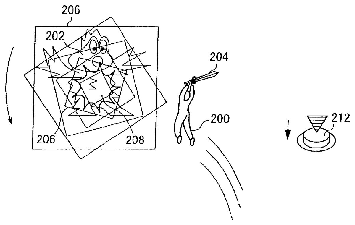
As shown inFIG. 10, when the user inputs manipulation commands for attacking one of the monsters202with a weapon204, the main character200starts running toward the selected monster202. After arriving at a position for attacking, as shown inFIG. 11, the main character200jumps up for attacking the monster202. At this time, an outer moving square (navigation mark)206and an inner stationary square (targeting point)208are displayed over the monster202. The outer square206rotates and gradually gets smaller until it becomes substantially as large as the inner square208and overlaps the inner square208. When the outer square (navigation mark)206becomes substantially as large as the inner square208and overlaps the inner square208, light is emitted from the navigation mark206.
As shown inFIG. 12, the user can simply perform a single attack by pushing the ∘ button (decision button)112dof the manual controller16. However, if the user pushes the decision button112dsimultaneously with the light-emission from the navigation mark206, it is possible to perform another attack. That is, if the user successfully pushes the decision button112dat the best timing, right when the outer moving square206overlaps the inner stationary square208, the user gets an additional attack (second attack).
If the second attack is also performed at the best timing, the user may get a third attack. In this way, the user can successively attack the monster202multiple times by manipulating the controller16at the best timing. It is possible to set the maximum number of attacks based on the level of the character200or the type of the weapon204.
If the user misses to push the decision button112dat the best timing, that is, if the user fails to push the decision button112dright when the outer moving square206overlaps the inner stationary square208, the user can not perform the additional attack any more.
When the main character200attacks the monster202, the monster202does not always sit there and take successive (multiple) attacks like an idiot. The monster202may counterattack the main character200. For example, as shown inFIG. 13, the monster202uses a counterattack barrier210when the main character200tries to attack the monster202. In this case, the user may push the x button112cof the manual controller16for defending (dodging) the counterattack. If the user fails to defend the counterattack, as shown inFIG. 14, the main character will be flicked away by the counterattack barrier210.
As shown inFIGS. 11 and 12, a button icon212indicating the timing for pressing the decision button112dmay be displayed on the right side of the display monitor18. The button icon212moves up and down synchronously with the manipulation of the decision button112d.
According to a second battle system utilizing the characteristic function of the entertainment system10, the navigation mark moves to circulate along a predetermined graphic object. The next event to be developed is determined based on the time difference between a point of time when the navigation mark reached an arbitrary point on the circulating line and a point of time when the user inputted manipulation data via the manual controller16.
The second battle system will be described specifically with reference toFIGS. 15 and 16schematically showing another battle scene of the role playing game.
As shown inFIG. 15, a transformed main character200and monsters202are displayed on the display monitor18. Further, a light-emitting point (navigation mark)222is displayed right above a circular timing meter220at the 12 o'clock position. When the user pushes the decision button112d, the navigation mark222starts to move clockwise along the circular timing meter220for one cycle until it moves back to the initial position at 12 o'clock.
If the user pushes the decision button112dagain at the best timing, right when the navigation mark222reaches the 12 o'clock position, the navigation mark222accelerates its speed and moves along the circular timing meter220again for another cycle. At this time, the number of attacks is incremented by 1. That is, if the user successfully pushes the decision button112dat the best timing, right when the navigation mark222reaches the 12 o'clock position, the navigation mark222does not stop at the 12 o'clock position and continues its movement for another cycle. Unless the user misses the timing for pushing the decision button112din every cycle, the navigation mark222continues to move for a predetermined number of cycles (for example, for five cycles). The number of attacks can be indicated by the number of arc-shaped bars224positioned around the timing meter220.
If the user misses the timing, the navigation mark222stops its movement and the number of attacks will not be incremented any more.
When the number of attacks is determined by the timing meter220, as shown inFIG. 16, the main character200successively attacks the monster202multiple times corresponding to the determined number of attacks. InFIG. 16, since three bars224are indicated, the user can successively attack the monster202three times.
Next, an example of software (event determining means300) for carrying out the characteristic function of the entertainment system10will be described with reference toFIGS. 17 through 27. For the purpose of brevity, the software (event determining means300) will be described basically in connection with a battle between a single main character200and a single monster202. However, it is to be understood that the software (event determining means300) can also be applied to a battle between a plurality of main characters200and a plurality of monsters202. For example, a main character may attack a plurality of monsters at the same time in one attack turn.
The event determining means300can be supplied from a randomly accessible recording medium such as a CD-ROM, a memory card14or the like to the entertainment apparatus12. Alternatively, the event determining means300can be downloaded via a network such as the Internet or downloaded via a satellite communication or the like to the entertainment apparatus12. In the following explanation, the event determining means300is supplied from an optical disk (e.g., CD-ROM)20.
Specifically, the optical disk20is played back by the optical controller88to read the event determining means300and the read event determining means300is stored in a main memory in the control system82of the entertainment apparatus12by a predetermined process. Thereafter, the event determining means300is executed by the CPU80of the control system82of the entertainment apparatus12.
As shown inFIG. 17, the event determining means300comprises information reading means302, battle scene displaying means304, attack turn determining means306, attack mode determining means308, first navigation mark displaying means310, counterattack mode determining means312, and counterattack processing means314. The information reading means302reads information about the main character200and the monster202from the optical disk20. The battle scene displaying means304displays images of a background, the main character200, and the monster202as a battle scene on the display monitor18. The attack turn determining means306determines whether the present attack turn is for the main character200or for the monster202. The attack mode determining means308determines whether transformation points for changing the attack mode of the main character200is the maximum or not. Further, the attack mode determining means308determines whether there is an input of a manipulation command for changing the attack mode of the main character200or not. The first navigation mark displaying means310displays the navigation mark (outer moving square)206on the display monitor18such that navigation mark206rotates and gradually gets smaller. The counterattack mode determining means312determines whether the battle will goes into a counterattack mode for the monster202to counterattack the main character200or not. The counterattack processing means314moves the monster202to counterattack the main character200on the display monitor18. Further, the counterattack processing means314subtracts damage points by the monster's counterattack from hit points of the main character200.
The event determining means300further comprises monster's attack processing means316, first attack processing means318, second attack processing means320, and end determining means322. The monster's attack processing means316moves the monster202to attack the main character200on the display monitor18. Further, the monster's attack processing means316subtracts damage points by the monster's attack from hit points of the main character200. The first attack processing means318allows the user to input manipulation data when the navigation mark206is rotating and getting smaller. Further, the first attack processing means318processes multiple attacks or a single attack of the main character200based on the manipulation data inputted by the user. Then, the first attack processing means318subtracts damage points by the main character's attack from hit points of the monster202. The second attack processing means320allows the user to input manipulation data when the navigation mark (light emitting point)222is moving clockwise (or anti-clockwise) along the timing meter220. Further, the second attack processing means320processes successive attacks or a single attack of the main character200based on the manipulation data inputted by the user. Then, the second attack processing means320subtracts damage points by the main character's attack from hit points of the monster202. The end determining means322determines the end/continuation of the battle.
As shown inFIG. 18, the counterattack processing means314comprises first counterattack displaying means330, time counting means332, key entry determining means334, counterattack defense determining means336, second counterattack displaying means338and main character's hit point subtracting means340. The first counterattack displaying means330displays a battle scene of the counterattack mode for the monster202to counterattack the main character200on the display monitor18. The time counting means332counts time until the x button112cis pressed by the user. The key entry determining means334determines whether the x button112chas been pressed by the user or not. The counterattack defense determining means336determines whether the monster's counterattack can be defended or not based on the counted time. The second counterattack displaying means338moves the main character200to be flicked away on the display monitor18. The main character's hit point subtracting means340subtracts damage points by the monster's counterattack from hit points of the main character200.
As shown inFIG. 19, the first attack processing means318comprises light emitting point displaying means350, time counting means352, key entry determining means354, attack displaying means356, button icon displaying means358, successive attack determining means360, monster's hit point subtracting means362, and transformation point accumulating means364. The light emitting point displaying means350processes light emission of the navigation mark206on the display monitor18when the navigation mark (outer moving square)206gets smaller to substantially overlaps the smaller inner stationary square (targeting point)208, i.e., when the navigation mark206stops on the targeting point208. The time counting means352starts counting time when light is emitted from the navigation mark206. The time counting means352counts time until the ∘ button (decision button)112dis pressed by the user. The counted time will be hereinafter referred to as the “input time”. The key entry determining means354determines whether the decision button112dhas been pressed by the user or not. The attack displaying means356moves the main character200to attack the monster202with the weapon202on the display monitor18. The button icon displaying means358displays a button icon212on the display monitor18such that the button icon212is pressed synchronously with the manipulation of the decision button112dby the user. The successive attack determining means360determines whether the main character200can successively attack the monster202multiple times or not based on the counted time or the maximum number of attacks M. The monster's hit point subtracting means362subtracts damage points by the main character's attack from hit points of the monster202. The transformation point accumulating means364accumulates transformation points for changing the attack mode of the main characters200.
As shown inFIG. 20, the second attack processing means320comprises transformation displaying means370, bar displaying means372, movement speed reading means376, required time calculating means378, and key entry determining means380. The transformation displaying means370displays a condition in which the main character is being transformed into a more powerful character on the display monitor18. The bar displaying means372displays arc-shaped bars224around the timing meter220successively on the display monitor18. The movement speed reading means376reads information about the movement speed of the navigation mark222from a movement speed information table374recorded in the optical disk20. The required time calculating means378calculates the required time for the navigation mark222to move around the timing meter220for one cycle. The key entry determining means380determines whether the decision button112dhas been pressed by the user or not.
The second attack processing means320further comprises time counting means382, second navigation mark displaying means384, time difference calculating means386, successive attack determining means388, attack displaying means390, monster's hit point subtracting means392, and attack end determining means394. The time counting means382starts to count time when the navigation mark222starts to move around the timing meter220. The time counting means382counts time until the decision button112dis pressed by the user. The second navigation mark displaying means384moves the navigation mark222around the timing meter220for one cycle. The time difference calculating means386calculates the time difference between the required time and the input time (counted time). The successive attack determining means388determines whether the main character200can successively attack the monster202multiple times based on the time difference. The attack displaying means390moves the main character200to attack the monster with the weapon204on the display monitor18. The monster's hit point subtracting means392subtracts damage points by the monster's attack from hit points of the main character200. The attack end determining means394determines whether the determined number of attacks have been already performed or not.
Next, the processing sequence of the event determining means300will be described with reference to flow charts ofFIGS. 21 through 27.
Firstly, as shown in Step S1ofFIG. 21, the information reading means302reads information about the monster(s)202from the optical disk20. Then, in Step S2, the information reading means302reads information about successive attacks (the maximum number of attacks M) of the main character200from the optical disk20.
Next, in Step S3, the battle scene displaying means304displays images of a background, the main character200, and the monster(s)202as a battle scene on the display monitor18. Then, the control goes to Step S4. In Step S4, the attack turn determining means306determines the attack turn. The attack turn may be determined based on a random number. Alternatively, the attack turn may be determined by a predetermined order (e.g., first turn: main character→second turn: monster→third turn: main character).
If the attack turn determining means306determines that the present attack turn is for the main character200in Step S5, the control goes to Step S6. In Step S6, the attack mode determining means308determines the present attack mode of the main character200. For example, there are two attack modes for the main character's attack, i.e., a normal attack mode and a transformation attack mode. The normal attack mode is performed when the main character200is in the normal condition. The transformation attack mode is performed when the main character200is in the transformed condition. When the main character200has gained transformation points to the maximum, the user can selectively transform the main character200into a more powerful character by inputting a manipulation command for changing the attack mode from the normal attack mode to the transformation attack mode. That is, if the transformation points is the maximum and there is an input of the manipulation command for changing the attack mode, the attack mode determining means308determines that the present attack mode of the main character is the transformation attack mode.
If it is determined that the present attack mode is not the transformation attack mode, i.e., if it is determined that the present attack mode is the normal attack mode, the control goes to Step S7for determining the action of the main character200in the normal attack mode based on a manipulation command inputted by the user. If it is determined that there is a manipulation command for attacking the monster202with the weapon204is inputted by the user, the control goes to Step S8for selecting one monster202. Then, after the monster202is selected in Step S8, the control goes to Step S9.
In Step S9, an index register i used for updating information of successive attacks is initialized by storing an initial value 0 in the index register i. Thereafter, in Step S10, as shown inFIG. 10, the battle scene displaying means304moves the main character200to start running toward the selected monster202on the display monitor18.
Next, in Step S11, as shown inFIG. 11, the first navigation mark displaying means310displays the navigation mark206on the display monitor18such that the navigation mark206rotates and gradually gets smaller. Then, the control goes to Step S12of FIG.22.
In Step S12, the counterattack mode determining means312determines whether the selected monster202is the type of a monster which performs a counterattack or not based on the information about the monster202read by the information reading means302in Step S1.
If it is determined that the monster202is not the type of a monster which performs a counterattack, the control goes to Step S13for performing the process of the first attack processing means318.
The process of the first attack processing means318will be described with reference to the flow chart of FIG.23.
In Step S101, when the rotating navigation mark206gets smaller to substantially overlap the targeting point208on the display monitor18by the process of the first navigation mark displaying means310, the light emitting point displaying means350of the first attack processing means328processes light emission of the navigation mark206.
In Step S102, the time counting means352of the first attack processing means318starts to count time when light is emitted from the navigation mark206. The time counting means352counts time until the decision button112dis pressed by the user. In Step S103, the key entry determining means354of the first attack processing means318determines whether the decision button112dhas been pressed by the user or not. If it is determined that the decision button112dhas not been pressed by the user in Step S102, the control goes to Step S104. In Step S104, it is determined whether a predetermined time has passed or not.
If it is determined that the predetermined time has passed in Step S104, that is, if it is determined that the decision button112dhas not been pressed for the predetermined time, the process of the first attack process means318is brought to an end. If it is determined that the predetermined time has not passed in Step S104, the control goes back to Step S103. If it is determined that the decision button112dhas been pressed in Step S103, that is, if it is determined that the decision button112dhas been pressed within the predetermined time, the control goes to Step S105.
In Step S105, as shown inFIG. 12, the attack displaying means356of the first attack processing means318moves the main character200to attack the monster202with the weapon204on the display monitor18. Then, in Step S106, the button icon displaying means358of the first attack processing means318displays the button icon212on the display monitor18such that the button icon212is pressed synchronously with the manipulation of the decision button112d. Then, the control goes to Step S107.
In Step S107, the successive attack determining means360of the first attack processing means318determines whether the main character200can successively (additionally) attack the monster202or not based on the counted time (input time). Specifically, it is determined that the input time is within a predetermined range or not. If it is determined that the input time is within a predetermined range, that is, if it is determined that the main character200can successively (additionally) attack the monster202, the control goes to Step S108. In Step S108, the monster's hit point subtracting means362of the first attack processing means318subtracts damage points by the main character's attack from hit points of the monster202. Thereafter, in Step S109, the transformation point accumulating means364of the first attack processing means318accumulates transformation points for changing the attack mode of the main character200.
Then, after updating the value of the index register i to be incremented by 1 in Step S110, the control goes to Step S111. In Step S111, the successive attack determining means360of the first attack processing means318determines whether the main character200can successively (additionally) attack the monster202or not based on the maximum number of attacks M. Specifically, if the value of the index register i is less than the maximum number of attacks M, the main character200can successively attack the monster202. For example, the maximum number of attacks M depends on the level of the main character200.
If it is determined that the main character200can successively attack the monster202, the control goes back to Step S10for performing the process of the next attack. If it is determined that the main character200can not successively attack the monster202, the process of the attack processing means318is brought to an end.
The main routine of the event determining means300will be described again from Step S12of FIG.22. In Step S12, if it is determined that the monster202is not the type of a monster which performs a counterattack, the control goes to Step S14. In Step S14, the counterattack mode determining means312determines whether the main character200is in the middle of successive attacks based on the value of the index register i. That is, if the value of the index register i is 1 or greater than 1, it is determined that the main character200is in the middle of successive attacks.
If it is determined that the main character200is not in the middle of successive attacks, i.e., the present attack of the main character200is a first attack, the control goes to Step S13for performing the above mentioned process of the first attack processing means318. If it is determined that the main character200is in the middle of successive attacks, the control goes to Step S15for generating a random number which is used to determine whether the battle will go into a counterattack mode for the monster202to attack the main character200or not.
Next, in Step S16, the counterattack mode determining means312determines whether the battle will go into the counterattack mode or not. Specifically, it is determined that the random number generated in Step S15is included in a group of numbers indicating the probability of counterattack or not. The groups of numbers indicating the probability of counterattack will be simply referred to as the probability numbers. The probability numbers are provided from the information about the selected monster202read in Step S1.
If it is determined that the random number is included in the probability numbers, the control goes to Step S17for performing the process of the counterattack processing means314.
The process of the counterattack processing means314will be described specifically with reference to the flow chart of FIG.24.
In Step S201ofFIG. 24, as shown inFIG. 13, the first counterattack displaying means330of the counterattack processing means314displays a battle scene of the counterattack mode for the monster202to counterattack the main character200on the display monitor18. Then, the control goes to Step S202.
In Step S202, the time counting means332of the counterattack processing means314counts time when the counterattack mode of the monster202is displayed on the display monitor18. The time counting means332counts time until the x button112cis pressed by the user. Thereafter, in Step S203, the key entry determining means334of the counterattack processing means314determines whether the x button112chas been pressed by the user or not.
If it is determined that the x button112chas not pressed by the user in Step S203, the control goes to Step S204. In Step S204, it is determined whether a predetermined time has been passed or not.
If it is determined that the predetermined time has passed in Step S204, that is, if it is determined that the x button112chas not been pressed for the predetermined time, the control goes to Step S205. In Step S205, the second counterattack displaying means338of the counterattack processing means314moves the main character200to be flicked away by the counter barrier210on the display monitor18as shown inFIG. 14, for example. Thereafter, in Step S206, the main character's hit point subtracting means340of the counterattack processing means314subtracts damage points by the monster's counterattack from hit points of the main character200. Then, the process of the counterattack processing means314is brought to an end.
If it is determined that the predetermined time has not passed in Step S204, the control goes back to Step S203. If it is determined that the x button112chas been pressed in Step S203, that is, if it is determined that the x button112chas been pressed within the predetermined time, the control goes to Step S207. In Step S207, the counter attack defense determining means336of the counter attack processing means314determines whether the monster's counterattack can be defended based on the counted time (input time). Specifically, it is determined whether the input time is within a predetermined range or not. If it is determined that the input time is not within the predetermined range, that is, if it is determined that the monster's counterattack can not be defended, the control goes to Steps S205and S206for performing the process of the second counterattack displaying means338and the process of the main character's hit point subtracting means340. That is, the main character200is flicked away by the counter barrier210and damage points by the monster's counterattack is subtracted from hit points of the main character200. Then, the process of the counterattack processing means314is brought to an end.
If it is determined that the input time is within the predetermined range, that is, if it is determined that the monster's counterattack can be defended, the control goes to Step S111ofFIG. 23for performing the process of the first attack processing means318. Specifically, as described above, the successive attack determining means360of the first attack processing means318determines whether the main character200can successively (additionally) attack the monster202or not based on the maximum number of attacks M.
The main routine of the event determining means300inFIG. 21will be described again.
In Step S7, if it is determined that the manipulation command inputted by the user is not a command for attacking the monster202with the weapon204, that is, if it is determined that the manipulation command inputted by the user is a command for casting a magic spell or a command for using an item, for example, the control goes to Step S18for performing another process depending on the type of the command.
In Step S6, if it is determined that the present attack mode is the transformation attack mode, the control goes to Step S19for performing the process of the second attack processing means320.
The process of the second attack processing means320will be described with reference to the flow charts ofFIGS. 25 and 26.
In Step S301ofFIG. 25, the transformation displaying means370of the second attack processing means320displays a condition in which the main character200is being transformed into a more powerful character. The transformed main character is shown in FIG.15. Then, the control goes to Step S302.
In Step S302, the action of the main character200in the transformation attack mode is determined based on a manipulation command inputted by the user. If it is determined that the manipulation command is a command for attacking the monster202with the weapon204, the control goes to Step S303for selecting the monster202to be targeted for attack. Then, after the monster202is selected in Step S303, the control goes to Step S304.
In Step S304, a value 1 is stored in the index register i for updating the number of attacks. Then, the control goes to Step S305.
In Step S305, the bar displaying means372of the second attack processing means320displays the i-th arc-shaped bar224around the timing meter220.
Next, in Step S306, the movement speed reading means376of the second attack processing means320reads information about the movement speed of the navigation mark222from the i-th record of a movement speed information table shown in FIG.27. Then in Step S307, the required time calculating means378of the second attack processing means320calculates the required time for the navigation mark222to move around the timing meter220for one cycle based on the movement speed read in Step S306.
Next, in Step308, the key entry determining means380of the second attack processing means320determines whether the decision button112dhas been pressed by the user or not. When it is determined that the decision button112dhas been pressed, the control goes to Step S309.
In Step S309, the second navigation mark displaying means384of the second attack processing means320moves the navigation mark222around the timing meter220for one cycle at the movement speed read in Step S306.
Then, in Step S310, the time counting means382of the second attack processing means320counts time until the decision button112dis pressed by the user.
Thereafter, in Step S311ofFIG. 26, the key entry determining means380of the second attack processing means320determines whether the decision button112dhas been pressed by the user or not. If it is determined that the decision button112dhas not been pressed, the control goes to Step S312. In Step312, it is determined whether a predetermined time has passed or not.
If it is determined that the predetermined time has passed in Step S312, that is, if it is determined that the decision button112dhas not been pressed for the predetermined time, the control goes to Step S317. The processing sequence of Step S317and the subsequent steps will be described later on.
If it is determined that the predetermined time has not passed in Step S312, the control goes back to Step S311. If it is determined that the decision button112dhas been pressed in Step S311, that is, if it is determined that the decision button has been pressed within the predetermined time, the control goes to Step S313.
In Step S313, the time difference calculating means386calculates the difference between the required time and the counted time (input time).
Then, in Step S314, the successive attack determining means388of the second attack processing means320determines whether the main character200can successively (additionally) attack the monster202or not based on the time difference. Specifically, it is determined whether the input time is within a predetermined range or not.
If it is determined that the input time is not in the predetermined range, the main character can not additionally attack the monster202. In this case, the control goes to Step S317.
If it is determined that the input time is within the predetermined range, the main character200can additionally attack the monster202. In this case, the control goes to Step S315for updating the value of the index register i to be incremented by 1. Then, the control goes to Step S316. In Step S316, it is determined whether the value of the index register i is a predetermined maximum number of attacks or greater than the predetermined maximum number of attacks (for example, i≧5) or not.
If it is determined that the value of the index register i is less than the predetermined maximum number of attacks, the control goes back to Step S305. The processing sequence of Step S305and the subsequent steps has already been described above.
If it is determined that the value of the index register i is the predetermined maximum number of attacks or greater than the predetermined maximum number of attacks, the control goes to Step S317.
In Step S317, an index register k used for counting the number of actual attacks is initialized by storing an initial value 0 in the index register k.
Next, in Step S318, the attack displaying means390of the second attack processing means320moves the main character200to fly over the monster202to attack the monster202with the weapon202on the display monitor18as shown inFIG. 16, for example. Then, in Step S319, the monster's hit point subtracting means392of the second attack processing means320subtracts damage points by the main character's attack from hit points of the monster202.
Then, after updating the value of the index register k to be incremented by 1 in Step S320, the control goes to Step S321. In Step321, the attack end determining means394of the second attack processing means320determines whether the determined number (i) of attacks have already been performed or not. Specifically, it is determined that the value of the index register k is same as or greater than the value of the index register i or not. If the vale of the index register k is same as or greater than the value of the index register i, it is determined that the determined number (i) of attacks have already been performed.
If it is determined that the determined number (i) of attacks have not been performed yet, the control goes back to Step318and the subsequent steps for performing the process of the next attack against the monster202. If it is determined that the determined number (i) of attacks have already been performed, the process of the second attack processing means320is brought to an end.
In Step S302ofFIG. 25, if it is determined that the manipulation command is not a command for attacking the monster202with the weapon204, that is, if it is determined that the manipulation command is a command for casting a spell or a command for using an item, the control goes to Step S322for performing another process based on the manipulation command.
The main routine of the event determining means300inFIG. 21will be described again from Step S5.
In Step S5, if it is determined that the present attack turn is for the monster202, the control goes to Step S20. In Step S20, the monster's attack processing means316of the event determining means300moves the monster202to attack the main character200on the display monitor18. Then, in Step S21, damage points by the monster's attack is subtracted from hit points of the main character200.
When the process of the first attack processing means318in Step S13or the process of the counterattack processing means314in Step S17ofFIG. 22is finished, or when any of the process in Step S18, the process of the second attack processing means320in Step S19, and the process in Step S21is finished, the control goes to Step S22of FIG.22.
In Step S22, the end determining means322of the event determining means300determines whether the value of the main character's hit points200is “0” or not.
If it is determined that the value of the main character's hit points is “0”, the control goes to Step S23for performing the process of “Game Over”. Then, the process of the event determining means300is brought to an end.
If it is determined that the value of the main character's hit points is not “0”, the control goes to Step S24for determining whether the value of the monster's hit points is “0” or not for each of the monsters202. If it is determined that the value of the monster's hit points is not 0 for any of the monsters202, the control goes back to Step S4and the subsequent steps for performing the next attack turn for the main character200or the monsters202. If it is determined that the value of monster's hit points is “0” for all of the monsters202, the control goes to Step S25. In Step S25, the process of gaining items, gold and experiences by the main character200is performed. Then, process of the event performing means300is brought to an end.
As described above, according the embodiment of the present invention, the entertainment system10comprises the event determining means300which moves the navigation mark202or222as time advances, and which determines the next event to be developed based on the time difference between a point of time when the navigation mark reached a predetermined position and a point of time when the user inputted manipulation data via the manual controller16.
For example, in a conventional battle scene of a role playing game, when a user tries to attack a monster202with a weapon204, after a command for attacking the monster202with the weapon204is selected by the user, an animation of the main character200for preparing an attack against the monster202with the weapon204is displayed on a display monitor18. Then, after manipulation data is inputted by the user, an animation of actually attacking the monster202with the weapon204is displayed based on the manipulation data.
However, it is not possible to create a sufficiently realistic battle scene merely by the above change of the screen image.
Therefore, according to the embodiment of the present invention, the next event is determined based on the time difference between a point of time when the navigation mark206or222reached a predetermined position and a point of time when a user inputted manipulation data via the manual controller16.
Accordingly, it is possible to determine the type of the main character's attack based on the time difference. Specifically, if the time difference is very small, an attack of a higher level (successive attacks) is displayed. If the time difference is large, an attack of a lower level (single attack) or a miss attack is displayed.
Further, it is possible to display additional attacks based on the number of successive comparison results obtained when the time difference is within a predetermined range.
Basically, a battle scene of a role playing game tends to be monotonous. However, according to the embodiment of the present invention, it is possible to make the battle scene of the role playing game highly realistic. Therefore, it is possible to prevent the user from losing interest in the battle scene of the role playing game.
Specifically, according to the present embodiment, when the rotating navigation mark206is converged into the targeting point208, that is, when the navigation mark206reaches a predetermined position, light is emitted from the navigation mark. Therefore, it is made easier for the user to recognize the right timing of the navigation mark206to reach the predetermined position. In this case, in the battle scene where the navigation mark is rotating and getting smaller, the user can perform an attack of a higher level relatively easily. Accordingly, a further amusing aspect is added to the battle scene.
Further, when the main character200is in the middle of successive attacks, since the event determining means300comprises the counterattack processing means314for processing a counterattack of the monster202against the main character200, a highly realistic battle scene can be provided for the user. Accordingly, the user may feel as if the user were fighting against the monster202.
The entertainment system, the entertainment apparatus, and the recording medium, and the program shall not be limited to the particular embodiment disclosed herein. It will be apparent to a person skilled in the art that numerous modifications and variation may be made without departing from the spirit and scope of the invention.
Claims
- An entertainment system comprising: an entertainment apparatus for executing various programs;at least one manual controller for inputting a manual control request of a user to said entertainment apparatus;and a display monitor for displaying an image outputted from said entertainment apparatus, said entertainment apparatus comprising: means for performing a first process of moving a navigation mark displayed on said display monitor in a predetermined direction as time advances;means for performing a second process of calculating a time difference between a point of time when said navigation mark reached a predetermined position and a point of time when said user inputted manipulation data via said manual controller;and means for generating an event and successively repeating said first process and said second process if the time difference is within a predetermined time, wherein said event is generated for changing a parameter of a single character.
- An entertainment system according to claim 1 , wherein a next event is determined based on a number of times said first process and said second process are repeated.
- An entertainment apparatus for executing various programs, said entertainment apparatus being connectable to at least one manual controller for inputting a manual control request of a user to said entertainment apparatus, and connectable to a display monitor for displaying an image outputted from said entertainment apparatus, said entertainment apparatus comprising: means for performing a first process of moving a navigation mark displayed on said display monitor in a predetermined direction as time advances;means for performing a second process of calculating a time difference between a point of time when said navigation mark reached a predetermined position and a point of time when said user inputted manipulation data via said manual controller;and means for generating an event and successively repeating said first process and said second process if the time difference is within a predetermined time, wherein said event is generated for changing a parameter of a single character.
- An entertainment apparatus according to claim 3 , wherein a next event is determined based on a number of times said first process and said second process are repeated.
- A computer readable medium storing a program and data for use in an entertainment system comprising: an entertainment apparatus for executing various programs;at least one manual controller for inputting a manual control request of a user to said entertainment apparatus;a display monitor for displaying an image outputted from said entertainment apparatus, said recording medium comprising: means for performing a first process of moving a navigation mark displayed on said display monitor in a predetermined direction as time advances;means for performing a second process of calculating a time difference between a point of time when said navigation mark reached a predetermined position and a point of time when said user inputted manipulation data via said manual controller;and means for successively repeating said first process and said second process if the time difference is within a predetermined time, wherein after said first process and said second process are repeated, an event is repeatedly generated for changing a parameter of a single character, and said event is repeated as many times an a number of times said first process and second process are repeated.
- A computer readable medium according to claim 5 , wherein said event is determined based on the number of times said first process and said second process are repeated.
- A method of data processing in an entertainment system comprising;an entertainment apparatus for executing various programs, at least one manual controller for inputting a manual control request of a user to said entertainment apparatus;a display monitor for displaying an image outputted from said entertainment apparatus, said method comprising the steps of: performing a first process of moving a navigation mark displayed on said display monitor in a predetermined direction as time advances;performing a second process of calculating a time difference between a point of time when said navigation mark reached a predetermined position and a point of time when said user inputted manipulation data via said manual controller;and successively repeating said first process and said second process if the time difference is within a predetermined time, wherein after said first process and said second process are repeated, an event is repeatedly generated for changing a parameter of a single character, and said event is repeated as many times as a number of times said first process and second process are repeated.
- A method according to claim 7 , wherein said event is determined based on the number of times said first process and said second process are repeated.
Disclaimer: Data collected from the USPTO and may be malformed, incomplete, and/or otherwise inaccurate.