U.S. Pat. No. 6,846,237
ENTERTAINMENT SYSTEM, ENTERTAINMENT APPARATUS, RECORDING MEDIUM, AND PROGRAM
AssigneeSony
Issue DateJanuary 23, 2002
U.S. Patent No. 6,846,237: Entertainment system, entertainment apparatus, recording medium, and program

Summary:
The ‘237 patent describes an entertainment system whereby a player can manually control the actions of his animated character with the push of a button. During gameplay, situations arise which require the player to act in response. When the user reacts to a specific scene, if the timing of the action is correct, the character will react in a certain way. If the time is not correct, however, the action sequence will be different. This patent has arisen in role-playing games mostly. An example that used it was Diablo.
Abstract:
An entertainment system comprises parameter changing means for permitting a user to input manipulation data by successively pressing a decision button when a button icon is displayed on a display monitor. Based on the manipulation data, the parameter changing means changes damage of a virtual enemy (e.g., monster). The parameter changing means comprises button icon displaying means for displaying the button icon on the display monitor for a predetermined period of time, accumulating means for counting the number of times the decision button is pressed for inputting manipulation data when the button icon is displayed on the display monitor, and damage calculating means for changing damage of the monster based on the counted number of times.
Illustrative Claim:
1. An entertainment system comprising: an entertainment apparatus for executing various programs; at least one manual controller for inputting a manual control request of a user to said entertainment apparatus; a display monitor for displaying an image outputted from said entertainment apparatus; and parameter changing means for permitting the user to input manipulation data by specific manipulation of said manual controller when a symbol indicating permission to input the manipulation data by said specific manipulation is displayed on said display monitor in a scene of a game, and for changing a predetermined parameter of a program presently executed by said entertainment apparatus based on the manipulation data inputted by said specific manipulation.
Illustrative Figure
Abstract
An entertainment system comprises parameter changing means for permitting a user to input manipulation data by successively pressing a decision button when a button icon is displayed on a display monitor. Based on the manipulation data, the parameter changing means changes damage of a virtual enemy (e.g., monster). The parameter changing means comprises button icon displaying means for displaying the button icon on the display monitor for a predetermined period of time, accumulating means for counting the number of times the decision button is pressed for inputting manipulation data when the button icon is displayed on the display monitor, and damage calculating means for changing damage of the monster based on the counted number of times.
Description
DESCRIPTION OF THE PREFERRED EMBODIMENT An embodiment of the entertainment system according to the present invention which is applied to a video game apparatus, and an embodiment of the recording medium according to the present invention which is applied to a recording medium for storing a program and data executable by the video game apparatus will be described with reference toFIGS. 1 through 15. As shown inFIG. 1, an entertainment system10basically comprises an entertainment apparatus12for executing various programs, a memory card14detachably connected to the entertainment apparatus12, a manual controller16detachably connected to the entertainment apparatus12by a connector62, and a display monitor18such as a television receiver which is supplied with video and audio output signals from the entertainment apparatus12. The entertainment apparatus12reads a program recorded in a mass storage medium such as an optical disk20such as a CD-ROM or the like, and executes a game, for example, based on the program depending on commands supplied from a user, e.g., a game player, via the manual controller16. The execution of the game mainly represents controlling the progress of the game by controlling the display of images and the generation of sounds on the display monitor18based on manual input actions entered from the manual controller16via the connector62. The entertainment apparatus12has a substantially flat casing in the shape of a rectangular parallelepiped which houses a disk loading unit22disposed centrally for loading an optical disk20for supplying an application program and data for a video game or the like. The casing supports a reset switch24for resetting a program which is being presently executed, a disk control switch26for controlling the loading of the optical disk20, a power supply switch28, and two slots30,32. The entertainment apparatus12may be supplied with the application program via a communication link, rather than being supplied from the optical disk20as the recording medium. The slots30,32have ...
DESCRIPTION OF THE PREFERRED EMBODIMENT
An embodiment of the entertainment system according to the present invention which is applied to a video game apparatus, and an embodiment of the recording medium according to the present invention which is applied to a recording medium for storing a program and data executable by the video game apparatus will be described with reference toFIGS. 1 through 15.
As shown inFIG. 1, an entertainment system10basically comprises an entertainment apparatus12for executing various programs, a memory card14detachably connected to the entertainment apparatus12, a manual controller16detachably connected to the entertainment apparatus12by a connector62, and a display monitor18such as a television receiver which is supplied with video and audio output signals from the entertainment apparatus12.
The entertainment apparatus12reads a program recorded in a mass storage medium such as an optical disk20such as a CD-ROM or the like, and executes a game, for example, based on the program depending on commands supplied from a user, e.g., a game player, via the manual controller16. The execution of the game mainly represents controlling the progress of the game by controlling the display of images and the generation of sounds on the display monitor18based on manual input actions entered from the manual controller16via the connector62.
The entertainment apparatus12has a substantially flat casing in the shape of a rectangular parallelepiped which houses a disk loading unit22disposed centrally for loading an optical disk20for supplying an application program and data for a video game or the like. The casing supports a reset switch24for resetting a program which is being presently executed, a disk control switch26for controlling the loading of the optical disk20, a power supply switch28, and two slots30,32.
The entertainment apparatus12may be supplied with the application program via a communication link, rather than being supplied from the optical disk20as the recording medium.
The slots30,32have respective upper slot units30B,32B and respective lower slots units30A,32A. Two manual controllers16may be connected respectively to the lower slots units30A,32A, and memory cards14(or unillustrated portable information terminals having the function of the memory card14) for storing flags indicative of interim game data may be connected respectively to the upper slots units30B,32B. The slots30,32(the upper slot units30B,32B and the lower slots units30A,32A) are asymmetrically shaped to prevent the connectors62and the memory cards14from being inserted in the wrong direction.
As shown inFIGS. 2 and 3, the manual controller16has first and second control pads34,36, an L (Left) button38L, an R (Right) button38R, a start button40, and a selection button42. The manual controller16also has joysticks44,46for inputting analog control actions, a mode selection switch48for selecting control modes of the joysticks44,46, and an indicator50for indicating a selected control mode. The indicator50comprises a light-emitting element such as a light-emitting diode or the like.
As shown inFIG. 2, the manual controller16has a housing104comprising an upper member100and a lower member102which are mated and joined to each other by fasteners such as screws.
As shown inFIGS. 2 and 3, a pair of left and right grips106,108projects from one side of respective opposite ends of the housing104. The left and right grips106,108are shaped so as to be gripped by the palms of left and right hands of the user or game player when the manual controller16is connected to the entertainment apparatus12and information retrieval is carried out or the game is played thereby, for example.
As shown inFIG. 3, the left and right grips106,108are progressively spaced away from each other toward their distal ends. To allow the game player to grip the left and right grips106,108comfortably for a long period of time, the left and right grips106,108are tapered from their joint with the housing104toward their distal ends, and have arcuate outer peripheral surfaces and arcuate distal end surfaces.
As shown inFIGS. 2 and 3, the first control pad34is disposed on one end of the housing104and comprises a first pressable control member (up button)110a, a second pressable control member (right button)110b, a third pressable control member (down button)110c, and a fourth pressable control member (right button)110d. The first through fourth pressable control members110a,110b,110c,110dproject on an upper surface of the housing104and are arranged in a crisscross pattern.
The first control pad34includes switch elements as signal input elements associated respectively with the first through fourth pressable control members110a,110b,110c,110d. The first control pad34functions as a directional controller for controlling the direction of movement of a displayed game character, for example. When the game player selectively presses the first through fourth pressable control members110a,110b,110c,110dto turn on or off the switch elements associated respectively with the first through fourth pressable control members110a,110b,110c,110d, the displayed game character moves in the direction corresponding to the pressed one of the first through fourth pressable control members110a,110b,110c,110d.
As shown inFIGS. 2 and 3, the second control pad36is disposed on the other end of the housing104and comprises a first pressable control member (Δ button)112a, a second pressable control member (□ button)112b, a third pressable control member (× button)112c, and a fourth pressable control member (◯ button)112d. The first through fourth pressable control members112a,112b,112c,112dproject on the upper surface of the housing104and are arranged in a crisscross pattern.
The first through fourth pressable control members112a,112b,112c,112dare constructed as independent members, and associated with respective switch elements disposed in the second control pad36.
The second control pad36serves as a function setting/performing unit for setting functions for a displayed game character assigned to the pressable control members112a-112dor performing functions of a displayed game character when the switch elements associated with the pressable control members112a-112dare turned on.
The L button38L and the R button38R are disposed on a side of the housing104remote from the left and right grips106,108and positioned respectively at the opposite ends of the housing104. As shown inFIGS. 2 and 4, the L button38L has a first left pressable control member (L1button)114aand a second left pressable control member (L2button)114b, and the R button38R has a first right pressable control member (R1button)116aand second right pressable control member (R2button)116b, respectively. The L button38L and the R button38R have respective switch elements associated respectively with the pressable control members (the L1button114a, the L2button114b, the R1button116a, and the R2button116b).
The L button38L and the R button38R serve as respective function setting/performing units for setting functions for a displayed game character assigned to the pressable control members114a,114band116a,116bor performing functions of a displayed game character when the switch elements associated with the pressable control members114a,114band116a,116bare turned on.
As shown inFIGS. 2 and 3, the manual controller16also has first and second analog control pads118,120disposed respectively at confronting corners defined between the housing104and the proximal ends of the left and right grips106,108which are joined to the housing104.
The first and second analog control pads118,120have the respective joysticks44,46which can be tilted in all directions (360°) about control shafts thereof, and respective signal input elements such as variable resistors or the like which are operable by the respective joysticks44,46. Specifically, the control shaft of the left and right joysticks44,46are normally urged to return to their neutral positions by biasing members. The left and the right joysticks44,46can be freely tilted in all directions (360°) about the axes of the control shafts.
The first and second analog control pads118,120can move a displayed game character while rotating the same or while changing its speed, and can make an analog-like action such as to change the form of a displayed character, when the game player manipulates the joysticks44,46. Therefore, the first and second analog control pads118,120are used as a control unit for entering command signals for a displayed character to perform the above movement or action.
When the mode selection switch48is pressed, it can select a control mode for allowing a command signal to be inputted from the first and second analog control pads118,120or a control mode for inhibiting a command signal from being inputted from the first and second analog control pads118,120.
When the mode selection switch48is pressed, it can also select a control mode for allowing a command signal to be inputted from the first and second analog control pads118,120and selecting the function of the first through fourth pressable control members112a,112b,112c,112dof the second control pad36or the function of the pressable control members114a,114band116a,116bof the L button38L and the R button38R. Depending on the control mode selected by the mode selection switch48, the mode indicator50flickers and changes its indication light.
As shown inFIG. 4, the left and right grips106,108projecting from the housing104are gripped respectively by the palms of the hands of the game player. The housing104is not required to be supported by fingers, and the manual controller16can be held by the hands while at least six out of the ten fingers of the hands can freely be moved.
As shown inFIG. 4, when the first and second grips106,108are gripped respectively by the palms of the hands of the game player, the thumbs Lf1, Rf1of the left and right hands can extend over the joysticks44,46of the first and second analog control pads118,120, the first through fourth pressable control members110a-110dof the first control pad34, and the first through fourth pressable control members112a-112dof the second control pad36, and can selectively press the joysticks44,46, the pressable control members110a-110d, and the pressable control members112a-112d.
Since the joysticks44,46of the first and second analog control pads118,120are positioned in confronting relation to the proximal ends of the left and right grips106,108which are joined to the housing104, when the left and right grips106,108are gripped by the left and right hands, the joysticks44,46are positioned most closely to the thumbs Lf1, Rf1, respectively. Therefore, the joysticks44,46can easily be manipulated by the thumbs Lf1, Rf1.
As shown inFIG. 4, when the left and right grips106,108are gripped respectively by the palms of the hands of the game player, the index fingers Lf2, Rf2and middle fingers Lf3, Rf3of the left and right hands can extend over positions where they can selectively press the L1button114a, L2button114bof the L button38L and R1button116a, R2button116bof the R button38R.
As shown inFIG. 5, the manual controller16has a pair of vibration imparting mechanisms128L,128R for imparting vibrations to the user in order for the user to be able to play a highly realistic game.
As shown inFIG. 5, the left and right vibration imparting mechanisms128L,128R are positioned near the proximal ends of the left and right grips106,108that are held by the hands and fingers when the manual controller16is gripped by the user.
Since the both vibration imparting mechanisms128L,128R have basically the same structure except their vibration characteristics, only the right vibration imparting mechanism128R will be described for the purpose of brevity.
The vibration imparting mechanisms128R comprises a motor130R energizable by a vibration generating command supplied from the entertainment apparatus12, and an eccentric member134R mounted eccentrically on the drive shaft of the motor130R.
The eccentric member134R comprises a weight in the form of a heavy metal member having a semicircular cross-sectional shape. The weight has an off-center hole defined therein in which the drive shaft of the motor130R is fitted.
According to the vibration imparting mechanisms128L,128R as constructed above, when the motors130L,130R are energized, the drive shafts thereof rotate to cause the eccentric members134L,134R to rotate in an eccentric motion for thereby generating vibrations, which are imparted to the left grip106and the right grip108. Then, the vibrations of the left grip106and the right grip108are applied to the hands and fingers of the user.
Next, the vibration characteristics of the vibration imparting mechanisms128L,128R disposed in the left grip106and the right grip108respectively will be described hereinbelow.
The vibration imparting mechanisms128L,128R have the different vibration characteristics.
For example, the motor130L of the left vibration imparting mechanism128L is bigger than the motor130R of the right vibration mechanism128R. The rotational speed of the motor130L varies according to a vibration value included in a vibration generating command transmitted from the entertainment apparatus12. That is, vibrations having different frequencies can be generated depending on the vibration value. In the present embodiment, the vibration frequency of the motor130L varies in proportion to the vibration value.
In contrast to the motor130L of the left vibration mechanism128L, the vibration frequency of the motor130R of the right vibration mechanism128R does not vary according to the vibration value included in the vibration generating command. The motor130R of the right vibration mechanism128R is simply energized or deenergized according to the vibration value. If the vibration value (logic value) is “1”, the motor130R of the right vibration mechanism128R is energized. If the vibration value is “0”, the motor130R of the right vibration mechanism128R is deenergized. When the motor130R of the right vibration mechanism128R is energized, it rotates at a constant speed to generate vibrations at a constant frequency.
In order to energize the motors130L,130R to vibrate the manual controller16in its entirety, a bidirectional communication function needs to be provided between the manual controller16and the entertainment apparatus12. This bidirectional communication function will be described later on.
Next, circuit arrangements of the entertainment apparatus12and the manual controller16will be described below with reference toFIGS. 6 through 8.
As shown inFIG. 6, the entertainment apparatus12comprises a control system82including a central processing unit (CPU)80and peripheral devices thereof, a graphic system84including a frame buffer (not illustrated) and a graphic processing unit (GPU) for rendering image data in the frame buffer, a sound system86including a sound processing unit (SPU) for generating music sounds and sound effects, an optical disk controller88for controlling the readout of the optical disk20in which application programs and data are stored, a communication controller90for controlling the inputting of data into and outputting of data from the manual controller16and the memory card14, and a system bus92to which the control system82, the graphic system84, the sound system86, the optical disk controller88, and the communication controller90are connected.
Video and audio signals generated by and outputted from the graphic system84and the sound system86are supplied to the display monitor18to display images on the monitor screen of the display monitor18and reproduce sounds from the speakers of the display monitor18.
As shown inFIG. 7, the manual controller16comprises a communication controller150, a CPU152, a program memory154, a working RAM156, a digital input block158, an analog input block160, the left motor driver170L, the left motor130L, the right motor driver170R, and the right motor130R.
These components of the manual controller16are connected to a bus162.
The digital input block158functions as a manual input controller for the first through fourth pressable control members110a-110dof the first control pad34and the first through fourth pressable control members112a-112dof the second control pad36. The analog input block160functions as a manual input controller for the left and right joysticks44,46. The digital input block158and the analog input block160allow the user to enter various items of information into the manual controller16.
The communication controller150has a function to effect serial communications with an external device. The communication controller150is electrically connectable to the communication controller90of the entertainment apparatus12(see FIG.6), for example, for data communication with the entertainment apparatus12.
As shown inFIG. 8, the bidirectional communication function between the entertainment apparatus12and the manual controller16can be performed when the connector62capable of performing bidirectional serial communications with the manual controller16is connected to the entertainment apparatus12.
A system in the manual controller16for performing the bidirectional communication function comprises a serial I/O interface SIO for performing serial communication with the entertainment apparatus12, a parallel I/O interface PIO for entering manipulation data from a plurality of control buttons, a one-chip microcomputer comprising a CPU, a RAM, and a ROM, and motor drivers170R,170L for energizing the motors130R,130L of the vibration imparting mechanisms128R,128L. The motors130R,130L are energized for rotation by voltages and currents supplied from the corresponding motor drivers170R,170L.
A system in the entertainment apparatus12for performing the bidirectional communication function comprises a serial I/O interface SIO for performing serial communication with the manual controller16. When the connector62is connected to the serial I/O interface SIO of the entertainment apparatus12, the serial I/O interface SIO of the entertainment apparatus12is connected to the serial I/O interface SIO of the manual controller16via the connector62for performing bidirectional communications between the manual controller16and the entertainment apparatus12. Other structural details of the entertainment apparatus12are omitted from illustration in FIG.8.
Signal and control lines for bidirectional serial communications include a data transfer signal line TXD (Transmit X′ for Data) for sending data from the entertainment apparatus12to the manual controller16, a data transfer signal line RXD (Received X′ for Data) for sending data from the manual controller16to the entertainment apparatus12, a serial synchronous clock signal line SCK (Serial Clock) for extracting data from the data transfer signal lines TXD, RXD, a control line DTR (Data Terminal Ready) for establishing and cutting off communication with the manual controller16as a terminal, and a flow control line DSR (Data Set Ready) for transferring a large amount of data.
The signal and control lines for bidirectional serial communication are accommodated in a cable. As shown inFIG. 8, this cable further includes a power line172extending from a power supply in the entertainment apparatus12and connected to the motor drivers170R,170L in the manual controller16for supplying electric energy to energize the motors130R,130L.
A process of bidirectional serial communication between the manual controller16and the entertainment apparatus12will be described below. In order for the entertainment apparatus12to communicate with the manual controller16to read manipulation data from the digital input block158and the analog input block160, the entertainment apparatus12first outputs selection data to the control line DTR. As a result, the manual controller16confirms that it is selected by the control line DTR, and then waits for a signal from the signal line TXD. Then, the entertainment apparatus12outputs an identification code indicative of the manual controller16to the data transfer signal line TXD. The manual controller16receives the identification code from the signal line TXD.
When the manual controller16recognizes the identification code, the manual controller16starts communicating with the entertainment apparatus12. The entertainment apparatus12sends manipulation data via the data transfer signal line TXD to the manual controller16, which sends the manipulation data from the digital input block158and the analog input block160to the entertainment apparatus12via the data transfer signal line RXD. In this manner, the entertainment apparatus12and the manual controller16perform bidirectional serial communications. The bidirectional serial communications will be finished when the entertainment apparatus12outputs selection stop data via the control line DTR.
With the bidirectional serial communication function, the manual controller16can send mainly manipulation data from the digital input block158and the analog input block160to the entertainment apparatus12, and the entertainment apparatus12can send a vibration generating command for energizing the motors130R,130L of the vibration imparting mechanisms128R,128L via the data transfer signal line TXD to the manual controller16.
The vibration generating command for energizing the motors130R,130L has been established in advance in the optical disk20set in the entertainment apparatus12. Alternatively, the vibration generating command is generated by the entertainment apparatus12.
Next, a characteristic function of the entertainment system10according to the present embodiment will be described below with reference toFIGS. 9 through 15.
The characteristic function of the entertainment system10is to permit a user to input manipulation data by specific manipulation of the manual controller16when a symbol indicating permission to input the manipulation data by the specific manipulation is displayed on the display monitor18, and to change a predetermined parameter of a program presently executed by the entertainment apparatus12based on the manipulation data inputted by the specific manipulation.
A battle system of a role playing game utilizing the characteristic function of the entertainment system10will be described specifically.
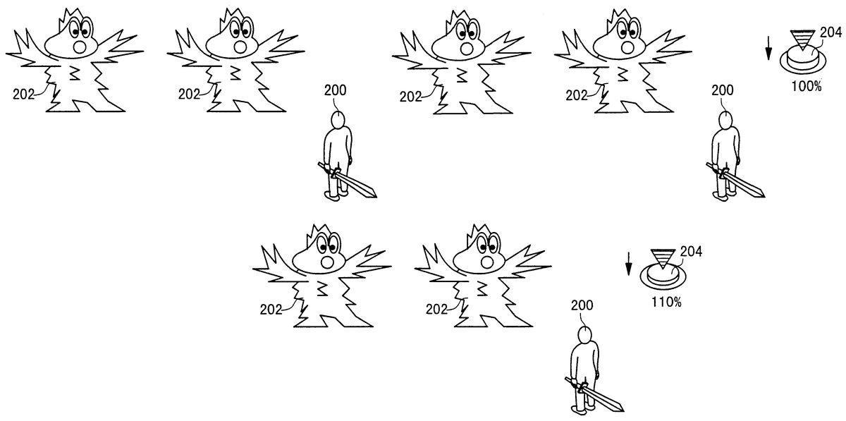
As shown inFIG. 9, when the user enters a battle, a main character200and monsters (enemies)202are displayed on the display monitor18.
At this time, the user is requested to input a manipulation command for determining an action in the battle. It is to be understood that there are several types of actions such as “attack a monster with a weapons”, “cast a magic spell”, “defend (parry) the monster's attack” and “use an item” depending on the nature of the game.
If the user inputs a manipulation command for casting a magic spell or using an item, the user is requested to input a manipulation command for selecting a magic spell or an item. If the user selects a magic spell or a magic item for performing a magic attack, the user is requested to select one monster202to be targeted for attack from the monsters202in the battle scene. The user may be requested to select a plurality of monsters202depending on the level of the magic spell or the like.
As shown inFIG. 10, when the user inputs manipulation commands for attacking one of the monsters202with a magic spell or a magic item, an icon204appears on the right side of the display monitor18. The icon204moves synchronously with the manipulation of the decision button112d(the icon204will be referred to as the “button icon”). Further, a number indicating a level of a parameter (magic power) of the selected magic spell or magic item is displayed as a power meter near the button icon204. Specifically, the number indicates a rate for changing the parameter of the magic power of the selected magic spell or magic item. The number will be referred to as the changing rate. The degree of changing the magic power is determined by the changing rate. InFIG. 10, for example, the initial value “100%” of the parameter is shown on the display monitor18. The value “100%” indicates the basic power of the selected magic spell or magic item.
The level for each of the graphic effect, sound effect, and vibration effect of the magic attack against the monster202with the selected magic spell or magic item is determined by the changing rate. The description of the graphic effect, sound effect, and vibration effect will be given later on.
While the button icon204is being displayed on the display monitor18, the user is given a chance to increase the power of the selected magic spell or magic item by pressing the decision button112dmultiple times. Specifically, in order to increase the effect of the magic attack, it is necessary for the user to press the decision button112drapidly as many times as possible. The number of button pressings by the user is counted such that the changing rate reflects the counted number. InFIG. 11, if the user presses the decision button112dfive times, for example, the changing rate is increased up to 110%. If the changing rate is increased up to 200% by pressing the decision button112dmultiple times, the damage points of the magic attack is increased to be twice as large as the basic damage points of the magic attack.
As described above, when the button icon204is displayed on the monitor18, the user can increase the changing rate of the magic power by pressing the decision button112dmultiple times so as to increase the damage points of the magic attack. At this time, the levels of the respective graphic effect, sound effect, and vibration effect are also increased based on the changing rate.
The graphic effect, sound effect and vibration effect of the magic attack against the monster202will be described briefly. There are different types of magic such as fire magic, wind magic, thunder magic, meteor magic, and poison magic. For example, the graphic effects of the fire magic, wind magic, and meteor magic can be achieved by displaying a flame, a hurricane, falling stones over the monster202, respectively. The graphic effect of the poison magic can be achieved by displaying a poisonous gas field around the monster202. According to the battle system of the present embodiment, different levels of the graphic effect can be achieved by the following manner. For example, in the case of the fire magic, different levels of the graphic effect can be achieved by changing the size or color of the flame over the monster202depending on the changing rate of the magic power of the selected magic spell or magic item. In the case of the wind magic, the size of the hurricane over the monster202may be changed. In the case of the meteor magic, the number or sizes of the falling stones may be changed. Further, in the case of the poison magic, the size of the poisonous gas field may be changed.
Further, different levels of the sound effect can be achieved by changing the tone or volume of the sound. For example, in the case of the fire magic, there are four levels of the sound effect. If the changing rate is low, a small frizzling sound is generated. If the changing rate is high, a large roaring sound is generated.
Different levels of the vibration effect can be achieved by changing the vibration level of the vibration imparting mechanisms128R,128L provided in the manual controller16depending on the changing rate. Further, the vibration level for vibrating images on the display monitor18may also be changed depending on the changing rate.
Next, an example of software (parameter changing means300) for carrying out the characteristic function of the entertainment system10will be described with reference toFIGS. 12 through 15. For the purpose of brevity, the software (parameter changing means300) will be described basically in connection with a battle between a single main character200and a single monster202. However, it is to be understood that the software (parameter changing means300) can also be applied to a battle between a plurality of main characters200and a plurality of monsters202.
The parameter changing means300can be supplied from a randomly accessible recording medium such as a CD-ROM, a memory card14or the like to the entertainment apparatus12. Alternatively, the parameter changing means300can be downloaded via a network such as the Internet or downloaded via a satellite communication or the like to the entertainment apparatus12. In the following explanation, the parameter changing means300is supplied from an optical disk (e.g., CD-ROM)20.
Specifically, the optical disk20is played back by the optical controller88to read the parameter changing means300and the read parameter changing means300is stored in a main memory in the control system82of the entertainment apparatus12by a predetermined process. Thereafter, the parameter changing means300is executed by the CPU80of the control system82of the entertainment apparatus12.
As shown inFIG. 12, the parameter changing means300comprises information reading means302, battle scene displaying means304, attack turn determining means306, accumulating means308, icon displaying means310, and data entry determining means312. The information reading means302reads information about the main character200and the monster202from the optical disk20. The battle scene displaying means displays images of a background, the main character200, and the monster202as a battle scene on the display monitor18. The attack turn determining means306determines whether the present attack turn is for the main character200or the monster202. The accumulating means308accumulates the changing rate (percentage points) for changing a magic power. The icon displaying means310displays the button icon204on the display monitor18. The data entry determining means312determines whether the decision button112has been pressed or not.
Further, the parameter changing means300comprises changing rate displaying means314, time counting means316, time determining means318, damage calculating means320, monster's hit point subtracting means322, effect changing means323, monster's attack processing means324, and end determining means326. The changing rate displaying means314displays a number indicating the changing rate on the display monitor18. The time counting means316starts counting time when the button icon204is displayed on the display monitor18. The time counting means316counts time until a predetermined time has passed. The time determining means318determines whether the predetermined time has passed or not. The damage calculating means320calculates damage points by the present magic attack based on the level of the main character200, the selected magic spell or magic item, and the changing rate. The monster's hit point subtracting means322subtracts damage points by the magic attack of the main character200from hit points of the monster202. The effect changing means323changes the levels of the respective graphic effect, sound effect, and vibration effect based on the changing rate. The monster's attack processing means324moves the monster202to attack the main character200on the display monitor18. Further, the monster's attack processing means324subtracts damage points by the monster's attack from hit points of the main character200. The end determining means326determines the end/continuation of the battle.
Next, the processing sequence of the parameter changing means300will be described with reference to flow charts ofFIGS. 13 through 15.
Firstly, as shown in Step S1ofFIG. 13, the information reading means302reads information about the main character200and the monster(s)202from the optical disk20.
Next, in Step S2, the battle scene displaying means304displays images of a background, the main character200, and the monster(s)202as a battle scene on the display monitor18. Then, the control goes to Step S3. In Step S3, the attack turn determining means306determines the attack turn. The attack turn may be determined based on a random number. Alternatively, the attack turn may be determined by a predetermined order (e.g., first turn: main character→second turn: monster→third turn: main character).
If the attack turn determining means306determines that the present attack turn is for the main character200in Step S4, the control goes to Step S5for determining the action of the main character200. If it is determined that manipulation commands for attacking a monster202with a magic spell or a magic item are inputted by the user via the manual controller18, the control goes to Step S6. In Step S6, a monster202to be targeted for the magic attack is selected from the monsters202in the battle scene.
Then, in Step S7, the accumulating means308initializes a register M used for updating information of the changing rate (percentage points) by storing an initial value100in the register M.
Next, in Step S8, as shown inFIG. 10, the icon displaying means310displays the button icon204on the right side of the display monitor18. In Step S9, the changing rate displaying means314displays the present changing rate near the button icon204. InFIG. 10, a percentage value “100%” is displayed as the changing rate on the display monitor18. Further, in Step S10, the time counting means316starts counting time. The time counting means316counts time until a predetermined time has passed.
Then, in Step S11ofFIG. 14, the data entry determining means312determines whether the decision button112dhas been pressed by the user or not. If it is determined that the decision button112dhas not been pressed by the user in Step S1, the control goes to Step S12. In Step S12, the time determining means318determines that whether the predetermined time has passed or not.
If it is determined that the predetermined time has passed in Step S12, that is, if it is determined that the decision button112dhas not been pressed for the predetermined time, the control goes to Step S17. If it is determined that the predetermined time has not passed in Step S12, the control goes back to Step S11.
If it is determined that the decision button112dhas been pressed in Step S11, that is, if it is determined that the decision button112dhas been pressed within the predetermined time, the control goes to Step S13. In Step S13, the icon displaying means310displays the button icon204on the display monitor18such that the button icon204is pressed synchronously with the manipulation of the decision button112dby the user.
Then, in Step S14, the accumulating means308accumulates the changing rate (percentage points) for changing the magic power. Specifically, the accumulating means308updates the value of register M to be incremented by 1. Thereafter, in Step S15, the icon displaying means310displays the present changing rate near the button icon204.
Next, in Step S16, the time determining means318determines that whether the predetermined time has passed or not. If it is determined that the predetermined time has not passed, the control goes back to Step S11for determining whether the decision button112has been pressed again by the user or not.
If it is determined that the predetermined has passed in Step S16, the control goes to Step S17. In Step S17, the icon displaying means318stops the display of the button icon204. Then, the control goes to Step S18.
In Step S18, the effect changing means323reads graphic data, sound data, and vibration data from the optical disk20for performing the magic attack of the selected magic spell or magic item. In this case, different levels of graphic data, sound data, and vibration data are stored in the optical disk20for achieving different levels of the graphic effect, sound effect and vibration effect. The respective levels of the graphic data, sound data, vibration data read by the effect changing means323are determined by the level of the selected magic spell or magic item, and the changing rate of the magic power.
Then, in Step S19, the effect changing means323outputs the read graphic data and sound data via the display monitor18. Further, the effect changing means323outputs the read vibration data via the vibration imparting mechanisms128L,128R of the manual controller16. In this manner, the graphic, sound and vibration for the present magic attack of the selected magic spell or magic item can be generated based on the changing rate.
Then, in Step S20, the damage calculating means320calculates damage points of the present magic attack. According to the battle system of the present embodiment, the damage calculating means320calculates the damage points of the magic attack based on a predetermined damage points determined by the level of the main character200, the selected type or level of the magic spell or magic item, and the changing rate. Then, the control goes to Step S21.
In Step S21, the monster's hit point subtracting means322subtracts the calculated damage points by the magic attack of the main character200from hit points of the monster202.
In Step S5ofFIG. 13, if it is determined that the manipulation command inputted by the user is not a command for attacking the monster202with a magic spell or a magic item, that is, if it is determined that the manipulation command inputted by the user is a command for attacking the monster202with a weapon or a command for using a non-magic item, the control goes to Step S22for performing another process depending on the type of the command.
In Step S4ofFIG. 13, if the attack turn determining means306determines that the present attack turn is for the monster202, the control goes to Step S23for performing the process of the monster's attack processing means324. In Step23, the monster's attack processing means324moves the monster202to attack the main character200on the display monitor18. Then, in Step S24, the monster's attack processing means324subtracts damage points by the monster's attack from hit points of the main character200.
When any one of the process in Step S21ofFIG. 14, the process in Step S22and the process in Step S24ofFIG. 13is finished, the control goes to Step S25of FIG.15.
In Step S25, the end determining means326determines whether the value of the main character's hit points is “0” or not.
If it is determined that the value of the main character's hit points is “0”, the control goes to Step S26for performing the process of “Game Over”. Then, the process of the parameter changing means300is brought to an end.
If it is determined that the value of the main character's hit points is not “0”, the control goes to Step S27for determining whether the value of the monster's hit points is “0” or not for each of the monsters202. If it is determined that the value of the monster's hit points is not “0” for any of the monsters202, the control goes back to Step S3and the subsequent steps for performing the next attack turn for the main character200or the monsters202. If it is determined that the value of monster's hit points is “0” for every monster202, the control goes to Step S28. In Step S28, the process of gaining items, gold and experiences by the main character200is performed. Then, process of the parameter changing means300is brought to an end.
As described above, according to the embodiment of the present invention, the entertainment system10comprises the parameter changing means300for permitting a user to input manipulation data by successively pressing the decision button112dof the manual controller16while the button icon204is being displayed on the display monitor18. Based on the manipulation data, the parameter changing means300changes a predetermined parameter of a program presently executed by the entertainment apparatus12such as a parameter for damage points of the monster202, a parameter for a graphic effect, a parameter for a sound effect, and a parameter for a vibration effect, with respect to the magic attack of a magic spell or a magic item.
For example, in a conventional battle scene of a role playing game, when a user tries to attack a monster202with a magic spell or a magic item, a predetermined animation for the selected magic spell or magic item is displayed on the display monitor18. Then, predetermined damage points by the magic spell or magic item are subtracted from hit points of the monster202. In this case, since it is not possible for the user to input data or commands via the manual controller18during the animation of the magic attack, the user can only passively view the progress of the animation. Therefore, the user can not feel actively participating in the battle. Consequently, the battle scene tends to be monotonous.
However, according to the present embodiment, the user is permitted to input specific manipulation data via the manual controller16(for example, the user can input manipulation data by pressing the decision button112dsuccessively) for changing damage points by the main character's attack against the monster202and changing the effects of the magic attack such as the graphic effect, sound effect, and vibration effect. Thus, it is possible for the user to actively participate in the battle. Accordingly, a further amusing aspect can be added to the role playing game.
That is, according to the present embodiment, it is possible to reflect manipulation data inputted by specific manipulation of the user on the effects of the magic spell or magic item in the battle scene of the role playing game. Therefore, it is possible to prevent the user from losing interest in the game.
Though the parameter changing means300has been described in connection with a battle scene of a role playing game, it is to be understood that the parameter changing means300can be applicable to a shooting game, a fighting game or the like.
The entertainment system, the entertainment apparatus, and the recording medium, and the program shall not be limited to the particular embodiment disclosed herein. It will be apparent to a person skilled in the art that numerous modifications and variation may be made without departing from the spirit and scope of the invention.
Claims
- An entertainment system comprising: an entertainment apparatus for executing various programs;at least one manual controller for inputting a manual control request of a user to said entertainment apparatus;a display monitor for displaying an image outputted from said entertainment apparatus;and parameter changing means for permitting the user to input manipulation data by specific manipulation of said manual controller when a symbol indicating permission to input the manipulation data by said specific manipulation is displayed on said display monitor in a scene of a game, and for changing a predetermined parameter of a program presently executed by said entertainment apparatus based on the manipulation data inputted by said specific manipulation.
- An entertainment system according to claim 1 , further comprising means for indicating whether said specific manipulation has been performed by the user correctly.
- An entertainment system according to claim 1 , wherein said parameter changing means displays said symbol on said display monitor when there is a request from the user to trigger a specific event in said scene, and changes said predetermined parameter while said symbol is displayed on said display monitor.
- An entertainment system according to claim 1 , wherein said symbol is displayed on said display monitor when there is a request from the user to trigger a specific event, and said predetermined parameter is used for determining an effect of said specific event.
- An entertainment apparatus for executing various programs, said entertainment apparatus being connectable to at least one manual controller for inputting a manual control request of a user to said entertainment apparatus, and connectable to a display monitor for displaying an image outputted from said entertainment apparatus, wherein said entertainment apparatus comprises parameter changing means for permitting the user to input manipulation data by specific manipulation of said manual controller when a symbol indicating permission to input the manipulation data by said specific manipulation is displayed on said display monitor in a scene of a game, and for changing a predetermined parameter of a program presently executed by said entertainment apparatus based on the manipulation data inputted by said specific manipulation.
- An entertainment apparatus according to claim 5 , wherein said entertainment apparatus further comprises means for indicating whether said specific manipulation has been performed by the user correctly.
- An entertainment apparatus according to claim 5 , wherein said parameter changing means displays said symbol on said display monitor when there is a request from the user to trigger a specific event in said scene, and changes said predetermined parameter while said symbol is displayed on said display monitor.
- An entertainment apparatus according to claim 5 , wherein said symbol is displayed on said display monitor when there is a request from the user to trigger a specific event, and said predetermined parameter is used for determining an effect of said specific event.
- A recording medium storing a program and data for use of an entertainment system, said entertainment system comprising: an entertainment apparatus for executing various programs;at least one manual controller for inputting a manual control request of a user to said entertainment apparatus;and a display monitor for displaying an image outputted from a said entertainment apparatus;wherein said program comprises means for changing a parameter comprising: means for permitting the user to input manipulation data by specific manipulation of said manual controller when a symbol indicating permission to input the manipulation data by said specific manipulation is displayed on said display monitor in a scene of a game;and means for changing a predetermined parameter of a program presently executed by said entertainment apparatus based on the manipulation data inputted by said specific manipulation.
- A recording medium according to claim 9 , wherein said program further comprises means for indicating whether said specific manipulation has been performed by the user correctly.
- A recording medium according to claim 9 , wherein said program further comprises means for displaying said symbol on said display monitor when there is a request from the user to trigger a specific event in said scene, and means for changing said predetermined parameter while said symbol is displayed on said display monitor.
- A recording medium according to claim 9 , wherein said symbol is displayed on said display monitor when there is a request from the user to trigger a specific event, and said predetermined parameter is used for determining an effect of said specific event.
- A program stored in a computer readable medium, said program readable and executable by a computer, said program being for use of an entertainment system comprising: an entertainment apparatus for executing various programs;at least one manual controller for inputting a manual control request of a user to said entertainment apparatus;and a display monitor for displaying an image outputted from said entertainment apparatus;wherein said program comprises: means for permitting the user to input manipulation data by specific manipulation of said manual controller when a symbol indicating permission to input the manipulation data by said specific manipulation is displayed on said display monitor in a scene of a game;and means for changing a predetermined parameter of a program presently executed by said entertainment apparatus based on the manipulation data inputted by said specific manipulation.
- A program stored in a computer readable medium according to claim 13 , further comprising means for indicating whether said specific manipulation has been performed by the user correctly.
- A program stored in a computer readable medium according to claim 13 , wherein said program further comprises means for displaying said symbol on said display monitor when there is a request from the user to trigger a specific event in said scene, and means for changing said predetermined parameter while said symbol is displayed on said display monitor.
- A program stored in a computer readable medium according to claim 13 , wherein said symbol is displayed on said display monitor when there is a request from the user to trigger a specific event, and said predetermined parameter is used for determining an effect of said specific event.
- An image processor for use of an entertainment apparatus, comprising: means for displaying a symbol for a predetermined period of time on a display monitor in a scene of a game;means for determining an effect of the user's action based on manipulation data inputted by a user when said symbol is displayed on said display monitor;means for generating an image according to said effect of the user's action;and means for outputting an image to said display monitor.
- An image processing method comprising the steps of: displaying a symbol for a predetermined period of time on a display monitor in a scene of a game;determining an effect of the user's action based on manipulation data inputted by a user when said symbol is displayed on said display monitor;generating an image according to said effect of the user's action;and outputting an image to said display monitor.
Disclaimer: Data collected from the USPTO and may be malformed, incomplete, and/or otherwise inaccurate.