U.S. Pat. No. 6,789,771
VIDEO GAME CONTROLLER HOLSTER
Issue DateMarch 26, 2002
Illustrative Figure
Abstract
No abstract is available for this record.
Description
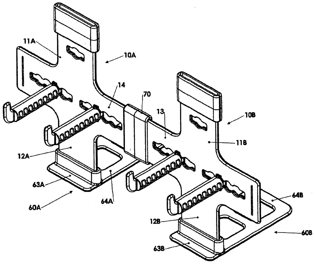
While the invention will be described in connection with a preferred embodiment, it will be understood that it is not intended to limit the invention to that embodiment. On the contrary, it is intended to cover all alternatives, modifications and equivalents as may be included within the spirit and scope of the invention as defined by the appended claims. DETAILED DESCRIPTION Turning first to FIGS. 1 and 2 , a holster for a video game controller is illustrated. A cross 10 has upward 11 , downward 12 , left 13 and right 14 projections extending outwardly from an intersection 15 of vertical and horizontal axes 16 and 17 , respectively. Each of the projections 11 , 12 , 13 and 14 , ends in a neck 18 , 19 , 21 and 22 , respectively. All of the necks 18 , 19 , 21 and 22 are isometrically dimensioned or identical. They are also isometrically located in relation to their axes 16 and 17 . Thus, the vertical necks 18 and 19 are vertically aligned and the horizontal necks 21 and 22 are horizontally aligned. In the preferred embodiment as shown, the vertical axis 16 bisects the cross 10 and the cross 10 is symmetrical about the vertical axis 16 . Similarly, the horizontal axis 17 bisects the cross 10 . However, while this is preferred to provide balance in an assembly of multiple crosses 10 as is hereinafter discussed, this is not necessary provided the vertical necks 18 and 19 are aligned with each other and identically dimensioned and the horizontal necks 21 and 22 are aligned with each other and identically dimensioned. The cross 10 has a pair of spaced apart rods 31 and 32 extending forwardly from the left and right projections 13 and 14 , respectively. ...
While the invention will be described in connection with a preferred embodiment, it will be understood that it is not intended to limit the invention to that embodiment. On the contrary, it is intended to cover all alternatives, modifications and equivalents as may be included within the spirit and scope of the invention as defined by the appended claims.
DETAILED DESCRIPTION
Turning first to FIGS. 1 and 2 , a holster for a video game controller is illustrated. A cross 10 has upward 11 , downward 12 , left 13 and right 14 projections extending outwardly from an intersection 15 of vertical and horizontal axes 16 and 17 , respectively. Each of the projections 11 , 12 , 13 and 14 , ends in a neck 18 , 19 , 21 and 22 , respectively. All of the necks 18 , 19 , 21 and 22 are isometrically dimensioned or identical. They are also isometrically located in relation to their axes 16 and 17 . Thus, the vertical necks 18 and 19 are vertically aligned and the horizontal necks 21 and 22 are horizontally aligned. In the preferred embodiment as shown, the vertical axis 16 bisects the cross 10 and the cross 10 is symmetrical about the vertical axis 16 . Similarly, the horizontal axis 17 bisects the cross 10 . However, while this is preferred to provide balance in an assembly of multiple crosses 10 as is hereinafter discussed, this is not necessary provided the vertical necks 18 and 19 are aligned with each other and identically dimensioned and the horizontal necks 21 and 22 are aligned with each other and identically dimensioned.
The cross 10 has a pair of spaced apart rods 31 and 32 extending forwardly from the left and right projections 13 and 14 , respectively. The controller (not shown) will be supported on the holster by resting the controller on the rods 31 and 32 . The typical controller has an elongated body with transverse wraps and the wraps will be seated on the rods 31 and 32 with body extending downwardly between the rods 31 and 32 . Each of the rods 31 and 32 has a detent 33 and 34 , respectively, extending upwardly at its forward end to prevent the controller from sliding in a forward direction off the rods 31 and 32 . In the preferred embodiment shown, each of the horizontal projections 13 and 14 has an elongated slot 35 and 36 , respectively, extending through it. As shown, the slots 35 and 36 are aligned on the horizontal axis 17 of the horizontal projections 13 and 14 . However, the axis of the slots 35 and 36 need not be coincident with the horizontal axis 17 . As shown, the rearward ends 37 and 38 of the rods 13 and 14 are engagable in the slots 35 and 36 so that the distance 39 between the rods can be varied. This permits the holster to be adapted to accommodate any of a variety of differently structured controllers (not shown). Furthermore, in the preferred embodiment shown, each of the slots 35 and 36 has a plurality of widened segments or portions 41 and 42 , respectively, dispersed at intervals along the length of the slots 35 and 36 . Furthermore, the rearward ends 37 and 38 of the rods 31 and 32 are approximately elliptical in cross-section so that they can be inserted into the widened segments 41 and 42 with the detents 33 and 34 aligned horizontally and rotatively engaged in or disengaged from the widened segments 41 and 42 as the rods 31 and 32 are rotated to align the detents 33 and 34 in an upward orientation. In the preferred embodiment shown, the rods 31 and 32 have forward prongs 43 and 44 and rearward prongs 45 and 46 which engage with the front and back surfaces of the left and right projections 13 and 14 of the cross 10 when the rods 31 and 32 are engaged in the slots 35 and 36 with their detents 33 and 34 in the upward orientation. Finally, as best seen in FIG. 2 , the prongs 45 and 46 and left and right projections 13 and 14 are provided with complementary dimples and nodules 47 and 48 so that the rods 31 and 32 can be locked in engagement in the slots 35 and 36 when the detents 33 and 34 are aligned in the upward orientation.
Continuing to look at FIGS. 1 and 2 , the cross 10 may also have a slot 51 aligned on a horizontal axis 52 through the upward projection 11 . One of the rods 33 or 34 or an identical rod can be forwardly extended from the upward projection 11 of the cross 10 . Thus, the holster can be optionally used to support a set of earphones (not shown) or other accessory related to the video game. As shown, the slot 51 has a widened segment 53 which is cooperable with the inserted rod as hereinbefore explained so that use of the rod is optional. The upward projection 11 may also be provided with dimples or nodules 54 complementary to nodules or dimples on the rod prongs 45 and 46 to lock the rod in engagement with the slot 51 in similar fashion as explained with respect to the slots 35 and 36 .
The cross 10 has a mounting bracket 60 consisting of a slat 61 with a collar 62 integrally extending from or fixed to the slat 61 and dividing the slat 61 into forward and rearward tongues 63 and 64 , respectively. The collar 62 has an interior contour which is complementary to the contour of the isometric necks 18 , 19 , 21 and 22 so that the bracket 60 can be coupled to any neck, 18 , 19 , 21 or 22 of the cross by inserting one of the necks 18 , 19 , 21 or 22 into the interior contour of the collar 62 . As shown, the rearward tongue 64 is considerably longer than the forward tongue 63 . As will hereinafter be explained, it is desirable that the rearward tongue 64 be at least as long as the rods 31 and 32 .
The holster also includes a second collar 70 which has back-to-back interior contours complementary to the contour of the isometric necks 18 , 19 , 21 and 22 . Thus, the back-to-back collar 70 can be mounted on any of the necks 18 , 19 , 21 or 22 by inserting the neck 18 , 19 , 21 or 22 into one of the interior contours of the collar 70 . The cross 10 can then be coupled to an identical cross 10 by inserting one of the necks 17 , 18 , 19 , 21 or 22 of the second cross 10 into the other of the back-to-back interior contours of the collar 70 .
Looking at FIG. 3 , crosses 10 A and 10 B are coupled in a lateral configuration usable to support two controllers (not shown). The crosses 10 A and 10 B have their brackets 60 A and 60 B mounted on their downward projections 12 A and 12 B with their forward tongues 63 A and 63 B extending forwardly and their rearward tongues 64 A and 64 B extending rearwardly. The right projection 14 of one cross 10 A is connected to the left projection 13 of the other cross 10 B by one of the back-to-back collars 70 . Thus, a single assembly results which can be used to support two controllers (not shown). Optimally, by placing one of the rods of one of the crosses 10 A or 10 B in its upward projection 11 A or 11 B, the assembly could be used to support a controller and an associated headset (not shown). In this configuration, with the rearward tongues 64 A and 64 B extending rearwardly from their respective crosses 10 A and 10 B, the video box or other proximate equipment (not shown) can be seated atop the rearward tongues 64 A and 64 B with the tongues 64 A and 64 B resting on a flat surface so as to clamp or support the crosses 10 A and 10 B in an upright orientation. This two cross arrangement is exemplary. Any number of crosses can be laterally serially connected in similar fashion.
Turning to FIG. 4 , crosses 10 C and 10 D are coupled in a vertically stacked configuration. One cross 10 C has its downward projection 12 C connected to the upward projection 11 D of the other cross 10 D by one of the back-to-back collars 70 . The vertically stacked crosses 10 C and 10 D can be supported by a single bracket 60 D. By use of additional back-to-back collars 70 , any number of crosses 10 can be vertically stacked in the arrangement. In the configuration illustrated in FIG. 4 , the assembly of crosses will be clamped or supported in an upright orientation by resting the video box or other convenient component (not shown) on top of the rearward tongue 64 D of the bottom cross 10 D, as explained in relation to FIG. 3 .
Turning to FIG. 5 , a cross 10 E or assembly of crosses can be suspended from a video box or other available equipment (not shown) by mounting the bracket 60 E to the upward projection 11 E with the rearward tongue 64 E extending rearwardly in relation to the cross 10 E. Thus, the rearwardly extending tongue 64 E can be rested on top of the video box or other equipment (not shown) with the cross 10 E downwardly suspended from the bracket 60 E. Additional crosses can be stacked below the cross 10 E by use of back-to-back collars 70 as illustrated in FIG. 4 .
The suspended arrangement can also be used in conjunction with a lateral arrangement of crosses as illustrated in FIG. 3 . More than one upward projection 11 can be provided with a bracket 60 and each bracket 60 can be rested on top of the video box or other equipment (not shown). Thus, the assembly can be suspended from rather than supported by the video box or other equipment (not shown).
Looking now at FIG. 6 , it will be seen that the bracket 60 F associated with a cross 10 F can be reversed so that the forward tongue 63 F extends rearwardly and the rearward tongue 64 F extends forwardly of the cross 10 F. The longer rearward tongue desirably extends forwardly at least for the length of the rods 31 F and 32 F to assure that the center of gravity of the supported controller (not shown) will be above the rearward tongue 64 F, thus providing a stable free-standing arrangement of the holster. This free-standing arrangement is applicable to assemblies of multiple holsters as well, as by use of the coupler 70 F.
From the above description, it will be seen that the holster is configured so as to enable any number of holsters to be laterally connected or vertically stacked to accommodate a desired number of controllers and/or controller accessories, such as headphones. Furthermore, any lateral or stacked assembly of multiple holders can be suspended from, supported by or free-standing on a bracket. The spacing of the rods can be adjusted to accommodate any of a variety of differently structured controllers. The cross 10 , rods 31 and 32 , brackets 60 and collar 70 are preferably made of a substantially rigid plastic. The rods or brackets or collars may be integrally formed in the cross. For example, a bracket may be integral with the downward projection and a collar integral with one of the lateral projections if only lateral assemblies are desired.
Thus, it is apparent that there has been provided, in accordance with the invention, a video game controller holster that fully satisfies the objects, aims and advantages set forth above. While the invention has been described in conjunction with a specific embodiment thereof, it is evident that many alternatives, modifications and variations will be apparent to those skilled in the art and in light of the foregoing description. Accordingly, it is intended to embrace all such alternatives, modifications and variations as fall within the spirit of the appended claims.
Claims
- A holster for a video game controller comprising: a cross having left and right and up and down projections extending outwardly from an intersection of vertical and horizontal axes, respectively, each said projection ending in a neck, all of said necks being dimensioned and located isometrically in relation to their axes;a pair of spaced-apart rods, one extending forwardly from each of said left and right projections, for supporting the controller thereon, each said rod having a detent on a forward end thereof for preventing the controller from sliding off said rods;a mounting bracket having a slat with a first collar fixed on and dividing said slat into forward and rearward tongues, said collar having an interior contour complimentary to a contour of said isometric necks whereby said bracket may be coupled to any one of said necks inserted in said collar;and a second collar having back-to-back interior contours complimentary to said contour of said isometric necks whereby said cross may be coupled to an identical cross by inserting any one of said necks of said cross and any one of the necks of the identical cross into said back-to-back interior contours.
- A holster according to claim 1 , horizontal ones of said projections each having an elongated slot therethrough, said slots being aligned on a common horizontal axis, said rods having rearward ends thereof engagable in said slots whereby a distance between said rods can be varied.
- A holster according to claim 2 , said slots having a plurality of widened segments at intervals therealong and said rods having an elliptical cross-section whereby said rearward ends of said rods may be rotatively engaged in and disengaged from said widened segments.
- A holster according to claim 3 , said rods having prongs engagable with front and back surfaces of said horizontal ones of said projections when said rods are engaged in said slots and said detents are extending upwardly.
- A holster according to claim 4 , said prongs and said horizontal ones of said projections, at each of said widened segments, having complementary dimples and nodules whereby said rods may be locked in engagement in said slots with said detents upwardly oriented.
- A holster according to claim 2 , an upper vertical one of said projections having a slot therethrough, said slot being aligned on a horizontal axis whereby one of said rods can be forwardly extended from said upper vertical projection.
- A holster according to claim 6 , said slot having a widened segment therealong and each said rod having an elliptical cross-section whereby said rearward end of one of said rods may be rotatively engaged in and disengaged from said widened segment.
- A holster according to claim 7 , each said rod having prongs engagable with front and back surfaces of said upper vertical projection when said rod is engaged in said slot and said detent is extending upwardly.
- A holster according to claim 8 , said prongs and said upper vertical projection, at said widened segment, having complementary dimples and nodules whereby said rod may be locked in engagement in said slot with said detent upwardly oriented.
- A holster according to claim 1 , said vertical axis bisecting said cross.
- A holster according to claim 10 , said cross being symmetrical about said vertical axis.
- A holster according to claim 1 , said horizontal axis bisecting said cross.
- A holster for a video game controller comprising: a cross;a pair of spaced-apart rods extending forwardly from left and night projections of said cross for supporting the controller thereon, each said rod having a detent on a forward end thereof for preventing the controller from sliding off said rods;a mounting bracket having a collar with an interior contour complimentary to a contour of outward ends of upward and downward projections of said cross whereby said bracket may be coupled to one of said upward and downward projections;and a second collar having back-to-back interior contours complimentary to contours of outward ends of said left and right projections of said cross whereby a first cross may be coupled to an identical second cross by inserting an outward end of a right projection of said first cross and an outward end of a left projection of said second cross into their respective said complimentary contours of said collar.
- A holster according to claim 13 further comprising a third collar having back-to-back interior contours complimentary to said contour of said outward ends of said upward and downward projections of said cross whereby a first cross may be coupled to an identical second cross by inserting said outward end of said upward projection of said first cross and said outward end of said downward projection of said second cross into said complimentary contours of said collar.
Disclaimer: Data collected from the USPTO and may be malformed, incomplete, and/or otherwise inaccurate.