U.S. Pat. No. 6,659,870
GAME CONTROLLER
Issue DateFebruary 14, 2003
Illustrative Figure
Abstract
No abstract is available for this record.
Description
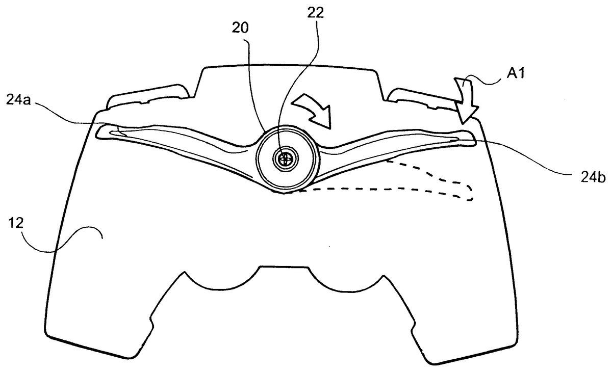
DETAILED DESCRIPTION OF PREFERRED EMBODIMENTS Referring to FIG. 1 a - 1 c , there is shown a game controller 10 according to a first embodiment of the invention. Game controller 10 includes a housing 12 , a plurality of upper game controls 14 and a plurality of front control buttons 16 a - 16 d . A central axis 18 runs through game controller housing 12 transverse to the two-dimensional plane in which the D-pad or joystick operates. The aforementioned D-pad and/or joystick are included in the plurality of upper game controls 14 . In accordance with the present embodiment, a driving/steering lever 20 is disposed on the underside of the controller housing 12 and is rotatably mounted about a rotation axle 22 which is coaxially aligned with central axis 18 . Lever 20 is spring biased into a center position and includes two lever ends 24 a and 24 b positioned to be actuated by the fingers of the user's right and left hands, respectively. Lever 20 is variably actuated based on the degree of depression applied by the user. Referring to FIG. 1 c , when lever end 24 b is actuated in the direction indicated by arrow Al, the opposing end 24 a is displaced an equal amount in the direction A 2 (as shown by dotted lines in FIG. 1 c ). The variable position ability of lever 20 in addition to its ergonomic disposition on the underside of the controller allows the user to more accurately and realistically apply steering control in response to the video game being played. The rotating action of lever 20 enables the steering/driving control to be accurately and variably controlled while allowing the user to maintain both hands on the controller at all times. This further allows the user ...
DETAILED DESCRIPTION OF PREFERRED EMBODIMENTS
Referring to FIG. 1 a - 1 c , there is shown a game controller 10 according to a first embodiment of the invention. Game controller 10 includes a housing 12 , a plurality of upper game controls 14 and a plurality of front control buttons 16 a - 16 d . A central axis 18 runs through game controller housing 12 transverse to the two-dimensional plane in which the D-pad or joystick operates. The aforementioned D-pad and/or joystick are included in the plurality of upper game controls 14 .
In accordance with the present embodiment, a driving/steering lever 20 is disposed on the underside of the controller housing 12 and is rotatably mounted about a rotation axle 22 which is coaxially aligned with central axis 18 . Lever 20 is spring biased into a center position and includes two lever ends 24 a and 24 b positioned to be actuated by the fingers of the user's right and left hands, respectively. Lever 20 is variably actuated based on the degree of depression applied by the user. Referring to FIG. 1 c , when lever end 24 b is actuated in the direction indicated by arrow Al, the opposing end 24 a is displaced an equal amount in the direction A 2 (as shown by dotted lines in FIG. 1 c ). The variable position ability of lever 20 in addition to its ergonomic disposition on the underside of the controller allows the user to more accurately and realistically apply steering control in response to the video game being played. The rotating action of lever 20 enables the steering/driving control to be accurately and variably controlled while allowing the user to maintain both hands on the controller at all times. This further allows the user to actuate any of the upper 14 or front 16 controls during steering/driving action.
FIG. 5 a shows one example of the electronic implementation of lever 20 into game controller 10 . As shown a potentiometer 42 is connected to a printed circuit board 40 contained within housing 12 . Rotation axle 22 of lever 20 is connected to or integral with the stem of potentiometer 42 , and a spring 44 , wound around axle 22 and held in place by notches 46 a and 46 b , biases lever 20 into its central operable position. Thus, the actuation of either lever end 24 a or 24 b changes the resistance output of potentiometer 42 and thereby allows for the variable steering/driving adjustment of a video game being played through a connected game console (not shown).
FIGS. 2 a and 2 b show a second embodiment where steering lever 20 is separated into two independently operable parts consisting of lever ends 24 a and 24 b . In this embodiment, each lever end 24 a and 24 b is independent of the other. Thus, when lever end 24 b is depressed in the direction indicated by A 1 , lever end 24 a does not move. This embodiment requires additional control circuitry as shown in FIGS. 5 b and 9 a.
Referring to FIG. 5 b , there is shown an embodiment for the independent control and actuation performed by independent levers 24 a and 24 b . As shown, separate potentiometers 42 a and 42 b are connected to circuit board 40 and to the respective lever end 24 a and 24 b via a gear mechanism made up of gears 47 a and 47 b . Those of skill in the art will recognize that the rotation axle 22 must now be configured to allow each lever end 24 a and 24 b to rotate independently of each other. Axle 22 can be configured to have an inner axle 26 connecting lever end 24 a to potentiometer 42 a via gears 47 a and 43 a . Accordingly, an outer axle 28 connects lever end 24 b to potentiometer 42 b via gears 47 b and 43 b . The spring 44 can be positioned as shown and notches 46 a and 46 b are disposed accordingly to allow each lever end 24 a and 24 b to be spring biased in a desired direction or position. Thus, when one lever end 24 a or 24 b is actuated, the corresponding potentiometer 42 a or 42 b will change its resistance output in response to that movement and thereby allow the variable, and increased accuracy of driving control in the desired direction.
The embodiment shown in FIG. 5 b is one example of how such configuration may be implemented. Those of ordinary skill will recognize that various other methods for allowing the independent rotation and actuation may be implemented without departing from the spirit of the invention.
FIGS. 6 a and 6 b show another circuitry implementation operable for the embodiment depicted in FIGS. 1 a , 1 b and 1 c . In this embodiment, a pair of hall effect sensors 48 a and 48 b are connected to the circuit board 40 , and an opposing pair of magnets 49 a and 49 b are positioned on a holder 59 mounted to the axle 22 . Thus, when either of the lever ends 24 a or 24 b are moved, the positions of the magnets 49 a and 49 b are detected by the corresponding hall effect sensors 48 a and 48 b (i.e., based on the strength of the magnetic fields created by the magnets), and the corresponding electrical steering/driving command is generated and output to the connected game console (not shown).
FIGS. 3 a - 3 c show a third embodiment where steering lever 30 is a one piece lever that pivots about a centrally disposed pivot line P, transverse to central axis 18 . Steering lever 30 is spring biased and includes lever ends 32 a and 32 b that are actuated by the user engaging and pulling the lever end in the direction indicated by arrow A 3 . When lever end 32 b is engaged as shown in
FIG. 3 a , opposing end 32 a responds by moving in an opposite direction A 4 (shown in dotted lines). The pivotal action of lever 30 enables the steering/driving control to be accurately and variably controlled while allowing the user to maintain both hands on the controller at all times. This further allows the user to actuate any of the upper 14 or front 16 controls during driving action. FIGS. 4 a and 4 b show a modified embodiment where lever 30 is separated into two independently operable ends 32 a and 32 b , each being pivotal about pivot line P.
FIG. 7 shows the electrical implementation of the embodiments disclosed in FIGS. 3 a - 4 b . As shown, the lever arm 30 is connected to a pivot mount 50 by two legs 34 a and 34 b . The pivot mount 50 includes a pivot ball 52 pivoting upon a pivot indentation 53 within the controller housing, and magnets 49 a and 49 b arranged thereon. The pivot mount 50 , and thereby lever arm 30 , is biased into a center position by springs 36 a and 36 b . Corresponding hall effect sensors 48 a and 48 b are mounted on the circuit board 40 and are positioned so as to detect the movement of the respective magnets 49 a and 49 b and produce electrical control signals accordingly. In the independent arm operation embodiment of FIGS. 4 a and 4 b , the pivot mount 50 need not be separated into two parts, but rather the lever arm 30 separated into it's two lever ends 32 a and 32 b while retaining a flexible connection to prevent separation from each other. In this arrangement, the hall effect sensors 48 a and 48 b and magnets 49 a and 49 b will continue to operate as desired.
FIGS. 8 a and 8 b show another embodiment of the electronic implementation of lever 20 (made up of lever ends 24 a and 24 b ) into the game controller. As shown, lever ends 24 a and 24 b have interlocking teeth 64 a and 64 b , respectively, arranged around the rotation axle 22 . A cap or other securing mechanism 66 attached onto axle 22 and retains lever ends 24 a and 24 b in their operable position on the underside of the game controller. An arm or extension 60 is connected to rotation axle 22 and includes a sensor mechanism 62 for sensing the rotation motion of the lever ends 24 a and 24 b and providing output signals corresponding to the detected lever end movement. Sensor mechanism 62 is described later with reference to FIGS. 11 a - 11 c
FIGS. 9 a and 9 b show another embodiment of the electronic implementation of lever 20 (made up of lever ends 24 a and 24 b ) into the game controller. This embodiment is particularly suited for the independent operation of lever ends 24 a and 24 b , as discussed above with respect to the embodiments of FIGS. 2 a and 2 b . As shown, each lever end 24 a and 24 b includes a corresponding rotation shaft 23 a and 23 b having an arm or extension 61 a and 61 b , respectively. Extensions 61 a and 61 b carry part of the sensor mechanism 62 used to detect the rotation position of each lever arm 24 a and 24 b , respectively. As with the embodiment of FIGS. 8 a and 8 b , a cap or other device 66 secures the levers 24 a and 24 b in their operable positions and onto rotation axles 23 a and 23 b , respectively.
FIGS. 10 a - 10 c show an alternative embodiment for implementing the pivoting steering lever 30 (made up of lever ends 32 a and 32 b ) into the game controller. Accordingly, each lever end 34 a and 34 b is pivotally connected to the circuit board 40 or controller housing 12 via pivot shafts 70 a and 70 b , respectively. A hall effect sensor 48 a and 48 b is mounted on the circuit board 40 , with correspondingly mounted magnets 49 a and 49 b on the respective levers 32 a and 32 b ( FIGS. 10 a and 10 b ). FIG. 10 c shows an alternative embodiment where a pressure sensor 58 is connected to the circuit board 40 and operable to detect the pressure applied to the levers and output corresponding control signals from the game controller.
FIGS. 11 a - 11 c show various exemplary embodiments for the implementation of sensor mechanism 62 . FIG. 11 a shows the use of a hall effect sensor 48 mounted to the circuit board 40 and a correspondingly arranged magnet 49 carried by rotating extension 60 . FIG. 11 b shows the use of a light sensor 72 with light source 74 mounted on circuit board 40 . A slotted wheel 76 passes between the sensor 72 and light source 74 so as to provide the rotation detection capability required for the levers. FIG. 11 c shows another embodiment where a piezo sensor is mounted on the extension 60 and in electrical contact with the circuit board 40 .
Those of ordinary skill in the art will recognize that the implementation embodiments shown in FIGS. 5 a - 11 c are examples of such implementation and may be modified without departing from the spirit of the invention
While there have shown and described and pointed out fundamental novel features of the invention as applied to preferred embodiments thereof, it will be understood that various omissions and substitutions and changes in the form and details of the methods described and devices illustrated, and in their operation, may be made by those skilled in the art without departing from the spirit of the invention. For example, it is expressly intended that all combinations of those elements and/or method steps which perform substantially the same function in substantially the same way to achieve the same results are within the scope of the invention. Moreover, it should be recognized that structures and/or elements and/or method steps shown and/or described in connection with any disclosed form or embodiment of the invention may be incorporated in any other disclosed or described or suggested form or embodiment as a general matter of design choice. It is the intention, therefore, to be limited only as indicated by the scope of the claims appended hereto.
Claims
- A genre specific game controller comprising: a game controller housing adapted for two-hand operation;a plurality of game controls disposed on an upper side of said housing;and a steering lever disposed on an underside of said housing and having two lever ends each adapted to be actuated by one of a user's hands, said steering lever for receiving steering inputs from a user.
- The game controller according to claim 1 , further comprising electronic circuitry disposed within said housing for outputting variable electrical control commands corresponding to variable positions of said lever ends for controlling steering actions in a video game.
- The game controller according to claim 2 , wherein said electronic circuitry comprises a printed circuit board contained within said housing and a potentiometer electrically connected to the printed circuit board and having a shaft connected to said lever, said potentiometer producing the variable control commands corresponding to the detected movement of the lever.
- The game controller according to claim 2 , wherein said electronic circuitry comprises: a printed circuit board contained within said housing;a first and a second potentiometer electrically connected to the printed circuit board;and a gearing mechanism connecting said first potentiometer to one of said lever ends and said second potentiometer to the other of said lever ends, wherein said first and second potentiometers produce the variable control commands corresponding to the detected movement of the lever.
- The game controller according to claim 2 , wherein said electronic circuitry comprises: a printed circuit board contained within said housing;at least one hall effect sensor electrically connected to said printed circuit board;and at least one magnet connected to said lever and disposed proximate said at least one hall effect sensor, said at least one hall effect sensor producing the variable control commands corresponding to the detected movement of the lever.
- The game controller according to claim 2 , wherein said electronic circuitry comprises: a printed circuit board contained within said housing;a first hall effect sensor corresponding to one of said lever ends and connected to said printed circuit board;a second hall effect sensor corresponding to the other of said lever ends and connected to said printed circuit board;a first magnet disposed on said lever end corresponding to said first hall effect sensor;and a second magnet disposed on said lever end corresponding to said second hall effect sensor;wherein said first and second magnets move with the respective lever ends and said first and second hall effect sensors produce the variable control commands corresponding to the detected movement of the first and second lever ends.
- The game controller according to claim 2 , wherein said electronic circuitry comprises: a printed circuit board contained within said housing;a light source connected to said printed circuit board;a light sensor connected to said printed board and operable with said light source;and a slotted wheel disposed between said light source and said light sensor and connected to said lever, wherein actuation of said lever ends causes rotation of said slotted wheel such that said light sensor produces the variable control commands corresponding to the detected movement of the lever.
- The game controller according to claim 2 , wherein said electronic circuitry comprises: a printed circuit board contained within said housing;a piezo sensor connected to at least one of said lever ends and in electrical contact with said circuit board, said piezo sensor detecting movement of said lever ends and producing the variable control commands corresponding to the detected movement.
- A genre specific game controller comprising: a game controller housing being adapted for two-hand operation, said game controller housing having a central axis;a plurality of game controls disposed on an upper side of said housing, said game controls including a directional element operating in a two-dimensional horizontal plane transverse to said central axis;a steering lever having an axle and two lever ends each adapted to be actuated by one of a user's hands, said steering lever being disposed on an underside of said game controller housing such that said axle is aligned with said central axis, said steering lever for receiving steering inputs from a user;and electronic circuitry disposed within said game controller housing for detecting an operable position of said lever ends and outputting variable electrical control steering commands corresponding to the detected positions of said lever ends.
- The game controller according to claim 9 , wherein said electronic circuitry comprises a printed circuit board contained within said housing and a potentiometer electrically connected to the printed circuit board and having a shaft connected to said lever, said potentiometer producing the variable control commands corresponding to the detected movement of the lever.
- The game controller according to claim 9 , wherein said electronic circuitry comprises: a printed circuit board contained within said housing;a first and a second potentiometer electrically connected to the printed circuit board;and a gearing mechanism connecting said first potentiometer to one of said lever ends and said second potentiometer to the other of said lever ends, wherein said first and second potentiometers produce the variable control commands corresponding to the detected movement of the lever.
- The game controller according to claim 9 , wherein said electronic circuitry comprises: a printed circuit board contained within said housing;at least one hall effect sensor electrically connected to said printed circuit board;and at least one magnet connected to said steering lever and disposed proximate said at least one hall effect sensor, said at least one hall effect sensor producing the variable control commands corresponding to the detected movement of the lever.
- The game controller according to claim 9 , wherein said electronic circuitry comprises: a printed circuit board contained within said housing;a first hall effect sensor corresponding to one of said lever ends and connected to said printed circuit board;a second hall effect sensor corresponding to the other of said lever ends and connected to said printed circuit board;a first magnet disposed on said lever end corresponding to said first hall effect sensor;and a second magnet disposed on said lever end corresponding to said second hall effect sensor;wherein said first and second magnets move with the respective lever ends and said first and second hall effect sensors produce the variable control commands corresponding to the detected movement of the first and second lever ends.
- The game controller according to claim 9 , wherein said electronic circuitry comprises: a printed circuit board contained within said housing;a light source connected to said printed circuit board;a light sensor connected to said printed board and operable with said light source;and a slotted wheel disposed between said light source and said light sensor and connected to said lever, wherein actuation of said lever ends causes rotation of said slotted wheel such that said light sensor produces the variable control commands corresponding to the detected movement of the lever.
- The game controller according to claim 9 , wherein said electronic circuitry comprises: a printed circuit board contained within said housing;and a piezo sensor connected to at least one of said lever ends and in electrical contact with said circuit board, said piezo sensor detecting movement of said lever ends and producing the variable control commands corresponding to the detected movement.
Disclaimer: Data collected from the USPTO and may be malformed, incomplete, and/or otherwise inaccurate.