U.S. Pat. No. 6,652,384
IMAGE PROCESSING DEVICE FOR PLACING A PLAYER CHARACTER IN A VIRTUAL SPACE
Issue DateJune 11, 2001
Illustrative Figure
Abstract
No abstract is available for this record.
Description
DESCRIPTION OF THE PREFERRED EMBODIMENT Next, embodiments of the present invention will be explained in an example of a video game device. This video game device performs a new type of game program which combines a shooting game and a role-playing game, and further performs the processing step of a role-playing game and the processing step of a shooting game respectively. This game is performed within a virtual three-dimensional space defined in a game program. In the processing of a role-playing game, the character operated by the player (player character) moves on a certain movement map. The screen scrolls (meaning the screen moves in a fixed direction or the background moves within the screen) in the direction of the player character's movement on the game screen, and an image of the background etc. including the player character is displayed on the game screen. Within the virtual space, main characters such as the player character and enemy character are formed of polygons and the background is formed of a scroll screen. A virtual camera is set in a certain point within the three-dimensional space, and the image seen from this virtual camera is displayed on the game screen. If a certain encounter information occurs when the player character is moving on the movement map, the processing step of a role-playing game is transferred to the processing step of a shooting game. Encounter information used herein shall mean information or signals that order a game scene (e.g. role-playing scene) to transfer to another game scene (e.g. shooting scene). This encounter information is made to correspond with the encounter flag set in the RAM, thereby enabling the distinction of whether or not encounter information exists according to the 0 or 1 of the encounter flag. FIG. 1 shows a scene in which the ...
DESCRIPTION OF THE PREFERRED EMBODIMENT
Next, embodiments of the present invention will be explained in an example of a video game device. This video game device performs a new type of game program which combines a shooting game and a role-playing game, and further performs the processing step of a role-playing game and the processing step of a shooting game respectively. This game is performed within a virtual three-dimensional space defined in a game program.
In the processing of a role-playing game, the character operated by the player (player character) moves on a certain movement map. The screen scrolls (meaning the screen moves in a fixed direction or the background moves within the screen) in the direction of the player character's movement on the game screen, and an image of the background etc. including the player character is displayed on the game screen. Within the virtual space, main characters such as the player character and enemy character are formed of polygons and the background is formed of a scroll screen. A virtual camera is set in a certain point within the three-dimensional space, and the image seen from this virtual camera is displayed on the game screen.
If a certain encounter information occurs when the player character is moving on the movement map, the processing step of a role-playing game is transferred to the processing step of a shooting game. Encounter information used herein shall mean information or signals that order a game scene (e.g. role-playing scene) to transfer to another game scene (e.g. shooting scene). This encounter information is made to correspond with the encounter flag set in the RAM, thereby enabling the distinction of whether or not encounter information exists according to the 0 or 1 of the encounter flag.
FIG. 1 shows a scene in which the player character 200 A (image of a dragon) operated by the player is moving on the movement map at the time of performing the role-playing game. 12 A is the locus of the flight path of player character 200 a. 100 A is an enemy character existing on the movement map. The player may freely operate the direction key of the controller, as will be explained hereafter, and freely set the flight direction and flight range of the player character 200 A within the virtual space. Furthermore, there are situations wherein the enemy character will not be displayed on the movement map.
FIGS. 2 and 3 are battle scenes at the time of performing the shooting program. FIG. 2 is a battle scene with an enemy character that does not move, and FIG. 3 is a battle scene with an enemy character 100 A that moves. In the battle scene shown in FIG. 3 , a path 16 A is set on the field and the dragon and enemy character move along this path 16 A by compulsory scroll.
Although no path exists in FIG. 2 and compulsory scroll will not be performed, on the other hand, the player character 200 A may fly freely around the enemy character. This battle scene is continued until the battle between the enemy character 100 A and player character 200 A is completed.
If an event (e.g. the player character 200 A encounters the enemy character 100 A) occurs while moving on the movement map, the encounter flag is set to 1 and proceeds to a battle scene. In this battle scene, real-time shooting is possible. In the battle scene of FIG. 3 , a game which simulates position taking among a plurality of enemy characters and the player character 200 A is possible, as will be explained hereafter. Position taking used herein shall mean such acts of the player character 200 A escaping to a safe position in advance by predicting the attacking direction of the enemy character 100 A, or the enemy character chasing the player character 200 A, thus, any acts in which the enemy character 100 A or player character 200 A taking an advantageous position for battling.
As mentioned above, the transfer from the role-playing scene to the shooting-scene starts at the time encounter information occurs. Let it be assumed that encounter information occurred when 1 has been set in the encounter flag.
FIG. 4 is a flowchart showing the relationship between role-playing game processing (movement map processing) and shooting game processing (battle scene processing). This flowchart is performed by the CPU of a video game device having a hardware structure which will be explained hereafter.
Foremost, when the game begins, a movement scene (e.g. scene of FIG. 1 ) as one scene of a role-playing game is displayed on the game screen (S 4 . 0 ).
In S 4 . 2 , the encounter flag is checked, and proceeds to battle scene processing if the encounter flag is 1. If the encounter flag is 0, it returns to S 4 . 0 . This encounter f lag is a flag for proceeding to the battle scene, and a shooting scene is proceeded in the respective battle scenes. These battle scenes may be made the same or different. When the above encounter flag is set to 1 or a random encounter occurs, it proceeds to S 4 . 8 , and when an event encounter occurs, it proceeds to S 4 . 6 .
This event encounter is caused when a certain event occurs, such as when the player character 200 A encounters the enemy character 100 A on a flight path as shown in FIG. 1 . Furthermore, when displaying the enemy character 100 A on the movement map, the player may control the flight direction of the player character 200 A in order to avoid the player character 200 A from encountering the enemy character 100 A. On the other hand, a random encounter is caused when a certain condition materializes or occurs, such as when a certain time has elapsed or when the game score reaches a certain value.
In S 4 . 10 , it is judged whether or not the battle scene has finished. It returns to the movement scene if the battle is finished, and returns to the battle scene if the battle is not finished.
In the event battle scene (S 4 . 6 ) and random battle scene (S 4 . 8 ), a real-time shooting game in which the player character 200 A and enemy character 100 A start attacking or avoid being attacked etc. is reproduced. As an example of this battle scene, for example, there are the types shown in FIGS. 2 and 3 . In FIG. 3 , by compulsorily making the player character 200 A fly along a certain path (route) 16 A, the player may easily control the player character 200 A in the processing step of a shooting game. In other words, as the player character is compulsorily made to fly on the path 16 A, the player may concentrate on the shooting game. Furthermore, as the path 16 A is made to adequately curve and pass through various backgrounds (mountains, valleys), the path 16 A is therefore not boring. Defining this type of path 16 A is possible by a certain coordinate point passing through a world coordinate system in a virtual three-dimensional space.
The battle scene is over when all of the enemy characters 100 A are eliminated, when the player character 200 A is eliminated, or when the game is finished compulsorily (reset), etc. The destruction of the enemy character 100 A and player character 200 A is performed as follows. The collision between the polygons forming the enemy character 100 A or player character 200 A and the polygons forming the virtual weapons (e.g. bullets) is judged, and when this judgment is affirmed, the shape of the polygons forming the enemy character 100 A or player character 200 A is modified, thereby causing changes in the character condition value. When this condition value exceeds a certain value, the enemy character 100 A and player character 200 A are eliminated.
Incidentally, in the flowchart shown in FIG. 4 , S 4 . 0 and S 4 . 2 are equivalent to the processing step for a role-playing game, and the processing on and after S 4 . 4 are equivalent to the processing step of a shooting game.
Next, the structure of the game device hardware will be explained. FIG. 5 is an external perspective view of the game device. In this diagram, numeral 1 is the main game device. At the front of this main game device 1 , a pad 2 b for operation is connected to a connector 2 a via a cable 2 c . Moreover, at the top portion of this main game device 1 , a cartridge interface (cartridge I/F) 1 a for connection to a ROM cartridge is provided. Similarly, a CD-ROM drive 1 b for reading a CD-ROM is provided at the top portion of the main game device 1 . At the back of the main game device 1 , a video output terminal and an audio output terminal (not shown) are provided. This video output terminal is connected to a video input terminal of a TV receiver 5 via a cable 4 a . On the other hand, the audio output terminal is connected to an audio input terminal of the TV receiver 5 via a cable 4 b . In this type of game device, by operating the pad 2 b , a user may play a game by operating the player character while watching the image displayed on the TV receiver 5 .
FIG. 6 shows a functional block diagram of the game device hardware. The main game device is structured of a CPU block 10 for controlling the entire device, a video block 11 for controlling the display of a game screen, a sound block 12 for generating sound effects or the like, a subsystem 13 for reading a CD-ROM, and other elements.
The CPU block 10 is structured of an SCU (System Control Unit) 100 , a main CPU 101 , a RAM 102 , a ROM 103 , a cartridge I/F 1 a, a sub CPU 104 , a CPU 105 , and other elements.
The main CPU 101 is for controlling the entire device. This main CPU 101 comprises on the inside an operating function similar to a DSP (Digital Signal Processor) and is able to perform application software at high speeds. Furthermore, based on peripheral data received from the sub CPU 104 , the main CPU 101 controls image of, for example, rotational conversion and perspective conversion of characters in the virtual space and performs processing to display such image on the screen.
The RAM 102 is used as a work area of the main CPU 101 . The ROM 103 has, for example, an initial program for initialization processing written thereon. The SCU 100 is able to perform smooth input and output of data between, for example, the main CPU 101 , VDPs 120 and 130 , and the DSP 140 by controlling buses 105 , 106 and 107 .
Moreover, the SCU 100 comprises a DMA controller therein and is capable of directly transmitting character data (polygon data) during a game to the VRAM 121 within the video block 11 . By this, performing a game program at a high speed is possible. The cartridge I/F 1 a is for reading in the game program supplied in a form of a ROM cartridge to the RAM 102 .
The sub CPU 104 is the so-called SMPC (System Manager & Peripheral Control) and is provided with a function of automatically recognizing the type of peripheral connected to the connector 2 a and gathering peripheral data or the like in a communication format according to the type of peripheral. This connector 2 a may be connected to an optional peripheral among a pad, a joystick, a keyboard and the like.
The video block 11 comprises a first VDP (Video Display Processor) 120 which overwrites characters composed of polygon data onto the background and generates image, and a second VDP 130 which performs drawing of background image, as well as synthesis and clipping of polygon image data and scroll image data based on priority.
The first VDP 120 has a built-in system register 120 a and is connected to the VRAM 120 and frame buffers 122 and 123 . Polygon image data displaying the characters are sent to the first VDP 120 via the main CPU 101 , and is drawn on the frame buffer 122 (or 123 ) for drawing, for example, in a 16 bits/pixel or 8 bits/pixel format. Data drawn on the frame buffer 122 (or 123 ) is sent to the second VDP 130 at the time of the displaying mode.
Like this, the frame buffer uses buffers 122 and 123 and has a double buffer structure which switches between drawing and display for each frame. Moreover, regarding information for controlling the drawing, the first VDP 120 controls the drawing and display according to the instructions set in the system register 120 a of the first VDP 120 from the main CPU 101 via the SCU 100 .
On the other hand, the second VDP 130 has a built-in register 130 a and a color RAM 130 b , and is connected to a VRAM 131 . Furthermore, the second VDP 130 is connected to the first VDP 120 and the SCU 100 via the bus 107 , as well as to the video output terminal Vo via the memory 132 and the encoder 160 . The video input terminal of the TV receiver 5 is connected to the video output terminal Vo via the cable 4 a.
Scroll image data is defined in the VRAM 131 and the color RAM 130 b from the main CPU 101 via the SCU 100 . Information for controlling a display screen is similarly defined in the register 130 a . Data defined in the VRAM 131 is read-out according to the contents set in the register 130 a from the second VDP 130 , and is converted to image data of each scroll image displaying the background against the character. The priority of image data of each scroll image and image data of the polygon data sent from the first VDP 120 is decided according to the setup in the register 130 a , whereby being synthesized into a final displaying image data.
If this displaying image data is in a palette format, color data defined in the color RAM 130 b is read-out and displaying color data is generated. Moreover, if the displaying image data is in an RGB format, displaying image data itself will be the displaying color data. This displaying color data is output to an encoder 160 after being stored in a memory 132 . The encoder 160 generates image signals by adding synchronization signals or the like to this image data and supplies the same to the video input terminal of the TV receiver 5 via the video output terminal Vo. Like this, a game image is displayed on the screen of the TV receiver 5 .
The sound block 12 comprises a DSP 140 for synthesizing sound according to a PCM format or a FM format, and a CPU 141 for, for example, controlling the DSP 140 . Sound data generated by the DSP 140 are converted to two-channel signals by a D/A converter 170 and supplied to an audio output terminal Ao via an interface 171 thereafter. This audio output terminal Ao is connected to the audio input terminal of the TV receiver 5 via the cable 4 b . Therefore, sound signals are input into an audio amplification circuit (not shown) from the audio input terminal of the TV receiver 5 via the audio output terminal Ao and the cable 4 b . Sound signals amplified in the audio amplification circuit drives the speakers 5 a and 5 b built inside the TV receiver 5 .
The subsystem 13 is structured of a CD-ROM drive 1 b , a CD-I/F 180 , a CPU 181 , an MPEG-AUDIO portion 182 , MPEG-VIDEO portion 183 , and other elements. This subsystem 13 has functions, for example, to read-in application software supplied in a CD-ROM form and to reproduce animation. The CD-ROM drive 1 b is for reading-in data from a CD-ROM. The CPU 181 performs processing such as for controlling the CD-ROM drive 1 b and correcting errors in the read-in data. Data read-in from a CD-ROM are supplied to the main CPU 101 via the CD-I/F 180 , the bus 106 and the SCU 100 , and are used as application software.
Furthermore, the MPEG AUDIO portion 182 and MPEG VIDEO portion 183 are devices for restoring data which are compressed in MPEG (Motion Image Expert Group) standards. If the restoration of the MPEG compressed data written on a CD-ROM by using the MPEG AUDIO portion 182 and MPEG VIDEO portion 183 is performed, reproduction of animation will become possible.
The game device explained herein is structured to perform processing so as to simulate an easy operation for the player while maintaining the amusement of the game. Various workings of this game machine will be explained hereafter.
FIGS. 7 and 8 are diagrams showing the position relationship of the player character 200 A and enemy character 100 A in the battle scene shown in FIG. 3 .
The player character 200 A may move around the enemy character 100 A as well as move in an upward and downward direction. The player character 200 A moves along the arrow of path 16 A within the virtual space as shown in FIG. 3 . The player character 200 A may move around the enemy character while moving up and down in accordance with the movement of the enemy character 100 A.
That is, FIG. 8 specifically shows the movement range of the player character 200 A, showing that the player character 200 A may move within the cylindrical field (hereinafter referred to as the movement area ) 202 set around the enemy character 100 A.
Moreover, it may be set so that the enemy character 100 A is to move around the player character 200 A. Furthermore, in FIG. 3 , it may also be set so the enemy character 100 A is to move along the arrow of the path 16 A during a battle scene.
The enemy character 100 A attacks the player character 200 A in a variety of ways either randomly, or in a certain pattern. The player predicts the movement of the enemy character 100 A and operates the player character 200 A within the movement area 202 , and further attacks the enemy character 100 A while avoiding the attacks made by the enemy character 100 A. If the player character 200 A is able to fatally damage the enemy character 100 A within a certain time, the game is won, whereas if the player character 200 A receives fatal damage, the game is over.
By setting a movement area 202 such as this, there are the following advantages. By limiting the movement range of the player character 200 A within this field, the player character 200 A may be easily placed in the vicinity of the enemy character 100 A. Moreover, the player character 200 A may take an advantageous position against the enemy character 100 A.
FIG. 34 is a flowchart for controlling the placement of the player character 200 A and is repeatedly performed by the CPU when a battle scene like the one shown in FIG. 3 begins until such battle scene is finished. In S 34 . 0 , the position of the enemy character 100 A is detected. In S 34 . 2 , the shape (e.g. diameter and height of the cylinder) of the movement area 202 is decided. In S 34 . 4 , the movement area is set so that the enemy character 100 A is placed in the center of the movement area 202 . In other words, the movement area 202 is formed with the enemy character in the center and is moved along the path 16 A (c.f. FIG. 3 ) together with the enemy character 100 A.
The decision of the radius and height of the movement area 202 in S 34 . 2 is performed as follows. For example, as shown in FIG. 9 , the radius of the movement area 202 is enlarged when the enemy character becomes a large form(polygon). Therefore, the CPU reads-in each vertex coordinates of polygons forming the enemy character within the virtual space and decides the size of the enemy character 100 A from the difference between the maximum coordinates and minimum coordinates in each direction of XYZ. It is further possible to have the form of the movement area 202 certain for each enemy character 100 A.
By operating the pad 2 b , the player may continuously move the player character 200 A in a direction toward the height of, or the circumferential direction of the cylinder of the movement area 202 with a cylindrical shape. Especially, by dividing the cylindrical movement area 202 in a plurality of blocks (e.g. four blocks), the operation of the player character 200 A could be made easy when moving the player character 200 A in a circumferential direction of the cylinder. When dividing the movement area 202 into four blocks, such division may be made by two rectangular surfaces ( 500 and 502 ) which directly cross each other. Moreover, these rectangular surfaces are for showing how to divide the field 202 , and such rectangular surfaces are not actually provided.
The movement of the player character 200 A may be positioned in the center of each block. This point is explained with reference to FIG. 35 . When moving the player character 200 A from a certain block composing the cylindrical movement area 202 to another block, it shows that the player character 200 A will move from a certain point 350 within the block to a certain point 352 within another block. In such case, after having moved to a certain point, the player character 200 A may either move up, down, left or right along the surface of the block or be designed to not move at all within such block.
The movement of the player character 200 A between the blocks, for example, is as follows. The four divided blocks are made to correspond with the cross key. For example, when the upward direction key of the cross key is operated, the player character 200 A is moved to a block positioned in the progressing direction of the player character 200 A. When the downward direction key is operated, the player character 200 A is moved to a block in the back, when the right key is operated, is moved to the right block, and when the left key is operated, is moved to the left block. Moreover, the upward and downward keys may be designed to correspond to the movement in the direction toward the height of the cylindrical movement area 202 .
The player character 200 A may be designed to move not only on the surface of the movement area 202 , but also on the inside as well.
The main CPU reads-in the game program supplied from a medium such as a cartridge I/F or a CD-ROM. In accordance to this game program, a bullet is fired from the enemy character 100 A toward the player character 200 A. If the player character 200 A is hit with this bullet, an image of the player character being eliminated or destroyed generated. Whereas if the player character 200 A is not hit with this bullet, an image which shows the player character being damaged is not generated.
FIG. 10 is a model diagram of such image. FIG. 10 is equivalent to a plan view of FIG. 8 . Firing of the bullets from the enemy character 100 A is separately performed in each of the four blocks of front, back, left and right (any one of blocks A 1 through A 4 of FIG. 8 ).
FIG. 10 shows the situation where a bullet is being fired within the block 206 by the enemy character 100 A. If the player character 200 A is within this block, the possibility of being hit will become high. On the other hand, if the player character 200 A is within the block 208 , there is no possibility of being hit. The enemy character 100 A has a virtual weak point field (weak point collision) 207 . By moving the player character 200 A around to the weak point collision 207 , an effective attack against the enemy character 100 A may be performed.
As mentioned above, the firing direction of bullets from the enemy character is set for each of the four blocks. The bullet is either fired by drawing a straight line in a certain direction or by drawing a certain route. Accordingly, the player may predict the direction of the fired bullet and be prepared.
As for the type of bullets, there are light beams, guidance bullets, and various other types. The CPU decides such type of bullet and its flight route in response to the program. Like this, various types of flight routes of bullets exist.
The player character 200 A moves to any one of the four blocks in order to avoid being hit by the bullet fired from the enemy character 100 A or to effectively attack the weak point of the enemy character 100 A.
By providing rules as to the firing direction of the bullet, the bullet path, type of bullet, and firing timing etc., the player may understand these rules by playing the game and will be able to predict the likes of the bullet route. Based on this prediction, the player may select an area where the bullet will not reach and avert the player character in advance.
FIG. 11 shows a battle screen displaying a virtual radar 11 A at the upper right portion of the screen. This virtual radar 11 A is for clearly showing the player the position of the player character 200 A against the enemy character 100 A. On this virtual radar 11 A, a symbol 200 B of the player character 200 A and a symbol 100 B of the enemy character 100 A are displayed. Therefore, the relative position relationship between the enemy character 100 A and player character 200 A may be known by this virtual radar 11 A.
As it is clear from the virtual radar in FIG. 11 , the player character 200 A is placed in a block that is in front of the enemy character 100 A. In such case, by differentiating the color of the block in which the symbol 200 B of the player character 200 A exists with the background image, the player will be able to know the position relationship between the player character 200 A and the enemy character 100 A at a glance.
In FIG. 11 , numeral 110 is a gauge for showing the player that the player character 200 A is in an attacking condition. By this gauge reaching the maximum value, the player is able to use a desired weapon and make the player character 200 A attack the enemy character 100 A. The present invention provides a characteristic processing in relation to this gauge. This point will be explained hereafter.
Moreover, the numerical value 10 in the vicinity of the enemy character 100 A displays the damage of the enemy character 100 A. HP is called a hit point and expresses the remaining life of the player character with the numerical value of the numerator over the denominator. The numerator is the present remaining HP and the denominator is the maximum HP. Furthermore, BP is called a berserk point and shows points of the remaining strength for the player character 200 A to produce techniques against the enemy character 100 A. A technique is, for example, equivalent to magic or a deathblow in the program.
Regarding the movement form of bullets, there exists a plurality of forms such as the bullet being fired in order from front, back, left and right, or being fired in a timing of the changes of certain movements (vibrations or alterations) or forms (size, shape, color) of the enemy character 100 A. Here, a bullet is equivalent to a moving character according to the claims.
FIG. 12 shows a flowchart for the CPU 101 to achieve predicting processing of attacks. This flowchart is structured of, and may be largely divided into, a phase F 1 for selecting the movement area 202 of the player character 200 A and the attacking weapon against the enemy character 100 A and a phase F 2 for determining the result of the attack between the player character 200 A and enemy character 100 A. These phases are repeatedly performed for every one interruption.
The result of the selection of the movement area is input to the game device by the player's operation of the pad 2 b (S 600 ). The player makes this selection by predicting the fired direction or timing of the enemy bullet, or the weak point of the enemy character 100 A. According to this input result, the CPU places the player character in the selected block.
Next, in S 602 , the player selects a weapon. According to the type of weapon which was selected, a target cursor displayed toward the enemy character 100 A is displayed on the screen as will be explained hereafter. In such case, the form of the cursor may be changed according to the type of weapon that was selected.
For example, as to be shown in FIG. 18 hereafter, the shape or size of the displayed target cursor may be changed according to the type/power of the selected weapon. In such case, to show that the power is stronger if it is closer to the target cursor, the cursor may be changed to such shapes as (1) a large square, (2) a small square, (3) a large circle, (4) multiple squares, or (5) multiple circles. By placing the enemy character 100 A within this target cursor and pulling the trigger, the attack against the enemy character 100 A will be successful. The attack is achieved by operating a certain button of the pad 2 b.
In S 604 , the player character 200 A is mapped within one of the selected blocks (c.f. FIG. 8 ) according to the result of the selected movement area 202 , a target is displayed according to the type of weapon that was selected, and a image of a bullet fired from the enemy character 100 A is formed.
Here, the movement form of bullets such as the firing direction or type of bullet is decided among the various types by the CPU 101 according to the application software. The CPU 101 may be designed to automatically move the player character 200 A in the selected movement area. Moreover, the player may move the player character 200 A to the movement area 202 by the direction key of the pad 2 b.
Next, in step 606 , it is determined whether this prediction was correct or incorrect. That is, in the same step, the contact between the bullet and the player character 200 A will be judged (judgment of the overlap of coordinates in the virtual space) negative if the prediction was correct and positive if the prediction was incorrect.
If the prediction was incorrect, the damaged amount toward the player character 200 A is added in S 608 . If the damage of the player character 200 A exceeds a certain value, the player character 200 A is eliminated and a new player character 200 A appears (S 610 and S 612 ), and proceeds to S 614 if the damage is less than a certain value.
S 614 is a step that is selected when the result of the prediction was correct in S 606 . In S 614 , by a method of contact judgment, it is judged as to whether or not the attack from the player character 200 A to the enemy character 100 A was successful. When this judgment is affirmed, damage adding processing is performed to the enemy character 100 A, and processing such as damaging the enemy character 100 A, eliminating the enemy character 100 A, or making a new enemy character 100 A appear is performed (S 616 ).
On the other hand, if the judgment is denied in S 614 , it skips S 616 and returns. Moreover, if the damage judgment of the player character 200 A in S 610 is less than a certain value, it proceeds to S 614 .
Moving means and deciding means according to the claims are realized by S 604 . Predicting means according to the claims is realized by S 600 . Character position setting means according to the claims is realized by S 604 . Controlling means for displaying processing according to the claims is realized at the steps on and after S 606 .
In this embodiment, an example of the firing of bullets by the enemy character being controlled by the CPU of the game device was explained; however, it may also be controlled via the pad 2 b by the other player (the opponent). In such case, the movement form of bullets may be selected randomly at the opponent's will, and thereby, the player must predict the opponent's will to control the destination of the player character.
According to the game device shown in this embodiment, if the player predicts the bullet firing form of the enemy character 100 A and operates the pad 2 b according to such prediction, the player may move the player character 200 A to a certain position. If operated well, the bullet may be avoided. Therefore, even within a virtual three-dimensional space, the player character 200 A may be easily controlled in order to avoid the bullets and the like.
If the movement area 202 is selected, a certain flag is set for each block and temporarily stored in the RAM and the CPU is able to map the player character 200 A to a corresponding block by looking at such flag. Furthermore, by the player moving the player character 200 A up, down, left or right within the movement area 202 , the bullet fired from the enemy character 100 A toward the player character 200 A may be avoided.
The above was the explanation of changing the form of the cursor according to the selected weapon. Next, the case wherein selecting a return bullet (a return bullet to counter attack the enemy bullet) for defending the attack from the enemy character 100 A is explained.
FIG. 13 is a diagram wherein the enemy character 100 A is firing bullets toward the player character 200 A. In this diagram, the player character 200 A is positioned in front of and facing the enemy character 100 A. FIG. 13 ( 1 ) is the plan view of this condition and FIG. 13 ( 2 ) is the side view. The route of these bullets may take a plurality of forms.
Toward the player character 200 A, there are the likes of a straight bullet aiming at the top of the player character 200 A, a straight bullet aiming at the bottom, a curve bullet directed from the top toward the bottom, a curve bullet directed from the bottom toward the top, a curve bullet curving from the right toward the left, and a curve bullet directed from the left to the right, etc.
The player character 200 A fires an own return bullet to eliminate the enemy bullet before reaching the player character 200 A so that the bullet from the enemy character 100 A does not hit the player character 200 A. In this second embodiment, such game image is displayed on the game screen.
On the game screen, an image from the viewpoint of the virtual camera of the player character 200 A facing the enemy character 100 A is displayed. FIG. 14 shows the shape of the cursor for counter attacking from the side of the player character 200 A to be displayed on the game screen. This cursor is a double display of C 1 and C 2 .
If the player adjusts and moves this cursor to the enemy bullet and operates the pad 2 b , the return bullet is fired toward the position adjusted by the cursor. If the cursor is adjusted to the enemy bullet and the firing timing of the return bullet is appropriate, an image of the enemy bullet being eliminated by the return bullet is simulated.
If the cursor cannot be adjusted to the enemy bullet, this counter attack is judged as a failure. As the movement of the enemy bullet is fast, it is usually difficult to adjust and move the cursor to the enemy bullet. The key is to predict the course of the enemy bullet and the type of enemy bullet in advance and set the position of the cursor according to the result of such prediction. This point will be explained hereafter.
If the enemy bullet is captured by the cursor C 1 , destruction of the enemy bullet is possible, and especially if it is captured by the cursor C 2 , the destruction of the enemy bullet will be achieved with more certainty. The cursor C 2 is displayed in roughly a certain size in the center of C 1 . Moreover, this cursor is also a character according to the claims.
FIG. 15 is a diagram showing the movement range of the cursor with one-point chain lines. A 1 through A 4 show the range of the cursor setting position. Seen from the player, A 1 is to the upper right, A 2 is to the lower right, A 3 is to the upper left and A 4 is to the lower left. The player predicts the passing position (passing course) of the enemy bullet before the enemy bullet is fired, and sets the cursor destination to either one of A 1 through A 4 .
That is, the cursor position is adjusted to put the enemy bullet within the cursor C 2 . For example, if the prediction is correct, it should be easy to put the enemy bullet within the cursor C 1 . On the other hand, the above will be difficult if the prediction is incorrect. If the prediction is incorrect, for example, and the cursor is moved from the position of A 1 to the position of A 4 to put the enemy bullet within the cursor, it will be difficult to make the cursor follow the enemy bullet which is moving at a high speed because the moving distance of the cursor is far. If the cursor cannot be adjusted to the enemy bullet, the player character 200 A will be damaged by such enemy bullet.
Next, the significance of the cursor C 2 will be explained. Even if the flight route of the enemy bullet coincided with the prediction, if the type of bullet is different, the form in which the enemy bullet passes within the cursor C 1 will differ. For example, although it would be easy to put the enemy bullet within the cursor C 2 if the enemy bullet is a straight bullet, if the enemy bullet was a curve bullet, it may be possible to put the enemy bullet within the cursor C 1 but difficult to put it within the cursor C 2 . Therefore, if it is a curve bullet, the player may compete to eliminate the bullet with certainty by carefully adjusting the cursor so that the enemy bullet is put within the cursor C 2 . Nonetheless, this cursor C 2 may be omitted.
FIG. 16 shows an example of the forms of the cursor C 2 . The player predicts whether the enemy bullet is a straight bullet or a curve bullet. If predicted to be a curve bullet, the flight path of the curve bullet is further predicted. The form of the cursor C 2 is set according to the results of such prediction. The cursor shown in FIG. 16 ( 5 ) is the cursor when the player predicts a straight bullet. All four sides of this cursor are the same width. Of course, the square may be changed to a circle. The form of the cursor C 1 may also be made to be the same.
FIG. 16 ( 1 ) shows a cursor C 2 for corresponding to a curve bullet curving from the bottom toward the top as seen from the player (i.e. seen from the virtual camera on the side of the enemy character 100 A of the player character 200 A shown in FIG. 7 ). Similarly, the following are the respective cursor C 2 s corresponding to the curve bullet: FIG. 16 ( 2 ) is from top to bottom, FIG. 16 ( 3 ) is from left to right, and FIG. 16 ( 4 ) is from right to left.
If the cursor is widened in the direction of the curve, the enemy bullet may be more effectively put in the cursor C 2 when the prediction of the curve of the enemy bullet was correct, and thereby, the enemy bullet may be eliminated with certainty.
FIG. 17 is a flowchart of judging processing of the overlap of the cursor and the enemy bullet. At S 1100 , it is judged as to whether or not the enemy bullet was captured within the cursor C 1 . At S 1102 , it is further judged as to whether or not the enemy bullet was captured within the cursor C 2 . At S 1104 and S 1106 , it is judged as to whether the firing timing of the return bullet was appropriate.
If the firing timing at S 1104 was appropriate, an image of the enemy bullet being eliminated is generated at S 1108 . The probability of the enemy bullet being eliminated at this time is high. The same image is generated when the judgment is affirmed at S 1106 . The probability of the enemy bullet being eliminated at this time is lower than that of S 1108 .
If the judgment of S 1104 and S 1106 is denied, the counter attack will be judged as a failure and the enemy bullet will not be eliminated (S 1112 ). If no counter attack is made from the player side, the judgment of S 1104 and S 1106 will also be denied. Moreover, if the enemy bullet could not be captured within the cursor C 1 at S 1100 , it will also be judged as the enemy bullet not being eliminated.
In this embodiment, as the flight route etc. of the enemy bullet is predicted and a certain position of the cursor (target) for counter attacking is set according to the result of such prediction, a similar effect as embodiment 1 may be achieved.
Furthermore, in the phase F 1 of selecting the area and weapon of FIG. 12 , since the attacking direction, type, or characteristic of the enemy bullet is unknown, a game strategy from a new perspective of predicting the characteristic of the enemy bullet separately from, or together with the area selection and preparing for such bullet may be produced. In such case, the enemy bullet is a moving character that moves on the game screen.
Moreover, according to the above mentioned embodiment, by providing time to correspond to the prediction of the enemy attack and the player predicting the action of the enemy within such time and deciding such prediction by one's own experience, the strategy of the game will be diversified.
In addition, the shape of the cursor may further be changed according to the type of return bullet from the player character 200 A. Thereby, an effective return bullet may be predicted for eliminating the enemy bullet. Since this prediction factor is added, the game will be diversified and a high level game environment may be constructed.
In the phase F 1 of FIG. 12 , the CPU will not accept the input of bullet firing etc. from the player and only the reproduction of results of the selection of the movement area and weapon at S 600 through S 604 is performed by the CPU.
Accordingly, as it is clear from the characteristic of a role-playing game, during this phase, the player will know that input is not possible from the player's side by displaying, for example, a cinema scope (trademark). FIG. 19 shows the situation where the cinema scope is displayed on the screen. This cinema scope functions as notification means for showing the player that input by the pad 2 b is not possible.
The cinema scope shown in FIG. 19 is also information communicating means for stopping the progress of the clock in a real-time battle scene, and for informing the player that it is not possible to input to make the player character 200 A perform techniques or attack the enemy character 100 A. According to the screen of the cinema scope, the player is able to know that it is not possible to input for a certain period of time from the real-time battle scene. For example, FIG. 19 is an image of the enemy character 100 A attacking the player character 200 A in which processing of the player character being hit is performed. While this image is displayed, the progress of the time is stopped, and is made so that the attack from the player character may not be performed for a fixed time.
The cinema scope shown in FIG. 19 limits the image displayed on the game screen to a certain field on the TV monitor, for example, within a rectangular frame. At such time, an image of the game screen is not displayed outside of the rectangular frame, and for example, black wallpaper is displayed. Regarding the color of this wallpaper, the wallpaper of the cinema scope when the player side is attacking may be set to a blue color, and the wallpaper of the cinema scope when the enemy side is attacking may be set to a red color. Like this, by changing the color of the wallpaper of the cinema scope, the player will know whether the condition of not being able to input is due to the player's own attack or due to the enemy attack. However, the color of the wallpaper of the cinema scope is not limited to the above example, and may be of any color as long as the condition of not being able to attack due to either the player or the enemy may be distinguished.
Moreover, other than the display of the cinema scope shown in FIG. 19 as to limit the image of the game screen to a rectangular field on the TV monitor, it may also be limited to such as an oval field, an oblong field, or a circular field. In addition, an adequate narration or the player's lines may be displayed on the wallpaper according to the progress of the game.
Furthermore, in a role-playing game, the player side move and the enemy side move exist. Therefore, the steps such as phase F 1 on the player character side and phase F 2 on the player character side, phase F 1 on the opponents side, phase F 2 on the opponents side, phase F 1 on the player character side etc., the flowchart of FIG. 12 may be divided into the steps of the player character side and the enemy side.
Furthermore, prediction as used in the present specification is of course the player or the opponent's will, but if the game device is the player character side and the player is the enemy character side, it will be the prediction of the game device. Moreover, prediction includes, for example, when a player has a positive will for avoiding the enemy attack (above movement between the blocks of the movement area), has a positive will for eliminating the enemy attack (counter attacking the enemy bullet), or when the character position and cursor position are appropriately decided, and as a result, the attack made by the enemy character was able to be avoided.
Next, characteristic workings of the game device in battle scenes will be explained. FIG. 20 is a model diagram (an image from a battle scene) for explaining such characteristic workings. The part where the player character 200 A can attack the enemy character 100 A is defined as the collision point, and the player character 200 A attacks the enemy character 100 A by locking on the publicly known lock-on cursor LC to such collision point in a shooting game.
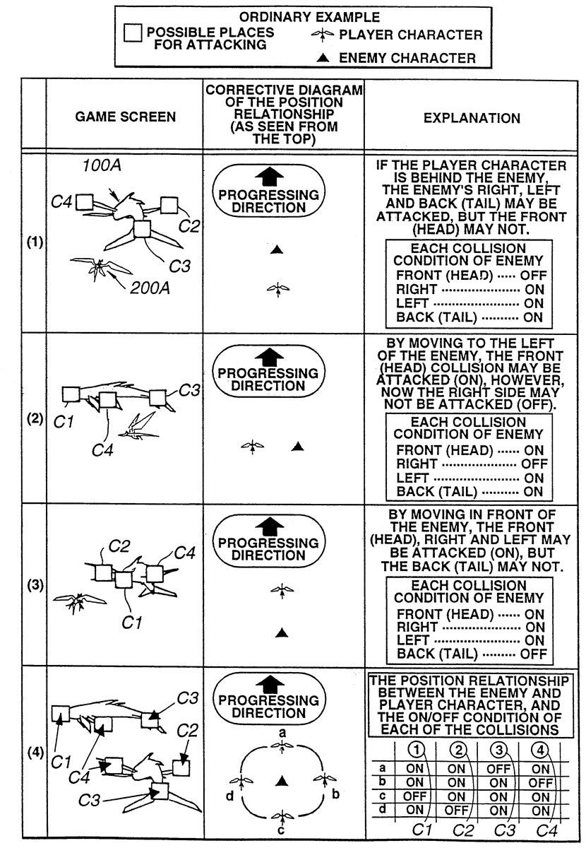
Collision used herein shall mean the contact (coincidence or overlapping of both coordinates) between a character in a game program, such as a bullet or light beam, and the enemy character 100 A or player character 200 A, and collision point shall mean the point where the collision occurred or should occur. As shown in FIG. 21 , this collision point is set at, for example, a total of four points on the enemy character; the front, back, left and right (C 1 through C 4 ), and the lock-on cursor locks on in order from the closest collision point as seen from the player character 200 A. Among the collision points seen from the player character 200 A and collision points of the enemy character 100 A, locking on to the collision points on the player character 200 A's side, that is, those within the view range of the virtual camera, or the collision points able to be seen from the player is possible. Such collision points able to be locked on will be hereinafter referred to as an on-collision point. On the other hand, collision points unable to be seen from the player character 200 A, that is, those on the opposite side of the player character 200 A will be hereinafter referred to as an off-collision point.
This point will be explained with FIG. 21 ( 3 ) as an example. Collision points other than the tail of the enemy character 100 A (C 1 , C 2 and C 4 ) may be locked on by the cursor. In other words, on-collision points. In addition, as the collision point C 3 may not be seen from the player, it is an off-collision point. Moreover, FIG. 20 shows the condition of the cursor being locked on to the collision point.
The lock-on function of the cursor will be explained below with reference to FIG. 22 . At S 22 . 2 , it is decided as to which block among front, back, left and right of the cylindrical movement area 202 the player character 200 A is positioned. Next, the collision point to be on or off from the position of the block wherein the player character 200 A exists is decided (S 22 . 4 ), and from the coordinate data of the collision point to be on, the distance of the on-collision point to the player character 200 A is decided (S 22 . 6 ).
Thereafter, a flag 1 showing that the cursor has been locked on to the collision point closest to the player character 200 A is set (S 22 . 8 ). Then, according to the flags, it is judged as to whether or not all of the lock-on cursors have been locked on (S 22 . 10 ). Next, it is judged as to whether the flags have been set for every collision point (S 22 . 12 ).
If the lock-on number has reached a maximum value at S 22 . 10 , it proceeds to S 22 . 14 , and it is judged as to whether or not the player has turned the bullet firing button on of the pad 2 b . If the lock-on number did not reach the maximum value at S 22 . 10 and all of the collision points are not locked on at S 22 . 12 , it proceeds to S 22 . 16 , decides the collision points that are not set, and sets up a flag to the closest collision point among these collision points.
When all collision points have been locked on at S 22 . 12 , it proceeds to S 22 . 14 and is judged as to whether or not the bullet firing button of the pad 2 b has been turned on. If the bullet firing button of the pad 2 b has been turned on at S 22 . 14 , the image of the attack scene with virtual guided missiles and light beam bullets scattering from the player character 200 A toward the lock-on cursor which was locked on to the collision point of the enemy character 100 A is synthesized and displayed on the monitor (S 22 . 18 ). On the other hand, if the player does not turn the bullet firing button on of the pad 2 b within a certain time, it skips S 22 . 18 and returns.
According to the processing of the above flowchart, only the collision point on the player character 200 A's side among the collision points of the enemy character 100 A, or the collision point close to the player character 200 A's side may be attacked. Therefore, the likes of being able to attack collision points that cannot be seen from the player may be prevented.
Furthermore, in order to make the player's attack more diversified, a plurality of collision points are set on the front, back, left and right of the enemy character 100 A. If the enemy character 100 A is structured of a plurality of objects (head, body, tail, etc.), a collision point may be set for each object.
Regarding the collision points, weight may be added for each collision point. For example, a collision point of a certain point may be set as the collision point equivalent to the weak point of the enemy character 100 A. If the attack to this collision point is successful, much damage may be given to the enemy character 100 A. Here, the shape or color of the cursor may be changed in accordance with the difference of the weight of the collision points.
This collision point may be of a still type in which the position and weight are fixed in advance, or of a movable type in which the position and weight changes. In other words, according to the playing time or the game score, the collision point may be eliminated according to the points of the player character 200 or enemy character 100 A, the position of the collision points may be changed, or the weight of the collision may be changed. If a plurality of enemy characters 100 A exist as in FIG. 11 , it is preferable that a collision point be set for each character 100 A. If there are more lock-on cursors than the collision points, a plurality of lock-on cursors may be overlapped on a certain collision point.
FIG. 23 shows an example of the virtual radar shown in FIG. 11 , and is in a form capable of displaying much information. FIG. 24 is an example displaying this virtual radar RA on the game screen. This virtual radar RA places the player character 200 A in the center and arranges symbols for displaying various and diversified information around its circumference.
In FIG. 23 , numeral 500 is a virtual gauge showing the flight speed when the player character 200 A is flying within the virtual space. Numeral 502 shows the destination or the direction of the destination, and if this is kept roughly in the center, the player character 200 A may be flown toward the destination. Moreover, numeral 504 shows the flight speed of the player character 200 A against the virtual point above the sea. Furthermore, numeral 506 displays the northward direction of the map of the flight direction of the player character 200 A. Numeral 508 is a field for displaying the probability or encounter percentage etc. of the player character 200 A proceeding to the battle scene, and the above encounter percentage etc. are displayed by changing the color etc. of this field.
Moreover, a display of an enemy or an event point (city, save-point) may be added to the field of this numeral 508 .
If the encounter percentage is high, there is a high probability that the player character 200 A will proceed to a battle scene in the near future. The change of this encounter percentage may be communicated to the player by changing the form of the field 508 , for example, such as by changing the color of the background. The encounter percentage differs by the flight position of the player character 200 A. This virtual radar RA is mainly displayed on the screen during the processing of a role-playing game program. While monitoring the encounter percentage, the player must appropriately judge as to whether the encounter with the enemy character is desired or the encounter with the enemy character 100 A should be avoided and make the player character 200 A detour to the destination, and operate the player character 200 A accordingly.
The attack from the player character 200 A to the enemy character 100 A is possible when the capacity of the weapon gauge 110 (c.f. FIG. 11 ) is full. Conventionally, there were the types in which a plurality of gauges were provided therewith for each type of weapon as the above weapon gauge, but the present invention is characterized in that these were unified.
FIG. 36 shows the process of the weapon gauge 110 being filled with virtual energy according to the lapse in time, so it will progress from FIG. 36 ( 1 ) to FIG. 36 ( 7 ). First, in the process of FIG. 36 ( 1 ) through FIG. 36 ( 3 ), the first energy of a certain color is replenished in a white gauge. If the color is inverted up to the right end, energy replenishment to the weapon gauge 110 is completed. Next, a different colored second energy is filled with the process of FIGS. 36 ( 4 ) through 36 ( 5 ). Moreover, a different colored third energy is filled with the process of FIGS. 36 ( 6 ) through 36 ( 7 ). In FIGS. 36 ( 3 ), 36 ( 4 ) and 36 ( 5 ) in which respective energy is filled therein, the gauge point is respectively set to 1, 2 and 3, and for each gauge point, weapon priority 1, 2 and 3 are provided respectively thereto.
Higher the weapon priority, the player character 200 A can use higher level techniques and weapons against the enemy character 100 A, or if the same weapon, may use such weapon a numerous number of times.
The player will know the techniques and weapons that can be selected by recognizing the process of the color of the weapon gauge 110 being inverted. The number and type of weapon and technique to be used is decided according to the gauge point when the player turnes on the firing button of the pad 2 b.
For example, if the gauge point is 3, the same weapon may be continuously fired three times when desired by the player. Compared to the conventional cases wherein only one attack could be selected each time the gauge was filled, the mode for the player attacking has increased, thereby enabling the player to prepare for situations of having to kill many enemy characters 100 A in a short period of time.
Even in the middle of the gauge being filled, the player may move the player character 200 A. In addition, bullets may be fired. When the firing button of the pad 2 b is turned on by the player, the CPU obtains the weapon priority from the gauge point of such time, selects the weapon in accordance thereof and attacks the enemy character 100 A.
After the firing button is turned on, the gauge point is reduced according to the amount of bullets fired. For example, if one gauge point worth of weapon is used when the weapon gauge point 110 is at FIG. 36 ( 4 ), it returns to the condition of FIG. 36 ( 2 ). Moreover, if from the condition of FIG. 36 ( 6 ) and one gauge point worth of weapon is used, it returns to FIG. 36 ( 4 ), and if two gauge points worth, it returns to the condition of FIG. 36 ( 2 ).
Virtual energy is successively replenished to the weapon gauge 110 in certain intervals. Even if the gauge point is reduced, energy is successively replenished to the weapon gauge 110 . However, as the gauge point 3 of FIG. 36 ( 7 ) is of a maximum value, there will be no further increase of points.
By unifying the conventional plurality of gauges, there is an effect of the player being relieved from the trouble of constantly checking the plurality of gauges in selecting the weapon against the enemy character 100 A. Furthermore, the function of the weapon gauge 110 is not limited to selecting weapons, but may also be used for selecting the actions of the player character 200 A or enemy character 100 A etc. in which different images are synthesized for each point of the weapon gauge 110 , or made to implement different simulations etc.
FIG. 37 shows a different mode of the weapon gauge. In this weapon gauge, the color of each block is successively inverted from left to right, and the gauge point is 1 if the color of the left end block is inverted, the gauge point is 2 if the color of the middle block is also inverted, and the gauge point is 3 if the color of the left end block is further inverted.
In the RAM 102 , a certain recording field is provided therein to record this gauge point. One gauge point is decreased at a time when the weapon is used, and one gauge point is increased when a certain time is lapsed, and each respective result is stored therein. If a weapon firing command exceeding the gauge point is input into the CPU 101 , the CPU 101 ignores such command and fires the weapon in response to the command input after the gauge point is filled.
Moreover, there is no need to limit the recolor of the gauge to three times. In addition, if a plurality of player characters 200 A exist, other than weapons and actions, a character may also be selected.
Next, a different example of a movement area set around the enemy character 100 A will be explained. Here, instead of the cylindrical movement area mentioned above, the field being of a cubic shape is the characteristic point. The player character 200 A is placed on at least one face of this cube. Moreover, the player character 200 A is placed on a certain face and the enemy character 100 A is placed on a different face.
FIG. 25 shows an example of a cubic shaped movement area. The enemy character 100 A is placed on one face of the movement area 240 and the player character 200 A is placed on the face opposite to such face. The enemy character 100 A and player character 200 A may move on the other four faces (surfaces).
FIG. 26 shows the flowchart for placing the player character 200 A or enemy character 100 A in the movement area 240 . In S 25 . 0 , the initial form of the cube is decided when proceeding to the battle scene of FIG. 3 . The initial form of the cube is mainly decided based on the distance between the enemy character 100 A and player character 200 A. Larger the distance between the two, larger the cube is set.
Various patterns may be considered for placing the enemy characters 100 A on each of the faces of the cube. Like the cylindrical movement area 202 mentioned above, FIG. 27 shows the condition wherein the enemy character 100 A is placed on the bottom face of the cube and the player character 200 A is placed on one side of the cube. Here, the enemy character 100 A may be placed in the central position of the cube.
In the battle scene explained in FIG. 3 , the player character 200 A and enemy character 100 A perform position taking in order for the player character 200 A to take an advantageous position against the enemy character 100 A. Thereby, this position taking will be explained based on the flowchart shown in FIG. 26 . At S 25 . 5 , processing for advancing the cube at a certain speed through a world coordinate system as the virtual three-dimensional space is performed. As mentioned above, this cube shall also move along the path 16 A (c.f. FIG. 3 ). In other words, the position of the cube is amended in correspondence to the movement of the player character 200 A and enemy character 100 A.
FIG. 28 is for explaining this processing. From a condition wherein the player character 200 A and enemy character 100 A are flying while maintaining a certain distance, if the player character 200 A (the dragon in FIG. 28 ) progresses toward the direction in which the enemy character 100 A (the enemy in FIG. 28 ) is progressing, the entire position of the cube is amended so that the center of the cube will become the center of the line connecting the dragon and the enemy. The dotted lines in FIG. 28 show the position of the cube prior to the amendment and the solid lines show the position of the cube which was amended according the relative displacement of the dragon and the enemy.
The shape of the cube may be modified according to needs (FIG. 26 :S 25 . 4 ). If the modification of a cube is necessary, the initial condition of the form of the cube may be changed according to the distance between the player character 200 A and enemy character 100 A. FIG. 29 shows the modification of the cube according to the distance between the two characters. If the player character 200 A and enemy character 100 A are comparatively distant, the shape of the cube is changed so that each of the sides composing the cube becomes longer. Furthermore, if the distance between the two characters becomes closer, the shape of the cube is changed so that each of the sides composing the cube becomes shorter.
In the second modification example of the cube, the length of each of the sides composing the cube is changed according to the route taken by the cube. FIG. 30 shows the case when the width 290 of the route taken by the cube is narrow and the length of each of the sides composing the cube is shortened. In this case, the collision judgment of the cube and route 290 is checked, and if such collision judgment is affirmed, the length of the sides of the cube is gradually decreased in a certain value until this collision judgment is denied.
Next, it proceeds to the position switching step (FIG. 26 :S 25 . 6 ) of the enemy character 100 A and player character 200 A. In this step, as shown in FIG. 28 , when the player character 200 A and enemy character 100 A nears the coordinates of the corner of the cube, a flag for position changing is set, and the CPU 101 performs processing of moving the player character 200 A to the center of one side composing the cube and further moving the enemy character 100 A to the center of the side opposite to such side. Here, the distance between the player character 200 A and enemy character 100 A is amended. The cube progresses without performing position changing until the player character 200 A and enemy character 100 A near the corner of the cube.
Moreover, this position switching is performed among the four faces as mentioned above, but may further include the top and bottom faces as well. If position switching is to be performed with the top and bottom faces of the cube, the enemy character 100 A and player character 200 A move to these top and bottom faces as well. Since this system is of a virtual camera filming such scenes from the back of the player character 200 A and enemy character 100 A, the image of the player character 200 A and enemy character 100 A may reflect like a mirror if such characters are to be moved to the top and bottom faces.
If the position of the player character 200 A or enemy character 100 A in the cube needs to be limited at S 25 . 8 , as shown in FIG. 31 for example, the movement range of the player character 200 A shall be moved toward the bottom face and the movement range of the enemy character shall be moved toward the top face. In addition, as shown in FIGS. 32 and 33 , the player character 200 A is moved toward the top face and the enemy character 100 A is to be moved toward the bottom face. When the above is performed, for example, and the total length of the enemy character 100 A is longer compared to the total length of the player character 200 A (FIG. 33 ), the two characters will not cross each other.
The limitation of the movement range of the player character 200 A and enemy character 100 A is performed by designating the respective movable coordinate values. This kind of limitation may also be applied to the cylindrical movement area. At such time, the length of the major axis and minor axis may be freely set. By limiting the length of the upward direction of the cylinder, the flight range of the player character 200 A may be limited. Therefore, the player may easily control the player character 200 A or the game development (the spatial relationship etc. between the enemy character 100 A and player character 200 A) may be diversified.
Although the above-mentioned embodiment was explained in regard to a game device for simulating battle (shooting) between the player character 200 A and enemy character 100 A, the type of game program is not limited if the present invention can be applied thereto. For example, the prediction working may also be adapted to a goalkeeper trying to stop the ball kicked by the opponent during a penalty kick in a soccer game. Moreover, it may also be applied to a fighting game that is a battle game other than shooting.
Furthermore, the explanation of collision does not only have to be regarding battle, but may also be applied to games such as command role-playing games.
Furthermore, although the aforesaid embodiment explained the case in which the movement of the player character or the cursor is automatically moved to a certain field, according to the present invention, the player himself may move the above to a certain field in advance.
Furthermore, the point to set the character does not have to be separate for each block, but may also be, for example, a certain point (a specific point of space coordinates). That is, a point, field or position determined in advance. This point is obtained by being defined in the space coordinate system or the screen coordinate system. Moreover, the present invention may also be applied to a sprite game based on a two dimensional coordinate system.
As the storage medium for storing the working program for the game device, other than the cartridge ROM and CD-ROM, it may also be an internet or a communication medium on a personal computer network.
Furthermore, the destination of the above moving character may be divided into a plurality of fields.
Furthermore, as the movement area, other than the cylindrical or cubic shape, a polygon or a spherical shape may be used.
Furthermore, in the above embodiment, although encounter was explained as information to proceed to the processing mode of a battle (upper conception of shooting), it may also be of a game program of action fighting games, gathering information of a city in a game program, or drama with story development etc.
Furthermore, regarding the weighting of the lock-on cursor, if there are a plurality of enemy characters or if the virtual objects are of different types, the collision point does not have to be set for each character. The lock-on cursor may change according to the type of character, for example, so as to display a weighted cursor on an enemy that is advantageous to kill first. In other words, a plurality of weighted cursors are set to the lock-on cursor in the present invention, and is able to display the weighted cursor according to the type or number of enemy characters.
Claims
- An image processing device comprising: means for placing a player character operated by a player in a virtual space formed within a computer system and proceeding a shooting game with an enemy character while controlling the movement of said player character according to input operations and predetermined rules;image displaying means for displaying the state within said virtual space as a screen seen from a certain viewpoint;means for setting a plurality of collision points to the enemy character, wherein at least one of the plurality of collision points is viewable from the viewpoint and at least one of the plurality of collision points is not viewable from the viewpoint;and means for setting one or more lock-on cursors to the enemy character to be attached, wherein the setting the one or more lock-on cursors occurs in order starting from the collision point nearest the player character, and wherein the one or more lock-on cursors is set only to collision points on the player character side and viewable from the viewpoint, and allowing the player character to shoot at the enemy character at the one or more lock-on cursors.
- A method performed in an image processing device, the method comprising: placing a player character operated by a player in a virtual space formed within a computer system and proceeding a shooting game with an enemy character while controlling the movement of said player character according to input operations and predetermined rules;displaying the state within said virtual space as a screen seen from a certain viewpoint;setting a plurality of collision points to the enemy character, wherein at least one of the plurality of collision points is viewable from the viewpoint and at least one of the plurality of collision points is not viewable from the viewpoint;and setting one or more lock-on cursors to the enemy character to be attached, wherein the setting the one or more lock-on cursors occurs in order starting from the collision point nearest the player character, and wherein the one or more lock-on cursors is set only to collision points on the player character side and viewable from the viewpoint, and allowing the player character to shoot at the enemy character at the one or more lock-on cursors.
Disclaimer: Data collected from the USPTO and may be malformed, incomplete, and/or otherwise inaccurate.