U.S. Patent No. 6,626,760: Video Game Apparatus and Memory Medium Therefor

Summary:
The ‘073 patent allows a player to lock his character onto a non-player object with the press of a button (the ‘Z’ button when playing the Nintendo 64). Once a player presses the Z button, the camera will automatically adjust so as to give the player the best view of the object he has locked on to and thus make it easier to see or attack that object. The camera is designed to go behind the player and give him a forward-facing view of the action which allows him to see the non-player object in front of him clearer.
Abstract:
A video game apparatus includes an RCP. The RCP performs a conversion process on image data to display a player object or non-player object according to image data transferred from an external ROM to a RAM, and supplies the image signal through the display. The RCP detects whether or not there exists a non-player object at around the player object on the display in response to an operation of a Z button. If a non-player object is detected, the RCP selects the non-player object as an attention non-player object. At this time, the hypothetical camera is changed in position and photographing direction such that photographing can be made for the player object directly facing the non-player object.
Illustrative Claim:
1. A video game apparatus coupled to a display, comprising:
a first image data generator for generating first image data to display a player object;
a second image data generator for generating second image data to display non-player objects;
an image processor for supplying an image signal to said display according to at least one of said first image data and said second image data in order to display, in a virtual three-dimension space on said display, at least one of the player object and the non-player object photographed through a hypothetical camera;
a controller including a first operation member to instruct a moving direction of the player object and a second operating member that is operated when attention is to be paid by the player object to the non-player object;
a non-player object detector for detecting whether the non-player object exists or not, in response to an operation of said second operating member;
A selector for selecting as an attention non-player object the non-player object detected by said non-player object detector; and
a camera controller for changing the position of said hypothetical camera such that photographing can be made on the player object directly facing the attention non-player object selected by said selector.
Illustrative Figure
Abstract
No abstract is available for this record.
Description
DETAILED DESCRIPTION OF ONE PREFERRED EMBODIMENT Referring to FIG. 1 , a video game system in this embodiment includes a video game machine 10 , a ROM cartridge 20 as one example of a memory medium, a display unit 30 connected to the video game machine 10 , and a controller 40 . The controller 40 includes a removable cartridge 50 . The controller 40 includes a plurality of switches or buttons provided on the housing 41 in a form graspable by both or one hand. Specifically, the controller 40 includes handles 41 L, 41 C, 41 R downwardly extending respectively from a left end, a right end and a center of the housing 41 , providing an operation area on a top surface of the housing 41 . In the operation area, there are provided an analog-inputtable joystick (hereinafter referred to as analog joystick ) 45 at a central lower portion thereof, a cross-shaped digital direction switch (hereinafter called cross switch ) 46 on the left side, and a plurality of button switches 47 A, 47 B, 47 D, 47 E and 47 F on the right side. The analog joystick 45 is used to input moving directions and/or moving speeds or moving amounts of the player object as determined by an amount and direction of joystick inclination. The cross switch 46 is used to designate a moving direction of the player object, in place of the joystick 45 . The button switches 47 A and 47 B are used to designate a motion of the player object. Button switches 47 C- 47 D are used to switch over a visual point of a three-dimension image camera or adjust speed or the like of the player object. A start switch 47 S is provided almost at a center of ...
DETAILED DESCRIPTION OF ONE PREFERRED EMBODIMENT
Referring to FIG. 1 , a video game system in this embodiment includes a video game machine 10 , a ROM cartridge 20 as one example of a memory medium, a display unit 30 connected to the video game machine 10 , and a controller 40 . The controller 40 includes a removable cartridge 50 .
The controller 40 includes a plurality of switches or buttons provided on the housing 41 in a form graspable by both or one hand. Specifically, the controller 40 includes handles 41 L, 41 C, 41 R downwardly extending respectively from a left end, a right end and a center of the housing 41 , providing an operation area on a top surface of the housing 41 . In the operation area, there are provided an analog-inputtable joystick (hereinafter referred to as analog joystick ) 45 at a central lower portion thereof, a cross-shaped digital direction switch (hereinafter called cross switch ) 46 on the left side, and a plurality of button switches 47 A, 47 B, 47 D, 47 E and 47 F on the right side.
The analog joystick 45 is used to input moving directions and/or moving speeds or moving amounts of the player object as determined by an amount and direction of joystick inclination. The cross switch 46 is used to designate a moving direction of the player object, in place of the joystick 45 . The button switches 47 A and 47 B are used to designate a motion of the player object. Button switches 47 C- 47 D are used to switch over a visual point of a three-dimension image camera or adjust speed or the like of the player object.
A start switch 47 S is provided almost at a center of the operation area. This start switch 47 S is operated when starting a game. A switch 47 Z is provided at a backside of the central handle 41 C. This switch 47 Z is utilized, for example, as a trigger switch in a shoot game. This switch (may be hereinafter called Z botton ) 47 Z is operated when the player object is to be caused to pay attention to a non-player object. That is, this switch 47 Z functions as a second operating means. Switches 47 L and 47 R are provided at upper left and right of a lateral surface of the housing 41 .
Incidentally, the above-stated button switches 47 C- 47 F can also be used to control the moving speed (e.g. acceleration or deceleration) of the player object in a shoot or action game, besides for the purpose of switching the camera visual point. However, these switches 47 A- 47 F, 47 S, 47 Z, 47 L and 47 R can be arbitrarily defined in their function depending upon a game program.
FIG. 2 is a block diagram of the video game system of the FIG. 1 embodiment. The video game machine 10 incorporates therein a central processing unit (hereinafter referred to as CPU ) 11 and a coprocessor (reality coprocessor: hereinafter referred to as RCP ) 12 . The RCP 12 includes a bus control circuit 121 for controlling buses, a signal processor (reality signal processor; hereinafter referred to as RSP ) 122 for performing polygon coordinate transformation, shading treatment and so on, and a rendering processor (reality display processor, hereinafter referred to as RDP ) 46 for rasterizing polygon data into an image to be displayed and converting the same into a data form (dot data) memorable on a frame memory.
The RCP 12 is connected with a cartridge connector 13 for unloadably loading a ROM cartridge 20 having an external ROM 21 incorporated therein, a disc-drive connector 197 for detachably mounting a disc drive 29 , and a RAM 14 . Also, the RCP 12 is connected with DAC (Digital/Analog Converters) 15 and 16 for respectively outputting a sound signal and video signal to be processed by the CPU 11 . Further, the RCP 12 is connected with a controller control circuit 17 to serially transfer operating data on one or a plurality of controllers 40 and/or data of the cartridge 50 .
The bus control circuit 121 included in the RCP 12 performs parallel/serial conversion on a command supplied in a parallel signal from the CPU via a bus, to thereby supply a serial signal to the controller control circuit 18 . Also, the bus control circuit 121 converts a serial signal inputted from the controller control circuit 17 into a parallel signal, giving an output to the CPU 11 via the bus. The data representative of an operating state (operating signal or operating data) read out of the controller 40 A- 40 D is processed by the CPU 11 , and temporarily stored within a RAM 14 , and so on. In other words, the RAM 15 includes a storage site for temporarily memorizing the data to be processed by the CPU 11 , so that it is utilized for smoothly reading and writing data through the bus control circuit 121 .
The sound DAC 15 is connected with a connector 195 provided at a rear face of the video game machine 10 . The image DAC 16 is connected with a connector 196 provided at the rear face of the video game machine 10 . The connector 195 is connected with a speaker 31 of a display 30 , while the connector 196 is connected with a display 30 such as a TV receiver or CRT.
The controller control circuit 17 is connected with a controller connector provided at the front face of the video game machine 10 . The connector 18 is disconnectably connected by a controller 40 through a connecting jack. The connection of the controller 40 to the connector 18 places the controller in electrical connection to the video game machine 10 , thereby enabling transmission/reception or transfer of data therebetween.
The controller control circuit 17 is used to transmit and receive data in serial between the RCP 12 and the connector 18 . The controller control circuit 17 includes, as shown in FIG. 3 , a data transfer control circuit 171 , a transmitting circuit 172 , a receiving circuit 173 and a RAM 174 for temporarily memorizing tansmission and reception data. The data transfer control circuit 171 includes a parallel/serial converting circuit and a serial/parallel converting circuit in order to convert a data format during data transfer, and further performs write/read control on the RAM 174 . The serial/parallel converting circuit converts the serial data supplied from the RCP 12 into parallel data, supplying it to the RAM 174 or the transmitting circuit 172 . The parallel/serial converting circuit converts the parallel data supplied from the RAM 174 or the receiving circuit 173 into serial data, to supply it to the RCP 12 . The transmitting circuit 172 converts the command for reading signals from the controller 40 and the writing data (parallel data) to the cartridge 50 , into serial data to be delivered to channels CH 1 -CH 4 corresponding to the respective controllers 40 . The receiving circuit 173 receives, in serial data, operational state data of the controllers inputted through corresponding channels CH 1 -CH 4 and data read from the cartridge 50 , to convert them into parallel data to be delivered to the data transfer control circuit 171 . The data transfer control circuit 171 writes into the RAM 174 data transferred from the RCP 12 , data of the controller received by the receiving circuit 183 , or data read out of the RAM cartridge 50 , and reads data out of the RAM 174 based on a command from the RCP 12 so as to transfer it to the RCP 12 .
The RAM 174 , though not shown, includes memory sites for the respective channels CH 1 -CH 4 . Each of the memory sites is stored with a command for the channel, transmitting data and/or reception data.
FIG. 4 is a detailed circuit diagram of the controller 40 and the cartridge 50 . The housing of the controller 40 incorporates an operating signal processing circuit 44 , etc. in order to detect an operating state of the joystick 45 , switches 46 , 47 , etc. and transfer the detected data to the controller control circuit 17 . The operating signal processing circuit 44 includes a receiving circuit 441 , a control circuit 442 , a switch signal detecting circuit 443 , a counter circuit 444 , a joyport control circuit 446 , a reset circuit 447 and a NOR gate 448 . The receiving circuit 441 converts a serial signal, such as a control signal transmitted from the controller control circuit 17 or writing data to the cartridge 50 , into a parallel signal to supply it to the control circuit 442 . The control circuit 442 generates a reset signal to reset (0), through the NOR gate 448 , count values of an X-axis counter 444 X and a Y-axis counter 444 Y within the counter 444 , when the control signal transmitted from the controller control circuit 17 is a signal for resetting X, Y coordinates of the joystick 45 .
The joystick 45 includes X-axis and Y-axis photo-interrupters in order to decompose a lever inclination into X-axis and Y-axis components, generating pulses in number proportional to the inclination. The pulse signals are respectively supplied to the counter 444 X and the counter 444 Y. The counter 444 X counts a number of pulses generated in response to an inclination amount w hen the joystick 45 is inclined in the X-axis direction. The counter 444 Y counts a number of pulses generated responsive to an inclination amount when the joystick 45 is inclined in the Y-axis direction. Accordingly, the resultant X-axis and Y-axis vector determined by the count values of the counters 444 X and 444 Y serves to determine a moving direction and a coordinate position of the player object or hero character or a cursor. Incidentally, the counter 444 X and the 444 Y are reset, when a reset signal is supplied from the reset signal generating circuit 447 upon turning on the power or a reset signal is supplied from the switch signal detecting circuit 443 by simultaneous depression of predetermined two switches.
The switch signal detecting circuit 443 responds to a switch-state output command supplied at an interval of a constant period (e.g. a {fraction (1/30)} second interval as a TV frame period) from the control circuit 442 , to read a signal varying depending upon a depression state of the cross switch 46 and the switches 47 A- 47 Z. The read signal is delivered to the control circuit 442 . The control circuit 442 responds to a read-out command signal of operational state data from the controller control circuit 17 to supply in a predetermined data format the operational state data on the switches 47 A- 47 Z and count values of the counters 444 X and 444 Y to the transmitting circuit 445 . The transmitting circuit 445 converts the parallel signal outputted from the control circuit 442 into a serial signal, and transfer it to the controller control circuit 17 via a converting circuit 43 and a signal line 42 . The control circuit 442 is connected with a joystick control circuit 446 via an address bus and a data bus as well as a port connector 46 . The joyport control circuit 446 performs data input/output (or transmission/reception) control according to a command from the CPU 11 when the cartridge 50 is connected to the port connector 46 .
The cartridge 50 is structured by connecting the RAM 51 to the address bus and data bus and connecting the RAM 51 with a battery 52 . The RAM 51 is a RAM having a capacity (e.g. 256 k bits), for example, of lower than a half of a maximum memory capacity accessible through the address bus. The RAM 51 is to store backup data in relation to a game, and saves backup data by the application of electric power from the battery 52 even if the cartridge 50 is withdrawn from the port connector 46 .
FIG. 5 is a memory map showing a memory space of the external ROM 21 incorporated in the ROM cartridge 20 (FIG. 1 ). The external ROM 21 includes a plurality of memory areas (hereinafter referred to merely as area ), for example, such as a program area 22 , a character code area 23 , an image data area 24 and a sound memory area 25 , as shown in FIG. 5 , thereby previously storing various program in a fixed manner.
The program area 22 is stored with programs required to process game images, and game data and the like in accordance with a game content. Specifically, the program area 22 includes a plurality of memory areas to store operating programs for the CPU 11 in a fixed manner. A main program area 22 a is stored with a main routine processing program, for example, for a game shown in FIG. 8 below. A controller data program area 22 b is stored with a program for processing operational data on the controller 40 . A write program area 22 c is stored with a write program by which the CPU 11 causes the RCP 12 to perform writing into a frame memory and Z buffer. For example, the write program area 22 c is stored with a program to write, into an image data area 203 ( FIG. 6 ) of the RAM 14 , chrominance data as image data based on texture data for a plurality of movable objects or background objects to be displayed in one background scene. A move program area 22 d is stored with a control program by which the CPU 11 causes the RCP 12 to vary the position of a moving body in a three-dimension space. A camera control program area 22 e is stored with a camera control program that controls as to in which direction and/or position the movable objects including player object or the background objects are to be photographed in the three-dimension space. A player object program area 22 f is stored with a program that controls display of an object operated by the player. An enemy object program area 22 g is stored with a program that controls display of an enemy object to make attacking on the player object. A selection object program area 22 h is stored with a program to display a selection object at a location close to the non-player object to which the player object pays attention when the above-mentioned Z button 47 Z is depressed.
The character code area 23 is an area to store a plurality of kinds of character codes, e.g. a plurality of kinds of character dot data corresponding to codes. The character code data stored in the character code area 23 is utilized to display an instructing text to the player in the process of a game.
An image data area 24 is stored with image data, such as coordinate data of a plurality of polygons for each of the background object and/or movable objects, and texture data, and also a display control program to display these objects stationary at a predetermined position or in a moving state.
A sound memory area 25 is stored with sound data, such as phrases for outputting in sound the above message, effect sounds, game musics (BGM), etc., in a manner appropriate for a scene.
Incidentally, the memory medium or external memory device may use various kinds of memory mediums, such as CD-ROMs or magnetic discs, in place of or in addition to the ROM cartridge 20 . In such a case, a disc drive 29 ( FIG. 2 ) is provided in order to read or write, if required, various data (including program data and data for image presentation) for a game from or onto an optical or magnetical disc memory medium such as a CD-ROM or magnetic disc. The disc drive 29 reads data out of a magnetic disc or optical disc stored program data similarly to the external ROM 21 , and transfer the same data to the RAM 14 .
FIG. 6 is a memory map illustrative of a memory space of the RAM 14 . The RAM 14 includes a display list area 201 . When the player object or the non-player object is to be displayed, its object No. is registered in the display list area 201 . The RAM 14 includes further a program area 202 and an image data area 203 . The image data area 203 includes a frame memory area 203 a to temporarily memorize 1 frame of image data, and a Z buffer area 203 b to memorize, dot by dot, depth data of the frame memory area. The image data area 203 further includes, as shown in FIG. 7 , a player object image data area 203 c , an enemy object image data area 203 d , a selection object image data area 203 e and other object image data area 203 f . Each of the areas 203 c - 203 f temporarily memorizes polygon data or texture data. The program data area 202 is to temporarily memorize a program. The program data given on each area of the ROM 21 ( FIG. 5 ) is temporarily memorized, as required, in the program data area 202 . The CPU 11 and the RCP 12 ( FIG. 2 ) make access to the program area thereby putting the game forward. Similarly, the image data area 203 is to temporarily memorize, as required, the image data stored in the ROM 21 , which is directly accessible by the CPU 11 or the RCP 12 . That is, the image data area 203 memorizes coordinate data and texture data for a plurality of polygons to constitute a stationary object and/or movable object stored, for game image display, in the external ROM 21 , to which 1 course or stages of data is transferred, prior to image processing, from the external ROM 21 .
A sound memory area 204 temporarily memorizes sound data of BGM or effect sound given on the sound memory area 25 of the ROM 21 , as shown in FIG. 5. A controller data memory area 205 temporarily memorizes operation status data indicative of an operation status read out through the controller 40 .
Also, a flag register area 206 sets, as required, a flag during execution of a program by the CPU 11 , or memorizes a variable or constant. The flags to be set in this flag register area 206 involve a flag F 1 representative of whether a non-player object has already been selected as attention non-player object or not, and a flag F 2 representative of whether the non-player object is locked or not.
FIG. 8 is a main flowchart for the video game system in this embodiment. When a power is turned on, the CPU 11 at a first step S 1 sets the video game machine 10 to a predetermined initial state in order to start operation. For example, the CPU 11 transfers a start program among the game programs stored in the program area 22 of the external ROM into the program area 202 of the RAM 14 , and sets each parameter to an initial value and executes the steps of FIG. 9 in the order.
The operation of the main flowchart of FIG. 8 is executed, for example, every 1 frame ({fraction (1/60)} second) or every two or three frames, wherein steps S 1 -S 13 are repeatedly executed before the course is cleared. If the game becomes over without success of course clear, a game-over process is effected at a step S 14 following the step S 13 . If course clear is successfully done, the process returns from the step S 13 to the step S 1 .
That is, at the step S 1 , display is made for a game course screen and/or course choosing screen. However, where a game is started after turning on a power, a first course screen is displayed. If the first course is cleared, a next course is set.
Following the step S 1 , a controller process is performed at a step S 2 . In this process, it is detected whether any of the joystick 45 , the cross switch 46 and the switches 47 A- 47 Z of the controller 40 is operated or not. Detected data (controller data) on this operating state is read, and the controller data thus read is written into the controller data area 205 of the RAM 14 .
At a step S 3 , an attention process is performed to set the player object paying attention to one or a plurality of non-player object. This lock process step S 3 will be explained with greater detail later with reference to FIG. 9 .
At a step S 4 , a process for displaying the player object is performed. This process is basically to vary the position, direction, shape and location of the player object depending upon an operating state of the joystick 45 manipulated by the player and the presence or absence of attacks by an enemy. For example, polygon data to be varied is determined by calculation based on a program transferred from the memory area 22 f ( FIG. 6 ) of the external ROM 21 , the polygon data of the player object transferred from the memory area 24 , and controller data, i.e. an operating state of the joystick 45 . A plurality of polygons thus obtained are given colors due to a picture data.
A player object position changing process, i.e. moving process, is controlled by an operating state of the joystick 45 . However, in the attention process step S 3 , when the player object is given attention by a non-player object, the movement is controlled in a manner different from the usual cases. Specifically, explanations will be made later with reference to FIG. 10 .
At a step S 5 , a camera process is performed. For example, calculation is made for a visual point to the respective objects such that a line or field of vision as viewed through a camera finder is in an angle at which the player designates by a joystick 45 . The hypothetical camera is controlled in position (visual point) or direction of line of vision basically by the joystick 45 . However, when the player object is set giving attention to the non-player object at the aforesaid attention process step S 3 , control is made in a different way. Specifically, explanations will be made in detail later with reference to FIG. 11 .
At a step S 6 , an enemy object process is performed. This process is effected based on the polygon data of an enemy object transferred from the memory area 22 g and the memory area 24 ( FIG. 5 ) and according to a program partly transferred. For example, an enemy object is determined in display position and/or shape by calculating the polygon data such that the enemy object moves to attack the player object or block against its advancing while judging movement of the player object, thereby displaying an enemy object image thus varied. Due to this, the enemy object will move such that it has a certain effect upon the player object.
At a step S 7 a selection object process is performed. This process calculates colors, display positions and shapes of selection objects based depending upon a program partly transferred from the memory area 22 h and the polygon data of the selection object transferred from the memory area 24 (FIG. 5 ). This step S 7 will be explained in detail later with reference to FIG. 15 .
At a step S 8 an other object process is performed. This process calculates display positions and shapes of other objects based depending upon a program partly transferred from the memory area 22 h and the polygon data of the other objects transferred from the memory area 24 (FIG. 5 ).
At a step S 9 , the RSP 122 performs a rendering process. That is, the RCP 12 performs a conversion process (coordinate transformation process and frame memory rendering process), under control of the CPU 11 , on image data for displaying a movable object and a stationary object based on the respective texture data for the movable object, such as an enemy object, the player object, etc. and the stationary object, such as a background, memorized in the image data area 201 of the RAM 14 . Specifically, colors are put to a plurality of polygons for each of the movable objects and the stationary objects.
At a step S 10 , the CPU 11 performs a sound process based on sound data, such as of messages, music, effect sounds, etc.
At a step S 11 , the CPU 11 reads out the image data memorized, as a result of the rendering process by the step S 7 , in the frame memory area of the RAM 14 . This causes the player object and the non-player objects, e.g., the movable objects, the stationary objects and the Like, to be displayed on a screen of the display 30 ( FIG. 1 , FIG. 2 ).
At a step S 12 , the sound data which has been sound-processed at the step S 8 by the RCP 12 is read out to thereby output sound such as music, effect sound and conversation.
It is determined at a step S 13 whether the course has been cleared or not (course clear detection). If the course has not been cleared, it is then determined at a step S 14 whether it is game-over or not. If it is not game-over, the process returns to the step S 2 to repeat the steps S 1 -S 14 until a condition of game-over is detected. If detecting a game-over condition, i.e., a number of mistakes permitted for a player reaches a predetermined number of times or the life of the player object is consumed by a predetermined amount, then a game-over process is carried out at a next step S 14 to opt game continuation, backup data saving, or the like.
Incidentally, if a course clear condition (e.g., defeated a boss, etc.) is detected at the step S 13 , a course clear process is carried out and the process returns to the step S 1 . With reference FIG. 9 , at a first step S 301 the CPU ( FIG. 2 ) makes reference to the controller data area 205 shown in FIG. 6 , and determines whether the Z button (switch) 47 Z was turned on or not. If YES is determined at this step S 301 , the CPU 11 at a next step S 302 makes reference to an NPO selecting flag F 1 in the register flag area 206 (FIG. 6 ), and determines whether the attention non-player object (NPO) was previously selected or not. This flag F 1 , if at 1 , represents that one or two or more non-player objects were previously selected, that is, an attention process was performed. The flag F 1 , if at 0 , represents that no attention non-player objects were previously selected. Accordingly, where the Z button 47 Z is pressed on for the first time, NO is determined at this step S 302 , and the process advances to a next step S 303 .
At the step S 303 , the CPU 11 makes reference to the image data area 203 ( FIG. 6 , FIG. 7 ), and determines whether there exists a non-player object within the field of vision of the player object. The field of vision of the player object is given in a range of 60 to 60 provided that the direct front of the player object is taken 0 . Accordingly, it is determined whether or not a non-player object (enemy object or stationary object or other objects) exists within the range of 60 to 60 with respect to the direct front of the player object. If YES is determined at this step S 303 , it is then determined at a next step S 304 whether a plurality of non-player objects were detected or not. If NO is determined at the step S 304 , that is, if one non-player object is detected within the field of vision of the player object, at a step S 305 the one non-player object is selected as an attention non-player object.
If an attention non-player object is selected at the step S 305 , then the CPU 11 at a step S 306 determines whether the attention non-player object is a non-player object that can be given a lock mark LM ( FIG. 12 , FIG. 13 ) or not. For example, where the non-player object is an enemy object, this object can be given a lock mark. Where the non-player object is a stationary object (e.g., an item, treasure chest, etc. required for the game), a lock mark can also be given to the object. However, the non-player objects other than these cannot be given a lock mark. Accordingly, at this step S 306 the determination is on whether the attention non-player object is an enemy object, a stationary object or other non-player objects than these objects. When the attention non-player object is a non-player object to which a lock mark can be given, a lock mark LM ( FIG. 12 , FIG. 13 ) in a color corresponding to a kind of the relevant non-player object is entered to a display list area 201 (FIG. 6 ). It is noted that in this embodiment the attention non-player object is given a red lock mark where it is an enemy object, and a yellow lock mark when it is another non-player object than that object. As long as the Z button 47 Z is being depressed, the lock mark is displayed as in a locked state. Here, the locked state refers to a state that the player object keeps paying attention to the non-player object. When in a locked state, the CPU 11 sets a lock flag F 2 of the RAM 14 at 1 .
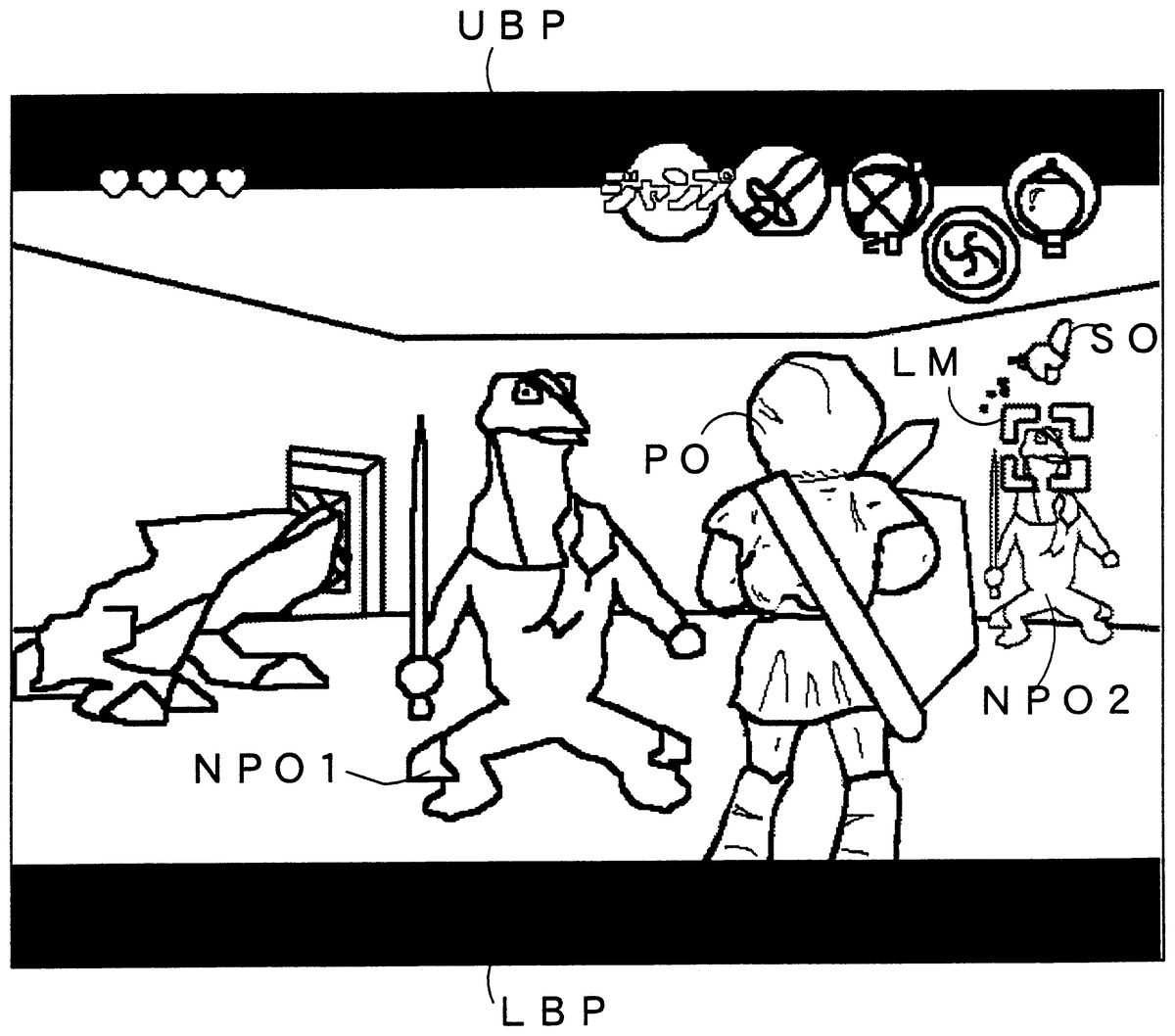
At a step S 308 the display area is decreased in order to recognize the player that the player object is set giving attention to the non-player object, i.e., that an attention process has been done. Specifically, non-display areas (blanking areas) UBP and LBP are provided at top and bottom of the display screen, as shown in FIG. 12 and FIG. 13 . Accordingly, when such area-reduction display is effected, the player can visually recognize that an attention process has been made through the Z button 47 Z. In order to provide such blanking portions UBP and LBP, polygons may be inserted between each object and an icon (as displayed at above locations in FIG. 12 and FIG. 13 ) and affixed with black textures. Otherwise, the image signals may be gated at that portions. It is determined at a next step S 309 whether there exists the selected attention object or not. If YES is determined at this step S 309 , the aforesaid NPO selecting flag F 1 ( FIG. 6 ) is set to 1 .
Incidentally, when a plurality of non-player objects are detected within the field of vision of the player object at the step S 304 , calculations are made at a step S 310 for a straight line distance between each non-player object and the player object to thereby determine a higher priority order of the non-player objects having a shorter straight line distance. At a step S 311 the non-player object given a first priority is selected as an attention non-player object, and the process advances to a forward step S 306 . That is, where there is a plurality of non-player objects within the field of vision of the player object, the non-player object positioned closest to the player object is selected as an attention non-player object.
Further, when the Z button 47 Z is pressed on, if the NPO selecting flag F 1 is set at 1 , that is, one or two or more attention non-player objects have already been selected, the determination at the step S 302 will be YES , and the process advances to the step S 312 . It is determined at this step S 312 whether or not selections have been made for all the non-player objects existing on the display screen. That is, at this step S 312 it is determined whether the attention process has been completed for all the non-player objects including not only the non-player objects being displayed on the display screen but also the non-player objects not being displayed on the display screen.
If NO is determined at the step S 312 , determinations are made on the priority orders according to the straight line distance between each non-player object and the player object, similarly to the aforementioned step S 310 . At a next step S 314 the non-player object given a second priority order is selected as an attention non-player object, and the process advances to a step S 306 .
Because steps S 313 and S 314 are concerned with all the non-player objects except for the non-player objects existing within the field of vision of the player object and already selected as the attention non-player objects, the selections of attention non-player objects at a second time and later are not concerned with whether to exist within the field of vision of the player object. Accordingly, where for example a plurality of non-player objects exist within the field of vision of the player object and one or more non-player objects are present outside the field of vision of the player object, upon a first operation of the Z button a non-player object positioned closest in the field of vision is selected as an attention non-player object. Upon operations of the Z button 47 Z at a second time and later, attention determinations are for the non-player objects present within the field of vision but left unselected as well as the non-player objects existing outside the field of vision. Among these non-player objects, a closest non-player object is given a second priority order.
If NO is determined at a step S 309 , a forward predetermined point located infinitely distant from the player object is considered as a non-player object at a step S 315 , and this point is selected. Accordingly, when the Z button 47 Z is held on, the player object is kept locked at that point.
As another embodiment, where the Z button 47 Z is kept on over a predetermined time period (e.g., time period of several tens of frames in television scan), it is possible to keep the player object locked at that point even if the Z button 47 Z is returned off. In such a case, the lock may be released when the Z button 47 Z is again pressed on.
Now referring to FIG. 10 , at a first step S 401 in the player object process step S 4 (FIG. 8 ), the CPU 11 makes reference to the lock flag F 2 of the RAM 14 to thereby determine whether the attention non-player object is locked or not. If YES is determined at this step S 401 , that is, if the attention non-player object is in a locked state, the CPU 11 at a next step S 402 determines whether there is an instruction of an UP direction in the analog joystick 45 or the cross switch 46 . That is, whether there is an instruction to move the player object in the UP direction or not is determined. If YES , the CPU 11 at a step S 403 moves the player object in a direction toward the selected attention non-player object. Accordingly, the player object is moved to decrease the distance to the attention non-player object while directly facing the attention non-player object (enemy object).
Where DOWN is selected by the analog joystick 45 or the cross key 46 , the player object is moved by steps S 404 and S 405 in a direction away from the selected attention non-player object. That is, when DOWN is instructed, the player object is moved in a direction away from the attention non-player object while facing the attention non-player object.
When a direction of RIGHT is instructed by the analog joystick 45 or the cross key 46 , the CPU 11 at steps S 406 and S 407 moves the player object to rightward while keeping constant the distance between the player object and the attention non-player object In this case, the player object is moved on a circle having as center the attention non-player object, as shown in FIG. 15 . Incidentally, if the player object is paying attention to the aforesaid infinitely distant forward point , when RIGHT is instructed by the analog joystick 45 or the cross key 46 , the player object is moved rightward while maintaining equal the distance to that point. That is, in this case, the player object performs parallel movement in the rightward direction while being directed front on the display screen.
When LEFT is instructed by the analog joystick 45 or the cross key 46 , the player object is moved leftward on a circle having as a center the attention non-player object at steps S 408 and S 409 , as shown in FIG. 14 . That is, the player object is moved leftward while maintaining constant the distance to the attention non-player object. Incidentally, where the player object is giving attention to the infinitely distant forward point , if LEFT is instructed, the player object is moved leftward while keeping equal the distance to that point. That is, in this case, the player object performs a leftward parallel movement with directed frontward on display screen.
The display position of the player object, etc. are registered in the display list area 201 (FIG. 6 ).
Incidentally, where in FIG. 10 the non-player object is not locked, the player object is moved, as shown by the steps S 411 -S 418 , in a direction instructed by the analog joystick 45 or the cross key 46 .
Referring to FIG. 11 , the camera process step S 5 ( FIG. 8 ) will be explained. At a first step S 501 the CPU 11 determines whether the non-player object is locked or not, that is, whether the lock flag F 2 is in setting or not. If YES is determined at this step S 501 , the CPU 11 at a step S 502 moves a hypothetical camera (not shown) to a position at which it is possible to photograph the state that the non-player object and the player object are directly facing to each other. Specifically, the hypothetical camera is moved to a position behind the player object and close to a line (not on the line) connecting between the respective centers of the attention non-player object and the player object. The hypothetical camera is set with its line of vision directed to photograph the attention non-player object. Accordingly, if the Z button 47 Z is switched on, the hypothetical camera is shifted in position and photographing direction so as to photograph from the behind of the player object PO the state that the player object PO faces the non-player object NPO 1 or NPO 2 , as shown in FIG. 12 or FIG. 13 . Accordingly, if the analog joystick 45 or the cross key 46 is operated in this state, the player object as shown in FIG. 14 can be moved while keeping the state that the player object directly faces the attention non-player object, according to the flowchart of FIG. 10 .
At a first step S 701 of the selection object process step S 7 ( FIG. 8 ) shown in FIG. 15 , the CPU 11 determines whether the lock flag F 2 is at 1 or not. When the lock flag F 2 is 1 , the CPU 11 moves a selection object SO ( FIG. 12 or FIG. 13 ) to the above of the attention non-player object, i.e., NPO 1 in FIG. 12 or NPO 2 in FIG. 13 . That is, at this step S 702 the selection object SO is moved to the above of the attention non-player object based depending upon the program data in the selection object program area 22 shown in FIG. 5 and the selection object image data area 203 e ( FIG. 7 ) of the image data area 203 . At a next step S 703 the attention non-player object being selected at that time is detected of its kind. It is determined at a step S 704 whether the attention non-player object is an enemy object or not. That is, although the non-player objects selectable as an attention non-player object include a stationary object besides an enemy object as stated before, it is herein determined whether or not the attention non-player object is an enemy object or a non-player object other than that. If it is an enemy object, the CPU 11 at a step S 705 sets a color for the selection object SO in red through the RDP 123 (FIG. 2 ). If it is a non-player object other than an enemy object, the selection object SO is set in yellow at a step S 706 . After executing the step S 705 or S 706 , the CPU registers the selection object SO to the display list area 201 .
It is noted that, when the attention non-player object is released from its locked state at a step S 708 , the selection object is displayed at a step S 709 at above the player object.
Although the present invention has been described and illustrated in detail, it is clearly understood that the same is by way of illustration and example only and is not to be taken by way of limitation, the spirit and scope of the present invention being limited only by the terms of the appended claims.
Claims
- A video game apparatus coupled to a display, comprising: an image data generator for generating first image data to display a player object;an image processor for supplying an image signal to said display according to said image data in order to display, in a virtual three-dimensional space on said display, the player object photographed through a hypothetical camera from a third person perspective;a controller including a first operating member to instruct a moving direction of the player object and a second operating member that is operable to fix the photographing direction of the player object during game play to a current direction in which the player object is oriented regardless of changes in orientation of the player object after the photographing direction is fixed, wherein the fixed photographing direction is used during real-time game play display the player object from the third person perspective.
- A video game apparatus according to claim 1 , wherein said first operating member includes a direction indicator by which at least four directions, including UP , DOWN , RIGHT and LEFT can be indicated.
Disclaimer: Data collected from the USPTO and may be malformed, incomplete, and/or otherwise inaccurate.