U.S. Pat. No. 6,540,607
VIDEO GAME POSITION AND ORIENTATION DETECTION SYSTEM
Issue DateApril 26, 2001
Illustrative Figure
Abstract
No abstract is available for this record.
Description
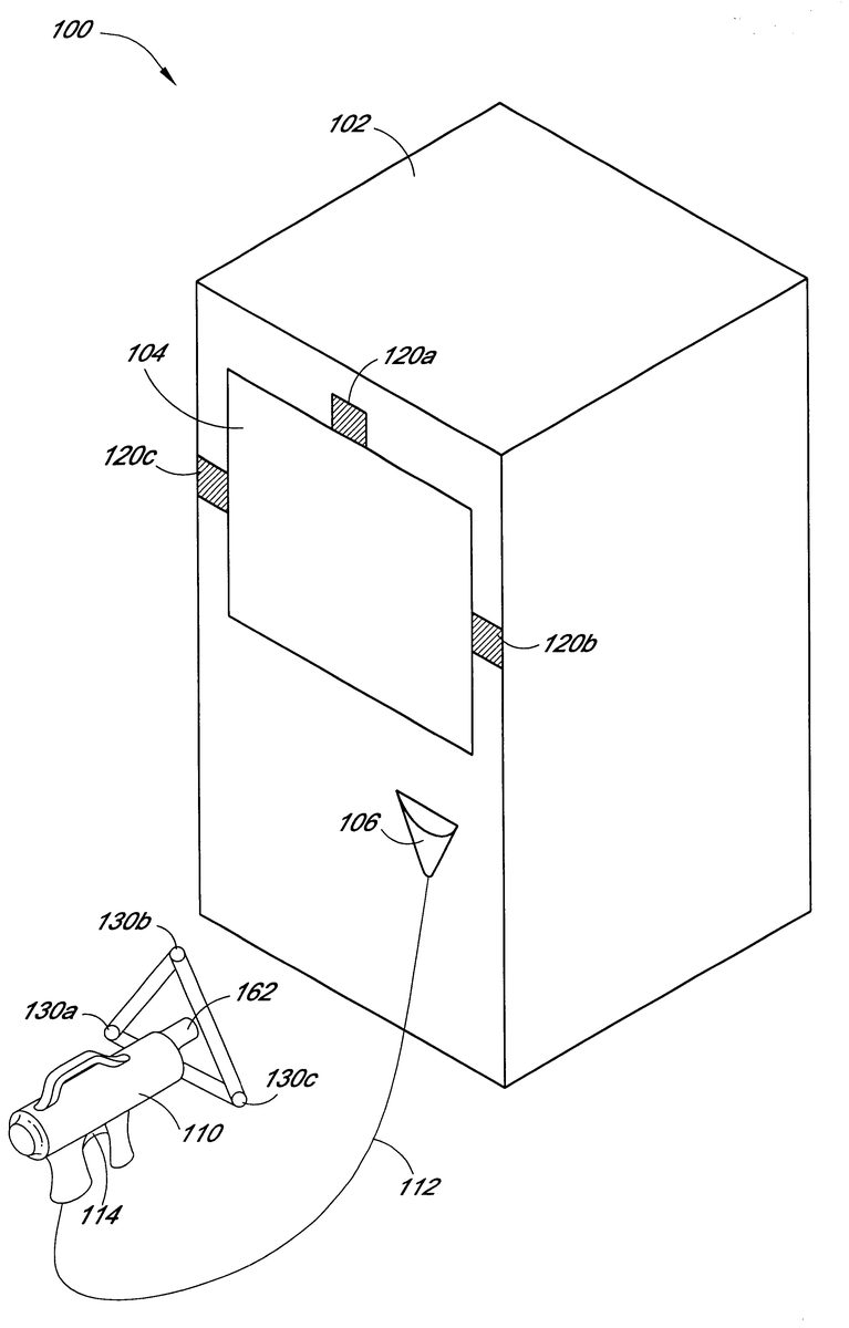
DETAILED DESCRIPTION OF THE PREFERRED EMBODIMENT The following presents a detailed description of certain specific embodiments of the present invention. However, the invention can be embodied in a multitude of different ways as defined and covered by the claims. The invention is best understood by reference to the figures wherein like parts are designated with like numerals throughout. FIG. 1 illustrates a perspective view of a video game machine 100 that includes an embodiment of a position sensor system of the invention. Although the embodiment of the position sensor system described in the following figures and description is presented as a shooting video game, one skilled in the art will recognize that the position sensor system can be used in any application where the position and orientation of an article visible to a control unit is desired. The shooting game machine 100 comprises a housing 102 within which a video display monitor 104 is located facing toward a player (not shown). The video display monitor 104 may be a raster scan or digital display monitor. The housing 102 includes a holder 106 in which a targeting device such as a model gun 110 is received. The model gun 110 is connected to an internal circuit in the housing 102 through a cable 112 . Alternatively, the model gun 110 can be cordless. When the player stands in front of the display with the gun 110 , a game scene is displayed on the video display monitor 104 . The player can aim the gun 110 at targets successively displayed on the video display monitor 104 and pull a trigger 114 on the gun 110 to simulate shooting the targets. The appearance of the shooting game machine of FIG. 1 is basically similar to that of the conventional shooting game machines ...
DETAILED DESCRIPTION OF THE PREFERRED EMBODIMENT
The following presents a detailed description of certain specific embodiments of the present invention. However, the invention can be embodied in a multitude of different ways as defined and covered by the claims. The invention is best understood by reference to the figures wherein like parts are designated with like numerals throughout.
FIG. 1 illustrates a perspective view of a video game machine 100 that includes an embodiment of a position sensor system of the invention. Although the embodiment of the position sensor system described in the following figures and description is presented as a shooting video game, one skilled in the art will recognize that the position sensor system can be used in any application where the position and orientation of an article visible to a control unit is desired.
The shooting game machine 100 comprises a housing 102 within which a video display monitor 104 is located facing toward a player (not shown). The video display monitor 104 may be a raster scan or digital display monitor. The housing 102 includes a holder 106 in which a targeting device such as a model gun 110 is received. The model gun 110 is connected to an internal circuit in the housing 102 through a cable 112 . Alternatively, the model gun 110 can be cordless.
When the player stands in front of the display with the gun 110 , a game scene is displayed on the video display monitor 104 . The player can aim the gun 110 at targets successively displayed on the video display monitor 104 and pull a trigger 114 on the gun 110 to simulate shooting the targets. The appearance of the shooting game machine of FIG. 1 is basically similar to that of the conventional shooting game machines except that the housing 102 has three infrared photo receivers 120 A-C positioned at spaced locations on the housing 102 and adjacent the edge of the monitor 104 . The gun 110 has three infrared LED transmitters 130 A-C positioned on the gun 110 as will be explained below.
In one embodiment, the housing 102 can have three infrared photo receivers 120 A-C positioned about the periphery of the monitor 104 . The receivers 120 A-C can be positioned in a right triangle formation about the monitor 104 so that the base line between receivers 120 A and 120 C forms one leg of the right triangle and the base line between receivers 120 A and 120 B forms the second leg of the right triangle. In one embodiment, the receivers are positioned in the housing 102 so that the base line between receivers 120 A and 120 C and the base line between receivers 120 A and 120 B are 32 inches in length. This distance becomes a calibration distance as discussed below. Alternatively, other receiver orientations and distances between the receivers may be used.
An embodiment of the gun 110 is illustrated as including three infrared led transmitters 130 A-C positioned on the gun 110 . Although the depicted embodiment describes the transmitters 103 A-C mounted on the gun and the receivers 120 A-C mounted on the housing 102 , it is also understood that embodiments of the invention can have the transmitters mounted on the housing and the receivers mounted on the gun. The transmitters 130 A-C can be positioned on the gun 110 so that they are located at the corners of an equilateral triangle. In one embodiment, the transmitters 130 A-C are positioned so that each side of the equilateral triangle formed by the three transmitters 130 A-C is six inches in length. Alternatively, distances greater than or less than six inches and orientations other than an equilateral triangle can be used. The transmitters 130 A-C can be commercially available transmitters such as a model PDI-E804 from Photonic Detectors, Inc., which have the desirable optical qualities of broadcasting light over a wide and even pattern.
The transmitters 130 A-C are positioned on the gun 110 and the gun 110 is located for use in such a manner that there is no obstruction between the transmitters 130 A-C and the receivers 120 A-C. The transmitters 130 A-C can be positioned on the gun 110 so that each is recessed in a respective beveled hole in the body of the gun (not shown). The beveled holes can be of sufficient depth so as to prevent contact by the player with the transmitters 130 A-C. However, the transmitters 130 A-C should be close enough to the surface of the beveled holes on the gun 110 so that the light from the transmitters 130 A-C does not reflect off the interior surfaces of the holes.
The transmitters 130 A-C emit a modulated, infrared light signal over a tightly controlled bandwidth. In one embodiment, the transmitters 130 A-C emit a square wave with a 50% duty cycle at about 31k Hz. As explained below, the transmitters 130 A-C receive a control signal dictating when to transmit. In one embodiment, each transmitter 130 A-C is time sequenced to transmit for th of the total transmit time. In one embodiment, the shooting game machine 100 can include two guns 110 A and 110 B, each gun 110 A, 110 B having three transmitters 130 A-C. Therefore, in this embodiment, there are six transmitters 130 , making it desirable that each transmitter 130 be active for th of the total transmit time. This allows the transmitters 130 A-C on gun 110 A and the transmitters 130 A-C on gun 110 B to be sequenced so that the three receivers 120 A-C will receive a signal from only a single transmitter 130 at any given time. Alternatively, one skilled in the art will recognize that code division multiplexing can be used enabling two transmitters to emit signals at the same time, with their modulation in quadrature.
FIG. 2 is a block diagram showing receiver 120 A mounted on an IReye board 122 A. Receivers 120 B-C (not shown) are similarly mounted on identical IReye boards 122 B-C, respectively. The receivers 120 A-C are photo diode receivers such as model LTR-516AD available from LITE-ON, Inc. The receivers 120 A-C are receptive to an AC signal at a wide range of frequencies. The receivers 120 A-C convert the amount of light received at all amplitudes within the bandwidth of the circuit into an analog signal proportional to the amount of light received. Each of the IReye boards 122 A-C amplifies the signal using a low noise op-amp 126 and then a differential driver op-amp 128 and then outputs the signal. The IReye boards 122 A-C gather light energy, for example, square-wave modulated light. Alternatively, other forms of modulation, such as sine-wave modulation or triangle-wave modulation can be used. It is preferable that the IReye boards 122 A-C do not gather DC light sources such as sunlight or flash light.
FIG. 3 is a block diagram illustrating an Eyecon board 140 located in the housing 102 ( FIG. 1 ) and shows that the analog signal from each IReye board 122 A-C is received by a differential input amplifier 142 on the Eyecon board 140 . The signals are then sent to an inverter buffer 144 . The signals are then sent to a multiplexer (MUX) 146 that switches at the transmission frequency. This method of signal reconstruction is known as a synchronous detector (code-division-multiplexing) and is known in the art. The resulting polarized analog signal is sent from the MUX 146 to a low pass filter buffer 148 . The signal is then sent to an analog-to-digital converter (A/D) 150 . In this system, the signal, plus its inversion, when read synchronously will add up to the original signal, minus interference noise. A serial control connects the A/D converter 150 to a control EPLD 152 which provides a convenient parallel connection to a game-control processor (not shown), as well as providing timing signals to the gun 110 , receivers, 120 A-C and other auxiliary input/output devices such as flashing lights (not shown).
The control EPLD 152 is also electrically connected to the gun 110 through the cable 112 . The control EPLD 152 controls the timing cycle of the transmitters 130 A-C on the gun 110 so that only one transmitter is active at a time. A processor 160 located in the housing 102 is connected to the control EPLD 152 . The ELPD synchronizes the signals with the corresponding transmitter and sends the data to the processor 160 . The processor 160 converts the signals into position data for each of the transmitters 130 A-C.
As discussed above, in one embodiment the receivers 120 A-C are positioned around the display monitor 104 to define a right triangle configuration. Referring back to FIG. 1 , in one embodiment, the base line distance between the receivers 120 A and 120 B and between receivers 120 A and 120 C is 32 inches. This distance of 32 inches is defined as D or one light scale unit (LSU). Of course, it is conceived that other distances can be selected for this reference unit.
The three transmitters 130 A-C are calibrated by noting the light amplitude for each transmitter 130 A-C while placed directly over each receiver 120 A-C at a distance of one LSU. Noting that the intensity of light varies as the inverse square of the distance the light travels (assuming a spreading light source), the distance can be calculated by dividing a proportionality constant by the square root of the light reading. The distance then defines a sphere centered on the respective receiver with the radius of the sphere equal to the distance of the transmitter 130 from the receiver 120 .
The distances calculated from the light readings then can be used to calculate position of the transmitters 130 A-C as now discussed. The distance a first transmitter, for example 130 A, is from receiver 120 A defines a first sphere centered on the receiver. Likewise, the distance from receiver 120 B defines a second sphere and the distance from 120 C defines a third sphere. The intersection of the first two spheres defines a circle. Then, the intersection of the third sphere and the above-defined circle defines two points. One of the points will be located behind the housing 102 and can be eliminated.
The distances to the other two transmitters 130 B and 130 C are similarly determined. This allows the calculation of the positions of the points of the three transmitters 130 A-C in three dimensional space, thereby defining a plane on which the transmitters 130 A-C are located.
Referring back to FIG. 1 , the geometry of the transmitters 130 A-C positioned on the gun 110 is illustrated. The three-space coordinates of the transmitters determined above now define a triangle in space. A weighted average of those coordinates can be used as the (x,y,z) of the tip of the gun-muzzle 162 . In one embodiment where the transmitters 130 A-C are positioned in an equilateral triangle as described above, the weights of the coordinates are the same, simplifying the calculation.
The midpoint of the plane and the perpendicular vector pointing in the direction of the three receivers 120 A-C can now be calculated. The cross-product of two of the vectors defined between the transmitters 130 A-C will give the normal vector to the plane defined by the three transmitters. For example, the cross-product of the vector from transmitter 130 A to transmitter 130 B and the vector from transmitter 130 B to transmitter 130 C defines a vector normal to the plane containing the three transmitters. Using the position and orientation of the triangle of transmitters, the position and orientation of the gun 110 is calculated. For example, the muzzle of the gun 110 would be within the triangle, and the barrel of the gun is parallel to the normal vector calculated above.
The receivers 120 A-C are located around the monitor 104 in a right triangle configuration to promote the least obstructed pathway between transmitters 130 A-C and receivers 120 A-C (taking into account players of various sizes and/or pedestals that may be added to the configuration of the housing 102 ). Since the output from this system will be mapped onto a rectangular monitor 104 with coordinates that align with horizontal and vertical, the data must be rotated 45 degrees counter clockwise from the XYZ coordinate system of transmitter 120 A to that of the monitor 104 . This is easily accomplished by rotating the data around a known point, such as the center of the monitor 104 . This point, though virtual, is well defined and scales with both the size of the monitor 104 and the length of the legs of the right triangle formed by the receivers 120 A-C.
A method 400 of operating of the position sensor system will now be described with reference to FIG. 4 . In step 402 , a signal is generated by the Eyecon board 140 directing the first transmitter 130 to emit a light signal. The system then moves to a step 404 , wherein the light signal is received by the receivers 120 A-C. The system then moves to a step 406 , wherein the light received from the transmitter 130 is converted into an analog signal, which is amplified and sent to the Eyecon board 140 . Next, in step 408 , the Eyecon board 140 uses code-division multiplexing to remove noise and then converts the analog signals into digital signals as explained above. In one embodiment, the transmission time period for any one transmitter is enough to allow more than one conversion of the analog signal by the A/D converter 150 on the Eyecon board 140 . For example, the time period can be such that six signals are generated for each transmitter. Multiplying these six signals by three receivers 120 A-C, it can be seen that a total of eighteen sets of raw data are passed to the processor 160 during this step.
The system then moves to a step 410 , wherein the processor 160 takes the six sets of data from each of the three receivers 120 A-C, sums and averages the data, and produces three averaged values, (one for each receiver from the one transmitter of that time period), which are stored by the processor 160 . The sequence then proceeds to the next transmitter 130 . In an embodiment with one gun 110 , this sequence continues until each of the three transmitters 130 A-C have been activated for their period of time, producing nine averaged values. In the embodiment having two guns 110 A and 110 B, this sequence would proceed through all six transmitters 130 to produce a total of eighteen averaged values. The process then starts over again with the first transmitter 130 . In one preferred embodiment, one cycle through all six transmitters 130 can be completed in less than {fraction (1/60)} of a second.
In step 412 , the processor 160 uses the eighteen sets of averaged data to determine the XYZ coordinates of the six transmitters 130 . In step 414 , the plane of the three transmitters 130 A-C on each gun 110 A and 110 B is calculated and the vector normal to the plane through the midpoint is calculated. These values are then sent to the video game software to be used by the processor 160 in the generation of the three-dimensional scenes displayed on the display monitor 104 .
The three-dimensional coordinates and the orientation of the gun 110 as calculated are input to the processor 160 and used to generate three-dimensional scenes displayed on the display monitor 104 . The position and vector can be used to project a virtual vector into the scene of the game depicting the targeted position of the gun 110 or to display the trajectory of gunfire or laser shots from the gun 110 into the displayed scene.
Specific blocks, sections, devices, functions and modules have been set forth. However, a skilled technologist will realize that there are many ways to partition the system of the present invention, and that there are many parts, components, modules or functions that may be substituted for those listed above. Although the above detailed description has shown, described and pointed out fundamental novel features of the invention as applied to various embodiments, it will be understood that various omissions and substitutions and changes in the form and details of the device illustrated may be made by those skilled in the art, without departing from the spirit of the invention.
Claims
- A targeting game machine comprising: a display monitor for displaying a target;at least one targeting device;at least three transmitters for emitting infrared light signals, wherein at least three transmitters are mounted on the at least one targeting device;at least three photodiode receivers capable of detecting the light signals from said transmitters, wherein the receivers are mounted about the display monitor;a receiver circuit electrically connected to said receivers, wherein the receiver circuit generates signals in relation to the intensity of the infrared light signals detected by the receivers, the generated signals representing the distance of the transmitters from the receivers;and a processor for processing the signals to determine the three-dimensional coordinate position and orientation of the targeting device with respect to the display monitor.
- The targeting game machine of claim 1 wherein the transmitters are time sequenced so that only one of the plurality of transmitters emits a signal at a time.
- The targeting game machine of claim 1 , comprising two targeting devices.
- The targeting game machine of claim 3 wherein three transmitters are connected to each of the targeting devices.
- The targeting game machine of claim 1 wherein the transmitters are positioned on the targeting device at the corners of a triangle formation.
- The targeting game machine of claim 1 wherein the transmitters emit a square-wave modulated light signal.
- The targeting game machine of claim 1 wherein the receivers are positioned about the monitor at the comers of a right triangle formation.
- The targeting game machine of claim 1 , wherein the processor determines a plane defined by the position of the transmitters mounted on the targeting device and the perpendicular vector pointing in the direction of the receivers.
- A method of displaying the targeted location of a targeting device relative to a display monitor for use in a targeting game machine, said targeting device having a plurality of transmitters connected to said targeting device, and said display monitor having a plurality of receivers fixedly mounted to said monitor, said method comprising: emitting light signals from the transmitters connected to the targeting device;detecting light signals emitted from the transmitters at the receivers;calculating three-dimensional positions of the transmitters connected to the targeting device;calculating a vector of the targeting device from the positions of the transmitters;and displaying a line pointer that depicts the vector of the targeting device with respect to the display monitor, wherein the line pointer starts from a front surface of the monitor and projects into a three-dimensional scene displayed on said monitor.
- A method of detecting the position and orientation of a targeting device relative to a display monitor, said targeting device having a plurality of transmitters or receivers connected to said targeting device, and said display monitor having a plurality of receivers or transmitters fixedly mounted thereto, said method comprising: emitting light signals from the transmitters;detecting the light signals emitted from the transmitters at the receivers;calculating the distance between the transmitters and the receivers using the light signals detected by the receivers;determining the three-dimensional position and orientation of the targeting device with respect to the display monitor using the distance between the transmitters and receivers;and wherein light signals are detected from three transmitters connected to the targeting device.
Disclaimer: Data collected from the USPTO and may be malformed, incomplete, and/or otherwise inaccurate.