U.S. Pat. No. 6,290,604
Video game apparatus and memory medium used therefor
Issue DateJanuary 22, 2001
Illustrative Figure
Abstract
No abstract is available for this record.
Description
DETAILED DESCRIPTION OF ONE PREFERRED EMBODIMENT Referring to FIG. 1, a video game system in this embodiment includes a video game machine 10, a ROM cartridge 20 as one example of a memory medium, a display unit 30 connected to the video game machine 10, and a controller 40. The controller 40 is dismountably mounted with a cartridge 50. The controller 40 is structured by a plurality of switches or buttons provided on the housing 41 in a form graspable by both or one hand. Specifically, the controller 40 includes handles 41L, 41C, 41R downwardly extending respectively from a left end, a right end and a center of the housing 41, providing an operation area on a top surface of the housing 41. In the operation area, there are provided an analog-inputtable joystick (hereinafter referred to as "analog joystick") 45 at a central lower portion thereof, a cross-shaped digital direction switch (hereinafter called "cross switch") 46 on the left side, and a plurality of button switches 47A, 47B, 47D, 47E and 47F on the right side. The analog joystick 45 is used to input moving directions and/or moving speeds or moving amounts of the player object as determined by an amount and direction of joystick inclination. The cross switch 46 is used to designate a moving direction of the player object, in place of the joystick 45. The button switches 47A and 47B are used to designate a motion of the player object. Button switches 47C-47D are used to switch over a sight point for a three-dimension image camera or to adjust the speed or the like of the player object. A start switch 47S is provided almost at a center of the operation area. This start switch 47S is operated when starting a game. A switch 47Z is provided ...
DETAILED DESCRIPTION OF ONE PREFERRED EMBODIMENT
Referring to FIG. 1, a video game system in this embodiment includes a
video game machine 10, a ROM cartridge 20 as one example of a memory
medium, a display unit 30 connected to the video game machine 10, and a
controller 40. The controller 40 is dismountably mounted with a cartridge
50.
The controller 40 is structured by a plurality of switches or buttons
provided on the housing 41 in a form graspable by both or one hand.
Specifically, the controller 40 includes handles 41L, 41C, 41R downwardly
extending respectively from a left end, a right end and a center of the
housing 41, providing an operation area on a top surface of the housing
41. In the operation area, there are provided an analog-inputtable
joystick (hereinafter referred to as "analog joystick") 45 at a central
lower portion thereof, a cross-shaped digital direction switch
(hereinafter called "cross switch") 46 on the left side, and a plurality
of button switches 47A, 47B, 47D, 47E and 47F on the right side.
The analog joystick 45 is used to input moving directions and/or moving
speeds or moving amounts of the player object as determined by an amount
and direction of joystick inclination. The cross switch 46 is used to
designate a moving direction of the player object, in place of the
joystick 45. The button switches 47A and 47B are used to designate a
motion of the player object. Button switches 47C-47D are used to switch
over a sight point for a three-dimension image camera or to adjust the
speed or the like of the player object.
A start switch 47S is provided almost at a center of the operation area.
This start switch 47S is operated when starting a game. A switch 47Z is
provided at a backside of the central handle 41C. This switch 47Z is
utilized, for example, as a trigger switch in a shoot game. This switch
(may be hereinafter called "Z button") 47Z is operated when the player
object is to be caused to pay attention to a non-player object. That is,
this switch 47Z functions as a second operating means. Switches 47L and
47R are provided at upper left and right of a lateral surface of the
housing 41.
Incidentally, the above-stated button switches 47C-47F can also be used to
control the moving speed (e.g. acceleration or deceleration) of the player
object in a shoot or action game, besides for the purpose of switching the
camera visual point. However, these switches 47A-47F, 47S, 47Z, 47L and
47R can be arbitrarily defined in their function depending upon a game
program.
FIG. 2 is a block diagram of the video game system of the FIG. 1
embodiment. The video game machine 10 incorporates therein a central
processing unit (hereinafter referred to as "CPU") 11 and a coprocessor
(reality coprocessor: hereinafter referred to as "RCP") 12. The RCP 12
includes a bus control circuit 121 for controlling buses, a signal
processor (reality signal processor; hereinafter referred to as "RSP") 122
for performing polygon coordinate transformation, shading treatment and so
on, and a rendering processor (reality display processor; hereinafter
referred to as "RDP") 46 for rasterizing polygon data into an image to be
displayed and converting the same into a data form (dot data) memorable on
a frame memory.
The RCP 12 is connected with a cartridge connector 13 for unloadably
loading a ROM cartridge 20 having an external ROM 21 incorporated therein,
a disc-drive connector 197 for detachably mounting a disc drive 29, and a
RAM 14. Also, the RCP 12 is connected with DAC (Digital/Analog Converters)
15 and 16 for respectively outputting a sound signal and video signal to
be processed by the CPU 11. Further, the RCP 12 is connected with a
controller control circuit 17 to serially transfer operating data on one
or a plurality of controllers 40 and/or data of the cartridge 50.
The bus control circuit 121 included in the RCP 12 performs parallel/serial
conversion on a command supplied in a parallel signal from the CPU via a
bus, to thereby supply a serial signal to the controller control circuit
18. Also, the bus control circuit 121 converts a serial signal inputted
from the controller control circuit 17 into a parallel signal, giving an
output to the CPU 11 via the bus. The data representative of an operating
state (operating signal or operating data) read out of the controller
40A-40D is processed by the CPU 11, and temporarily stored within a RAM
14, and so on. In other words, the RAM 15 includes a storage site for
temporarily memorizing the data to be processed by the CPU 11, so that it
is utilized for smoothly reading and writing data through the bus control
circuit 121.
The sound DAC 15 is connected with a connector 195 provided at a rear face
of the video game machine 10. The image DAC 16 is connected with a
connector 196 provided at the rear face of the video game machine 10. The
connector 195 is connected with a speaker 31 of a display 30, while the
connector 196 is connected with a display 30 such as a TV receiver, CRT or
LCD.
The controller control circuit 17 is connected with a controller connector
provided at the front face of the video game machine 10. The connector 18
is disconnectably connected by a controller 40 through a connecting jack.
The connection of the controller 40 to the connector 18 places the
controller in electrical connection to the video game machine 10, thereby
enabling transmission/reception or transfer of data therebetween.
The controller control circuit 17 is used to transmit and receive data in
serial between the RCP 12 and the connector 18. The controller control
circuit 17 includes, as shown in FIG. 3, a data transfer control circuit
171, a transmitting circuit 172, a receiving circuit 173 and a RAM 174 for
temporarily memorizing transmission and reception data. The data transfer
control circuit 171 includes a parallel/serial converting circuit and a
serial/parallel converting circuit in order to convert a data format
during data transfer, and further performs write/read control on the RAM
174. The serial/parallel converting circuit converts the serial data
supplied from the RCP 12 into parallel data, supplying it to the RAM 174
or the transmitting circuit 172. The parallel/serial converting circuit
converts the parallel data supplied from the RAM 174 or the receiving
circuit 173 into serial data, to supply it to the RCP 12. The transmitting
circuit 172 converts the command for reading signals from the controller
40 and the writing data (parallel data) to the cartridge 50, into serial
data to be delivered to channels CH1-CH4 corresponding to the respective
controllers 40. The receiving circuit 173 receives, in serial data,
operational state data of the controllers inputted through corresponding
channels CH1-CH4 and data read from the cartridge 50, to convert them into
parallel data to be delivered to the data transfer control circuit 171.
The data transfer control circuit 171 writes into the RAM 174 data
transferred from the RCP 12, data of the controller received by the
receiving circuit 183, or data read out of the RAM cartridge 50, and reads
data out of the RAM 174 based on a command from the RCP 12 so as to
transfer it to the RCP 12.
The RAM 174, though not shown, includes memory sites for the respective
channels CH1-CH4. Each of the memory sites is stored with a command for
the channel, transmitting data and/or reception data.
FIG. 4 is a detailed circuit diagram of the controller 40 and the cartridge
50. The housing of the controller 40 incorporates an operating signal
processing circuit 44, etc. in order to detect an operating state of the
joystick 45, switches 46, 47, etc. and transfer the detected data to the
controller control circuit 17. The operating signal processing circuit 44
includes a receiving circuit 441, a control circuit 442, a switch signal
detecting circuit 443, a counter circuit 444, a joyport control circuit
446, a reset circuit 447 and a NOR gate 448. The receiving circuit 441
converts a serial signal, such as a control signal transmitted from the
controller control circuit 17 or writing data to the cartridge 50, into a
parallel signal to supply it to the control circuit 442. The control
circuit 442 generates a reset signal to reset (0), through the NOR gate
448, count values of an X-axis counter 444X and a Y-axis counter 444Y
within the counter 444, when the control signal transmitted from the
controller control circuit 17 is a signal for resetting X, Y coordinates
of the joystick 45.
The joystick 45 includes X-axis and Y-axis photo-interrupters in order to
decompose a lever inclination into X-axis and Y-axis components,
generating pulses in number proportional to the inclination. The pulse
signals are respectively supplied to the counter 444X and the counter
444Y. The counter 444X counts a number of pulses generated in response to
an inclination amount when the joystick 45 is inclined in the X-axis
direction. The counter 444Y counts a number of pulses generated responsive
to an inclination amount when the joystick 45 is inclined in the Y-axis
direction. Accordingly, the resultant X-axis and Y-axis vector determined
by the count values of the counters 444X and 444Y serves to determine a
moving direction and a coordinate position of the player object or hero
character or a cursor. Incidentally, the counter 444X and the 444Y are
reset, when a reset signal is supplied from the reset signal generating
circuit 447 upon turning on the power or a reset signal is supplied from
the switch signal detecting circuit 443 by simultaneous depression of
predetermined two switches.
The switch signal detecting circuit 443 responds to a switch-state output
command supplied at an interval of a constant period (e.g. a 1/30+L
second interval as a TV frame period) from the control circuit 442, to
read a signal varying depending upon a depression state of the cross
switch 46 and the switches 47A-47Z. The read signal is delivered to the
control circuit 442. The control circuit 442 responds to a read-out
command signal of operational state data from the controller control
circuit 17 to supply in a predetermined data format the operational state
data on the switches 47A-47Z and count values of the counters 444X and
444Y to the transmitting circuit 445. The transmitting circuit 445
converts the parallel signal outputted from the control circuit 442 into a
serial signal, and transfer it to the controller control circuit 17 via a
converting circuit 43 and a signal line 42. The control circuit 442 is
connected with a joystick control circuit 446 via an address bus and a
data bus as well as a port connector 46. The joyport control circuit 446
performs data input/output (or transmission/reception) control according
to a command from the CPU 11 when the cartridge 50 is connected to the
port connector 46.
The cartridge 50 is structured by connecting the RAM 51 to the address bus
and data bus and connecting the RAM 51 with a battery 52. The RAM 51 is a
RAM having a capacity (e.g. 256 k bits), for example, of lower than a half
of a maximum memory capacity accessible through the address bus. The RAM
51 is to store backup data in relation to a game, and saves backup data by
the application of electric power from the battery 52 even if the
cartridge 50 is withdrawn from the port connector 46.
FIG. 5 is a memory map showing a memory space of the external ROM 21
incorporated in the ROM cartridge 20 (FIG. 1). The external ROM 21
includes a plurality of memory areas (hereinafter referred to merely as
"area"), for example, such as a program area 22, a character code area 23,
an image data area 24 and a sound memory area 25, as shown in FIG. 5,
thereby previously storing various program in a fixed manner.
The program area 22 is stored with programs required to process for game
images, and game data and the like in accordance with a game content.
Specifically, the program area 22 includes a plurality of memory areas to
previously store operating programs for the CPU 11 in a fixed manner. A
main program area 22a is stored with a main routine processing program,
for example, for a game shown in FIG. 8 stated later. A controller data
program area 22b is stored with a program for processing operational data
on the controller 40. A write program area 22c is stored with a write
program by which the CPU 11 causes the RCP 12 to perform writing into a
frame memory and Z buffer. For example, the write program area 22c is
stored with a program to write, into an image data area 203 (FIG. 6, FIG.
7) of the RAM 14, chrominance data as image data based on texture data for
a plurality of movable objects or background objects to be displayed in
one background scene. A move program area 22d is stored with a control
program by which the CPU 11 causes the RCP 12 to vary the position of a
moving body in a three-dimension space. A camera control program area 22e
is stored with a camera control program that controls as to in which
direction and/or position the movable objects including player object or
the background objects are to be photographed in the three-dimension
space. A player object program area 22f is stored with a program that
controls, in displaying, an object operated by the player (player object).
A ground object program area 22g is stored with a program to control, in
displaying, a ground object (a ground, water surface, floor, etc.) on or
above which the player object may stand or exist. A shadow object program
area 22h is stored with a program to display a shadow of the player object
on a ground object according to the data of a light object for
illuminating the player object.
The character code area 23 is an area to store a plurality of kinds of
character codes, e.g. a plurality of kinds of character dot data
corresponding to the codes. The character code data memorized in the
character code area 23 is utilized to display an instruction sentence to
the player in the process of a game.
An image data area 24 is stored with image data, such as coordinate data of
a plurality of polygons for each of the background object and/or movable
objects, and texture data, and also a display control program to display
these objects stationary at a predetermined position or in a moving state.
A sound memory area 25 is stored with sound data, such as phrases for
outputting in sound the above message, effect sounds, game musics (BGM),
etc., in a manner appropriate for a scene.
Incidentally, the memory medium or external memory device may use various
kinds of memory mediums, such as CD-ROMs or magnetic discs, in place of or
in addition to the ROM cartridge 20. In such a case, a disc drive 29 (FIG.
2) is provided in order to read or write, if required, various data
(including program data and data for image presentation) for a game from
or onto an optical or magnetical disc memory medium such as a CD-ROM or
magnetic disc. The disc drive 29 reads data out of a magnetic disc or
optical disc magnetically or optically memorizing program data similarly
to the external ROM 21, and transfer the same data to the RAM 14.
FIG. 6 is a memory map illustrative of a memory space of the RAM 14. The
RAM 14 includes a display list area 201. When the player object or the
non-player object is to be displayed, its object No. is registered in the
display list area 201. The RAM 14 includes further a program area 202 and
an image data area 203. The image data area 203 includes a frame memory
area 203a to temporarily memorize 1 frame of image data, and a Z buffer
area 203b to memorize, dot by dot, depth data of the frame memory area.
The image data area 203 further includes, as shown in FIG. 7, a player
object image data area 203c, an animation table area 203d, a ground object
image data area 203e, a basic shadow object image data area 203f and an
other-object image data area 203g. The areas 203c-203g each temporarily
memorizes polygon data or texture data. However, the animation table area
203d is memorized with an animation data table as shown in FIG. 15
hereinafter referred to.
The program data area 202 is to temporarily memorize a program. The program
data given on each area of the ROM 21 (FIG. 5) is temporarily memorized,
as required, in the program data area 202. The CPU 11 and the RCP 12 (FIG.
2) make access to the program area thereby putting the game forward.
Similarly, the image data area 203 is to temporarily memorize, as
required, the image data stored in the ROM 21, which is directly
accessible by the CPU 11 or the RCP 12. That is, the image data area 203
memorizes coordinate data and texture data for a plurality of polygons to
constitute a stationary object and/or movable object stored, for game
image display, in the external ROM 21, to which 1 course or stages of data
is transferred, prior to image processing, from the external ROM 21.
A sound memory area 204 temporarily memorizes sound data of BGM or effect
sound given on the sound memory area 25 of the ROM 21, as shown in FIG. 5.
A controller data memory area 205 temporarily memorizes operation status
data indicative of an operation status read out through the controller 40.
Also, a flag register area 206 sets a flag, or memorizes variables or
constants as required, during execution of a program by the CPU 11. The
registers to be set on this flag register area 206 includes a light number
register (Ln) representative of the number of light sources (natural
light, external light or point light) existing in one virtual
three-dimensional space (scene), a ground object number register (ob1)
representative of the number of ground objects on which shadows are to be
displayed, an other-object number register (ob2) representative of the
number of other objects, a length register (F1, F2) representative of a
leg length of the player object, a length register (Fmax) representative
of a maximum leg length of the player object, a height register (h1, h2)
representative of a foot height of the player object, an angle register
(.theta.) representative of an angle of light illuminated from a point
light and a length register (X1, X2) representative of a length of a
shadow to be displayed.
The basic shadow object image data area 203f shown in FIG. 7 is memorized,
for example, with the polygon data or texture data of a basic shadow
object, shown in FIG. 8. That is, the basic shadow object is in a circular
form represented by two sets of polygons, wherein this embodiment has
texture data that gives three steps of depth (transparency) degrees. The
shadow is highest in depth and hence lowest in transparency at a central
portion thereof. The respective portions has transparency stepwisely
increased with decrease in depth as the center of the shadow is gone
distant. In this embodiment, the basic shadow object is deformed in each
scene so that a shadow object can be created and displayed on a ground for
the player object in an realistic fashion. This satisfies at the same time
the requirements of relieving the burden of calculation and providing
versatility in displaying shadows.
FIG. 9 is a main flowchart for the video game system in this embodiment.
When a power is turned on, the CPU 11 at a first step S1 sets the video
game machine 10 to a predetermined initial state in order to start
operation. For example, the CPU 11 transfers a start program among the
game programs stored in the program area 22 of the external ROM into the
program area 202 of the RAM 14, and sets each parameter to an initial
value and executes the steps of FIG. 9 in the order.
The operation of the main flowchart of FIG. 8 is executed, for example,
every 1 frame (1/60 second) or every two or three frames, wherein steps
S1-S13 are repeatedly executed before the course is cleared. If the game
becomes over without success of course clear, a game-over process is
effected at a step S14 following the step S13. If course clear is
successfully done, the process returns from the step S13 to the step S1.
That is, at a step S1 a game course screen and/or course opting screen is
displayed. However, when the game is started after turning on the power, a
first course screen is displayed. If the first course is cleared, a next
course is set on.
At a step S2 following the step S1, a controller process is performed. This
process includes a detection on any of which the joystick 45, cross switch
46 and switches 47A-47Z on the controller has been operated. The operation
state detection data (controller data) is read in, and the controller
data, thus read is written into the controller data area 205 of the RAM
14.
At a step S3, the positional data of a light for illuminating the player
object, e.g., a point light or external light (natural light), is
processed. For example, the number of light sources to illuminate the
player object is written into the light number register Ln, and further,
the image data of a light object other than the natural light is written
from the image data area 24 (FIG. 5) of the RAM 21 into the image data
area 203 of the RAM 14. If there is a light object, that light object is
registered in the display list area 201 of the RAM 14.
At a step S4 a process for displaying a ground object is carried out. This
step S4 is executed concretely by a subroutine shown in FIG. 10. At a
first step S401 in FIG. 1, the ground object number register obl is set at
"1". At a next step S402 the ground object is registered in the display
list area 201 (FIG. 6). At a step 403 the ground object number register
obl is incremented. Then it is determined at a next step S404 whether all
the ground objects have been registered in the display list area 201. If
"NO" at the step S404, the process returns to the step S402 to repeat the
steps S402 and S403 until the process for the ground object is ended.
At a step S5 a process for displaying a player object is carried out. This
process is concretely executed by a subroutine of FIG. 11. At a first step
S501 in FIG. 11, the player object is moved in position based on an
operating state of the player-operated joystick 45 and cross key 46 or a
program transferred from the memory area 22f (FIG. 6) of the external ROM
21 and the polygon data for the player object transferred from the memory
area 24, i.e. an operating state of the joystick 45 and cross key 46. At a
next step S502 the player object is changed in movement in response to a
button 47 operating state (controller data) on the controller 40. The
polygon data after changing the movement is determined by calculation. At
a step S503 the player object is registered in the display list area 201.
At a step S6 a process for other objects is carried out. This step includes
calculation of a position or shape of an other object based on a program
partly transferred from the memory area 22h and the polygon data of the
other object transferred from the memory area 24 (FIG. 5).
At a step S7 a process for displaying a shadow object is carried out. This
step S7 is executed concretely by a subroutine shown in FIG. 12.
At a first step S701 in FIG. 12, the CPU 11 (FIG. 2) sets "1" in the light
number register Ln of the RAM 14. At next steps S702 and S703 the left and
right feet are detected in position. Where the player object is the one as
shown in FIG. 13, the CPU 11 detects a coordinate (x1, y1, z1) of a left
heel and a coordinate (x2, y2, z2) of a right heel respectively at steps
S702 and S703.
At next steps S704 and S705 the CPU 11 checks on floors (ground objects)
respectively existing under the left and right feet based on the image
data of the ground object image data area 203e in FIG. 7. Specifically,
checks are made on positions, inclination and materials (water, soil,
etc.) of the ground objects.
At steps S706 and S707 the left and right foot shadows are respectively
determined in position. In these steps S706 and S707, the foot shadows are
determined in position respectively by changing, only in (height) "y", the
heel coordinate positions (x1, y1, z1) and (x2, y2, z2) detected at the
afore-said steps S702 and S703.
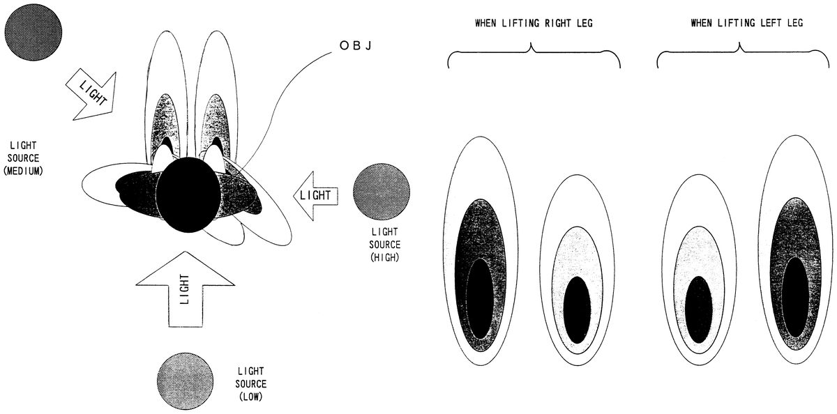
Subsequently, at a step S708 the CPU 11 detects a direction of the light
designated at the afore-said step S701. For example, the coordinate
position of a point light is detected based on the image data stored in
the other-object image data area 203g (FIG. 7) of the RAM 14.
At a step S709 a direction to which the shadow of the player object is to
be extended is determined. The coordinate position of a center of the
player object (FIG. 13) is read out of the player object image data area
203c and then at a step S708 the point light is detected in coordinate
position. Accordingly, the direction in which a shadow is to be extended
is given as an opposite side to a line connecting between the coordinate
positions of that center and the point light. Assuming, with reference to
FIG. 14, that the player object OBJ is being irradiated by light from a
behind thereof, the shadow of the player object will extend in a forward
direction thereof on a line connecting between the player object and the
light. That is, the direction of the shadow is determined such that the
shadow extends in an opposite direction to the light on the line
connecting between the light and the player object.
At a next step S710 the point light having designated at the step S701 is
detected of its height. Because the coordinate position of the point light
has been detected at the step S708, the step S710 is to detect only
"y"(height) data at the coordinate position. The reason of detecting the
point light height is that, as shown in FIG. 14, the length of the player
object shadow varies depending upon the height i.e., "high", "medium" or
"low", of the point light.
At next steps S711 and S712, determinations are respectively made on a left
leg length (F1) and a right leg length (F2) respectively. For the player
object shown in FIG. 13, each leg length F is given by Equation 1.
EQU F=Fmax-h [Equation 1]
where Fmax is a maximum value (maximum length) in leg length and h is a
height of the foot with respect to a ground.
In the FIG. 13 example, the maximum value Fmax in leg length is given by a
height of the center of the player object with respect to a ground
surface.
Note that the maximum value Fmax of each foot length may be given by a
distance between the ground surface and a leg root.
The steps S711 and S712 may be effected by, besides determining a leg
length by Equation 1, setting previously an animation table as shown in
FIG. 15 in the animation table area 203d in FIG. 7 and then reading out
leg length data corresponding a player object to be displayed. In the FIG.
15 example, the animations 1 to 12 represent changes in size or position
of the player object, wherein when the player object is for example in the
animation 1, the right leg length and the left leg length are both set at
"20".
At next steps S713 and S714, a left leg shadow length (X1) and a right leg
shadow length (X2) are determined according to Equation 2, based on the
point light height detected at the afore-said step S710 as well as the leg
length (F) determined at the steps S711 and S712.
EQU X=b-(a.times..THETA.)-c(Fmax-F)x+d [Equation 2]
where X is a shadow length, b is 90 degrees, a is a constant, .THETA. is an
illumination angle of the point light shown in FIG. 16, c is a constant
and d is a size of a basic shadow object. Incidentally, the constants a
and c are both "1" in this embodiment.
The illumination angle .THETA. of the point light is an angle given by a
line with respect to a ground surface, connecting between the point light
and the leg root (or player object center) of the player object. The angle
is 90 degrees when the point light illuminates the player object from an
above thereof. The angle .THETA. is varied as .THETA. 1, .THETA. 2,
.THETA. 3 by varying the height position of the point light from an
immediately above the player object up to the leg root (or center) of the
player object.
When the point light is at an immediately above the player object, the
shadow length X0 is the same as that of the basic shadow object as shown
in FIG. 17. The shadow length gradually increases as X1, X2, X3 . . . with
the gradual decrease in the angle as .THETA. 1, .THETA. 2, .THETA. 3, . .
.
At steps S715 and S716, the left and right shadows are respectively
determined of depth. When the left leg is lifted for example as shown in
FIG. 13, the shadow of the left leg is projected light as compared to the
shadow of the right leg as shown on the right in FIG. 18. That is, the
shadow depth is lightened when the height h is high, and the depth is
darkened when the height h is low. In order to change the shadow depth,
the transparency data stored in the basic shadow object image data area
203f is changed. That is, the change of shadow depth requires change of
transparency.
At steps S717 and S718, checks are made on states of floors (ground
objects) on which the left and right leg shadows are respectively thrown.
The ground object, e.g. a step, slant or material, onto which the left and
right foot shadows are cast is detected of state based on the data of the
ground object image data area 203e (FIG. 7). At steps S719 and S720, the
shapes of the left and right foot shadows are respectively determined by
taking the detected state of the ground object into account. Where a
shadow is thrown onto a slant ground object as shown in FIG. 19, the shape
of the shadow is shortened depending on the inclination angle .THETA. 0.
That is, when the ground object to which a shadow is thrown is slanted,
the shadow length determined at the steps S713, S714 is modified.
Specifically, the top position of the shadow object (polygon) is to be
changed in accordance with the slant angle. In this manner, a displaying
shadow object to be finally displayed is determined at the steps S719 and
S720, and then registered in the display list area 201 (FIG. 6).
The steps S708-S720 are repeatedly executed until the process of the step
S721 is completed for all the light sources. That is, if the number of the
light sources, including natural light, for creating shadows for the
player object is two or more in number, displaying shadow objects due to
these lights are created in accordance with light source positions, player
object states, etc.
FIG. 20 shows an example of a concrete game screen wherein a shadow S1 is
being displayed by a light L1 while another shadow S2 is being displayed
by a light (natural light) positioned behind the player object and not
shown on the display screen.
Returning to FIG. 9, at a step S8 a camera process is performed. For
example, a visual point coordinate is calculated for each object so that a
line or field of sight as viewed through a camera finder assumes an angle
as designated through the joystick 45 by the player. The position (visual
point) or the sight line direction of a hypothetical camera is controlled
basically by operating the joystick 45.
At a step S9 the RSP 122 executes a rendering process. That is, the RCP 12
performs transformation (coordinate transformation and frame memory
rendering shown in FIG. 21) on the image data to display movable or
stationary objects under the control of the CPU 11, based on the texture
data for the movable objects, such as the enemy objects, player object or
displaying shadow objects as well as the stationary objects, such as the
backgrounds stored in the image data area 203 of the RAM 14. Specifically,
colors are given to polygons for each of the movable and stationary
objects.
At a step S10 the CPU 11 performs a sound process based on sound data, such
as a message, music and effect sound.
At a step S11 the CPU 11 reads out the image data having been memorized by
the step S7 rendering process in the frame memory area of the RAM 14. Due
to this, a player object, shadow object, non-player object such as a
movable or stationary object, enemy object or the like, is displayed on a
screen of the display unit 30 (FIG. 1, FIG. 2).
At a step S12 the sound data having been sound processed at the step S18 by
the RCP 12 is read out, thereby outputting sound such as music, effect
sound, speech, etc.
At a step S13 it is determined whether the course has been cleared or not
(course clear detection). If the course has not been cleared, then it is
determined at a step S14 whether it is game over or not. If not game over,
the process returns to the step S2 to repeat the steps S1-S14 until a game
over condition is detected. If it is detected of under a game over
condition that the number of mistakes permitted for the player is reached
by a predetermined number of times or the life of the player object is
consumed by a predetermined amount, then at succeeding step S14 is
effected a game over process, such as of a selection to continue a game or
memorize back up data.
Incidentally, if a course clear condition (e.g. defeating a boss, or the
like) is detected at the step S13, the course clear process is effected
and then a process returns to the steps S1.
Although the present invention has been described and illustrated in
detail, it is clearly understood that the same is by way of illustration
and example only and is not to be taken by way of limitation, the spirit
and scope of the present invention being limited only by the terms of the
appended claims.
Claims
- A method of displaying a shadow image for a displayed object, comprising: generating basic shadow data for the displayed object, wherein the basic shadow data defines a basic shadow object having a circular form represented by two sets of polygons;generating deformed shadow data from the basic shadow data based on at least light position data and object data;and displaying the object and a deformed shadow for said object based on the object data and the deformed shadow data.
- The method of claim 1, further including displaying the deformed shadow based on ground object data defining a surface on which the deformed shadow is displayed.
- The method of claim 1, generating the deformed shadow data includes changing a transparency of the basic shadow object.
- A method of displaying a shadow image for a displayed object having a first leg and a second leg, comprising: generating first basic shadow data for the first leg of the object;generating second basic shadow data for the second leg of the object;generating first deformed shadow data for the first leg from the first basic shadow data based on at least light position data and object data;generating second deformed shadow data for the second leg from the second basic shadow data based on at least light position data and object data;and displaying the object, a first deformed shadow and a second deformed shadow based on the object data, the first deformed shadow data and the second deformed shadow data.
- The method of claim 4, further including defining the first and second basic shadow data so that they define basic shadow objects having a circular form represented by two sets of polygons.
- The method of claim 4, further including determining a length of the first and second legs based on a distance that each leg is located from a ground object, and determining a length of the first and second deformed shadows based at least in part on said leg lengths, respectively.
- A method of displaying a plurality of shadow images for a displayed object, comprising: generating basic shadow data for the displayed object, wherein the basic shadow data defines a basic shadow object having a circular form represented by two sets of polygons;generating a plurality of deformed shadow data sets from the basic shadow data based on object data and on a plurality of light position data sets, respectively;and displaying the object and a plurality of deformed shadows for said object based on the object data and the plurality of deformed shadow data sets.
Disclaimer: Data collected from the USPTO and may be malformed, incomplete, and/or otherwise inaccurate.