U.S. Pat. No. 12,427,404
GAME CONTROLLER WITH MODULAR EXTERNAL SHELL
AssigneePANDA HARDWARE LLC
Issue DateSeptember 8, 2022
Illustrative Figure
Abstract
A game controller which comprises shell members that can be easily disconnected such that external shell components or controls of the game controller can be swapped out for shells, controls, etc. having different aesthetics. Preferably, magnets are used which provide that no tools are needed to take the shell apart.
Description
DESCRIPTION While this invention may be susceptible to embodiment in different forms, there is shown in the drawings and will be described herein in detail, a specific embodiment with the understanding that the present disclosure is to be considered an exemplification of the principles of the invention and is not intended to limit the invention to that as illustrated. FIG.1is a perspective view of a game controller20which is in accordance with an embodiment of the present invention. As shown, the game controller20includes sections22which a user grips with his or her palms. Additionally, the game controller20includes several controls9,10with which the user interacts while gaming (i.e., using his or her fingers or thumb). As shown, these controls9,10may include things like buttons, analog sticks (i.e., joysticks), directional pads, triggers, etc. As shown, removable gates8are preferably provided on the game controller20, proximate each analog stick9for effectively dictating where the stick9ultimately ends up when being moved in that general direction. FIG.2is an exploded view of the game controller20that is shown inFIG.1. As shown inFIG.2, the game controller20preferably comprises an internal core structure1that is surrounded by an outer shell that comprises an outer top shell2and an outer bottom shell3. The two outer shell components2and3come together to effectively surround and protect the internal core structure1that is disposed therein (to provide what is shown inFIG.1). As shown inFIG.2, preferably the internal core structure1comprises a stabilizing lip4which goes along the entire perimeter of the internal core structure1. The lip4and its purpose will be described more fully later hereinbelow. FIG.3is a top view of the outer top shell2of the game controller20, whileFIG.4is a bottom view of the outer bottom shell3. As shown inFIGS.3and4, both outer shells2and3have user interface feature holes5for receiving controls9,10of the game controller20such that they extend therethrough (seeFIG.1) and allow the user to have access. FIG.5is a bottom ...
DESCRIPTION
While this invention may be susceptible to embodiment in different forms, there is shown in the drawings and will be described herein in detail, a specific embodiment with the understanding that the present disclosure is to be considered an exemplification of the principles of the invention and is not intended to limit the invention to that as illustrated.
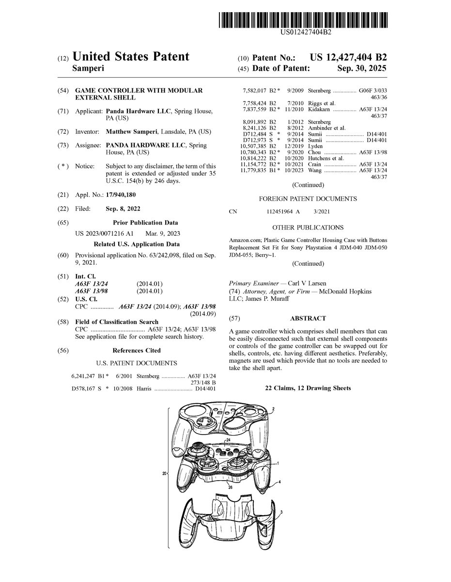
FIG.1is a perspective view of a game controller20which is in accordance with an embodiment of the present invention. As shown, the game controller20includes sections22which a user grips with his or her palms. Additionally, the game controller20includes several controls9,10with which the user interacts while gaming (i.e., using his or her fingers or thumb). As shown, these controls9,10may include things like buttons, analog sticks (i.e., joysticks), directional pads, triggers, etc. As shown, removable gates8are preferably provided on the game controller20, proximate each analog stick9for effectively dictating where the stick9ultimately ends up when being moved in that general direction.
FIG.2is an exploded view of the game controller20that is shown inFIG.1. As shown inFIG.2, the game controller20preferably comprises an internal core structure1that is surrounded by an outer shell that comprises an outer top shell2and an outer bottom shell3. The two outer shell components2and3come together to effectively surround and protect the internal core structure1that is disposed therein (to provide what is shown inFIG.1). As shown inFIG.2, preferably the internal core structure1comprises a stabilizing lip4which goes along the entire perimeter of the internal core structure1. The lip4and its purpose will be described more fully later hereinbelow.
FIG.3is a top view of the outer top shell2of the game controller20, whileFIG.4is a bottom view of the outer bottom shell3. As shown inFIGS.3and4, both outer shells2and3have user interface feature holes5for receiving controls9,10of the game controller20such that they extend therethrough (seeFIG.1) and allow the user to have access.
FIG.5is a bottom view of the inner shell1of the game controller20. As shown, preferably the bottom of the inner shell1includes internal mode switches, buttons and/or knobs6for setting the mode related to corresponding controls9,10that are provided on the top of the inner shell (as shown inFIGS.1and6). As shown inFIG.5, preferably the bottom of the inner shell1also includes removable mounting plates7, removable buttons10, and preferably an edge of the bottom inner shell provides a stabilizing lip4.
FIG.6is a top view of the inner shell1. As shown, preferably there are a plurality of removable buttons10as well as a removable mounting plate7, removable analog stick restrictive gates8, removable analog stick covers9, and preferably an edge of the top inner shell provides a stabilizing lip4.
FIG.7is a cross-sectional view which shows the lip structure that is inside the game controller20. As shown, preferably the top and bottom inner shells (24and26, respectively) contact each other (at line32) to provide structural support. Additionally, preferably the outer top shell2contacts the stabilizing lip4on the top inner shell24(at line34), and the outer bottom shell3contacts the stabilizing lip4on the bottom inner shell26(at line36), also to provide structural support. In contrast, preferably the two outer shells2and3are spaced away from each other to provide a gap38so that they do not become so tight relative to each other such that it becomes difficult to pull them apart. As shown inFIG.7, preferably there is also a gap40provided between the stabilizing lips4of the top and bottom inner shells24and26.
Preferably, as shown inFIGS.5and6, the stabilizing lip4goes all the way around the perimeter of both the top and bottom inner shell members24and26. The lip4provides the external shells2and3a support structure to sit on which prevents the external shells2and3from flexing or wobbling when they are gripped. Effectively, this lip4provides stability to the overall multi-shell design20shown inFIG.1.
With regard to how the shells2,3,24,26of the game controller20all interconnect, preferably this is achieved via magnets. By using magnets, a user can readily disassemble the game controller20(without using tools and without risking breaking any snap features) such as to swap out controls9,10or gates8, or to interact with the switches, buttons and/or knobs6(seeFIG.5) that are provided on the bottom of the inner shell1of the game controller20.
FIG.8-11show one possibility of the placement of these magnets, whereinFIG.8is a top view of the top, inner shell24,FIG.9is a top view of the top, outer shell2,FIG.10is a top view of the bottom, inner shell26, andFIG.11is a bottom view of the bottom, outer shell3.
In these Figures, the polarity of each of the magnets is indicated with either a + or a − symbol, wherein obviously opposites attract. As such, magnets A on the top, inner shell24(seeFIG.8) effectively mate with corresponding magnets A on the top, outer shell2(seeFIG.9). Likewise, magnets B on the bottom, outer shell3(seeFIG.11) effectively mate with corresponding magnets B on the bottom, inner shell26(seeFIG.10). Magnets C on the bottom, outer shell3(seeFIG.11) effectively mate with Magnets C on the top, outer shell2(seeFIG.9). Preferably, the inner shell1is shaped such that magnets C on the bottom, outer shell3(seeFIG.11) can readily mate with corresponding Magnets C on the top, outer shell2(seeFIG.9) without either the top, inner shell24(seeFIG.8) or the bottom, inner shell26(seeFIG.10) interfering with this attraction.
FIG.12is an exploded view of the top, inner shell24. As shown, a removable mask component7is provided, and all the components of the top, inner shell24can be swapped out, replaced, etc. merely by removing certain fasteners30, such as small threaded hex bolts that engage corresponding threaded bores (not specifically shown) provided inside the game controller. The mask component7allows for the secure mounting of buttons and triggers (9and10, as shown inFIG.1) to maintain optimum performance while still providing the ability to swap out controls for similar controls with different aesthetics. A similar feature7(SeeFIG.5) can be provided on the bottom shell26for removing trigger buttons10and rear buttons.
This as well as the magnetic connection between all the main components allows a user to easily customize the game controller by swapping out components, changing modes of the various controls, etc.
With regard to swapping the external shell of the game controller, the external top and bottom structures2and3can be removed from the internal controller structure1by pulling up on the edges of the external structures2and3with enough force to overcome the magnetic mounting system holding the external structures2and3to the internal controller structure1. The user can then replace the external structures2and3with a different set of external structures that share the same magnetic mounting system as the original external structures. The new external structures may have different aesthetics or have a different ergonomic shape. The new external structures can then be placed on the internal controller structure1so that the magnetic mounting system holds them securely. To do so, the external structures must be properly aligned so they sit on the internal structure stabilizing lip4, as shown inFIG.7.
With regard to replacing buttons, when the external structures2and3are removed from the controller, the user can then access the removable mounting plates7, which can be removed with, for example, a hex wrench. With the mounting plates7removed, the user can then easily pull out the buttons10and place new buttons into the controller. To reassemble the controller, the user must secure the original mounting plates7again with the screws and hex wrench, and then remount the external structures2and3as described in the swap external shell section.
With regard to replacing analog stick covers and/or gates8, the procedure to replace the analog stick covers9is the same as the procedure to replace buttons10, except instead of removing the mounting plates7, the user must remove the replaceable gates8. These gates8can also be replaced with gates that have a different shape.
With regard to changing controller settings, with the external structures2and3removed from the controller, the user can then access any number of internal mode switches, buttons and knobs6(seeFIG.5). The user can interact with those features to change how the controller functions, and then remount the external structures2and3as described in the swap external shell section.
All of the parts which can be removed from the controller, can be replaced with parts that have different aesthetics than the original.
Removing the external structures can provide access to any number of replaceable, modifiable, and/or customizable components including but not limited to: analog stick restricting gates, buttons, analog stick caps, triggers, electrical components, etc.
Removing the external structures can provide access to any number of feature mode changes which can be implemented through switches, buttons, knobs, or any other means of electrical component actuation. The feature mode changes can include but are not limited to, turning on and off rumble motors, turning on and off individual button functionality, calibrating analog inputs, returning the controller to factory default settings, adjusting analog input functionalities, adjusting digital input functionalities, etc.
In other words, not only can the external top and bottom structures be swapped out with structures that have a differently shape (ergonomics) or different appearance (aesthetics: color, artwork, etc.), but removing the external structures provides access to the internal structure, which can be modified or replaced, without negatively effecting the performance of the controller, or external aesthetics.
The embodiment of the present invention described hereinabove not only enables the user to make changes to their own controller's ergonomics and aesthetics, but the magnetic connection makes it simple to do so without requiring a full disassembly of the gaming controller or risking damage to the controller. The embodiment also allows for the full shape of the external shell to be changed, not simply made thicker, while retaining the feel/texture of the original material. The ability to customize the shape of the controller by swapping out the external structure allows for the user to change the controller that has the functionality they prefer to also have the most comfortable form factor for the individual user. This can lead to a more enjoyable gaming experience and lowers the risk of repetitive strain injury from using a controller that can cause pain when being used for extended periods of time because of ergonomic incompatibility with the user.
With regard to modularity, with the external top and bottom structures of the controller removed, the user is provided easy access to make changes or replacements to the inner components of the controller. The top and bottom structures and then be replaced without any effect to the functionality of the controller. This enables customization of analog stick, buttons, analog stick restricting gates, electrical components, etc. Furthermore, this provides access to any number of performance mode changing input devices (switches, knobs, buttons, etc.) that can be used to fine tune the performance of the controller to the users' preference. Having these input devices only accessible after removing the external structures, ensures the user cannot accidentally trigger them while playing, and allows for more freedom in the ergonomic design of the external structures.
Using magnets to mate the external shells to the internal structure allows for the simplest method of swapping out external shells. Using any fastener requires the use of a tool. Another tool-less method is using snap-fits. However, snap-fits wear down the more that they are used. Additionally, the act of removing the outer shells that are held together with snap-fits can be cumbersome, often requiring a tool to pry the snaps apart which can then damage the outer shells. Using magnets simplifies removing the external shells by not requiring any mechanical unsnapping. Additionally, if both the internal and external shells have magnets of opposite polarity, those magnets exerting their magnetic force on each other, will keep the magnetic strength of the magnets from degrading over time, providing greater longevity than snap-fits.
Using magnets to mate the external shells to the internal structure, in addition to the mating lip and guides, provides greater stability than just using guides to connect the internal structure and the external structure. If only the external shells snap fit together, the only mating features between the external and internal shells would be guides and slots for those guides to go into. While the guides would help to create proper alignment, they will still allow for some shift from side to side in their slots, and definitely allow for vertical shifting. As the snaps holding the external shells wear down (or if the plastic shells are warped at all), the internal shell may be able to move within the external shells. The outer and inner shells need to have constant force holding them together so they act as one part when they are connected. The embodiment disclosed herein uses magnets to connect the external shells to the internal shells, as well as the external shells to each other. A direct force holding the external and internal shells together is more secure than an indirect force that can wear down over time.
Overall, the concept and method disclosed herein of having removable exterior shells (for the purpose of customizing aesthetics and ergonomics) is user friendly in how the shells are removed, structurally secure when the exterior shells are mounted to the internal shells, provides a structurally sound method with a long lifespan for mounting the external shells to the internal shells over time, allowing for many total swaps, and provides good customization possibilities in allowing for buttons, triggers, sticks, and other actuators to be swapped out while maintaining secure strong connections when mounted.
While a specific embodiment of the invention has been shown and described, it is envisioned that those skilled in the art may devise various modifications without departing from the spirit and scope of the present invention.
Claims
- A game controller comprising: at least one control configured for user-interaction;an outer shell configured to be gripped;magnets inside the game controller, wherein the magnets hold the outer shell together;and, an internal core structure, wherein the outer shell comprises a top shell and a bottom shell, wherein the internal core structure comprises an inner shell, said inner shell comprising a top inner shell and a bottom inner shell, said top inner shell comprising an edge, wherein the edge of the top inner shell provides a stabilizing lip, said bottom inner shell comprising an edge, wherein the edge of the bottom inner shell provides a stabilizing lip, wherein the stabilizing lip on the top inner shell is spaced away from the stabilizing lip on the bottom inner shell, wherein the top inner shell contacts the bottom inner shell to provide structural support, and wherein the top shell and the bottom shell are spaced away from each other.
- A game controller as recited in claim 1, wherein the at least one control comprises an analog joystick, wherein the game controller further comprises at least one removable gate proximate said analog joystick.
- A game controller as recited in claim 1, wherein the outer shell covers and protects the internal core structure.
- A game controller as recited in claim 3, wherein the internal core structure comprises a perimeter and the stabilizing lip goes along the perimeter.
- A game controller as recited in claim 3, wherein the bottom of the inner shell comprises internal mode switches, buttons and/or knobs for setting a mode related to corresponding controls that are provided on the top of the inner shell.
- A game controller as recited in claim 3, wherein the bottom of the inner shell comprises removable mounting plates and removable buttons.
- A game controller as recited in claim 1, wherein both the top shell and the bottom shell comprise user interface feature holes configured to receive controls of the game controller such that the controls extend through the user interface feature holes to allow access.
- A game controller as recited in claim 1, further comprising a plurality of removable buttons, a removable mounting plate, removable analog stick restrictive gates, and removable analog stick covers.
- A game controller as recited in claim 1, wherein magnets on the top inner shell mate with corresponding magnets on the top shell, wherein magnets on the bottom shell mate with corresponding magnets on the bottom inner shell, wherein magnets on the bottom shell mate with magnets on the top shell, wherein the inner shell is shaped such that magnets on the bottom shell mate with corresponding magnets on the top shell without the inner shell interfering.
- A game controller as recited in claim 1, wherein the outer shell covers and protects the internal core structure, further comprising a removable mask component, wherein all components of the top of the inner shell are swappable by removing fasteners provided inside the game controller, wherein the removable mask component allows for the secure mounting of buttons and triggers while providing an ability to swap out controls for similar controls with different aesthetics.
- A game controller comprising: at least one control configured for user-interaction;an outer shell configured to be gripped, having a top shell and a bottom shell;magnets inside the game controller, wherein the magnets hold the outer shell together;and, an internal core structure, wherein the outer shell surrounds the internal core structure, wherein the internal core structure comprises an inner shell, said inner shell comprising a top inner shell and a bottom inner shell, wherein magnets on the top inner shell mate with corresponding magnets on the top shell, wherein magnets on the bottom shell mate with corresponding magnets on the bottom inner shell, wherein magnets on the bottom shell mate with magnets on the top shell, wherein the inner shell is shaped such that magnets on the bottom shell mate with corresponding magnets on the top shell without the inner shell interfering.
- A game controller as recited in claim 11, wherein the at least one control comprises an analog joystick, wherein the game controller further comprises at least one removable gate proximate said analog joystick.
- A game controller as recited in claim 11, wherein the outer shell covers and protects the internal core structure.
- A game controller as recited in claim 11, wherein the internal core structure comprises a perimeter and a stabilizing lip which goes along the perimeter.
- A game controller as recited in claim 11, wherein both the top shell and the bottom shell comprise user interface feature holes configured to receive controls of the game controller such that the controls extend through the user interface feature holes to allow access.
- A game controller as recited in claim 11, wherein the bottom of the inner shell comprises internal mode switches, buttons and/or knobs for setting a mode related to corresponding controls that are provided on the top of the inner shell.
- A game controller as recited in claim 11, wherein the bottom of the inner shell comprises removable mounting plates and removable buttons.
- A game controller as recited in claim 11, wherein each of said top inner shell and bottom inner shell comprising an edge, wherein the edge of each of the top inner shell and bottom inner shell provides a stabilizing lip.
- A game controller as recited in claim 18, wherein the stabilizing lip of the top inner shell is spaced away from the stabilizing lip of the bottom inner shell.
- A game controller as recited in claim 11, further comprising a plurality of removable buttons, a removable mounting plate, removable analog stick restrictive gates, and removable analog stick covers.
- A game controller as recited in claim 11, wherein the top inner shell contacts the bottom inner shell to provide structural support.
- A game controller as recited in claim 11 further comprising a removable mask component, wherein all components of the top of the inner shell are swappable by removing fasteners provided inside the game controller, wherein the removable mask component allows for the secure mounting of buttons and triggers while providing an ability to swap out controls for similar controls with different aesthetics.
Disclaimer: Data collected from the USPTO and may be malformed, incomplete, and/or otherwise inaccurate.