U.S. Pat. No. 12,419,426
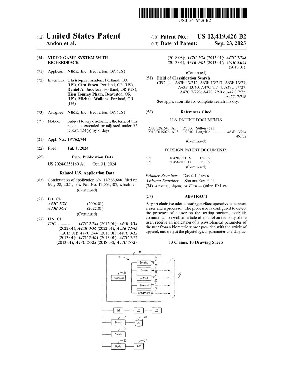
VIDEO GAME SYSTEM WITH BIOFEEDBACK
AssigneeNIKE, Inc.
Issue DateJuly 3, 2024
On July 3, 2024, the U.S. Patent Office issued U.S. Pat. No. 12,419,426 to NIKE, Inc. The patent concerns a “sport chair” that would connect with a receiver attached to a video game player’s body in order to monitor biometrics during play. Nike’s potential foray into video gaming represented by this patent combines the company’s expertise in sporting goods with the type of data collection that some game players might find immersive.
One of the patented system’s goals is described in the Specification itself: “[To] receive an indication of a physiological parameter of the user from a biometric sensor provided with the article of apparel … and output the physiological parameter to a display.” Essentially, this just means the apparatus could track a user’s heart rate and utilize the data in a video game. Such a system demonstrates ongoing interest from major retail brands like Nike in experimenting with video games and tech demos to boost the profile of their products.
Illustrative Claim:
1. A video game system comprising: an input controller;
a display;
a biometric sensor configured to sense at least one of a heart rate or a respiration rate of a user;
a processor configured to: receive input from the input controller;
receive physiological data from the biometric sensor;
control the display to present a game environment;
alter at least one aspect of the game based on the physiological data, wherein: an increase in the sensed heart rate or the sensed respiration rate is operative to cause at least one of: a decrease in focus of the display;
a decrease in an amount of peripheral vision displayed via the display;
or an increase in an amount of jitter in the controller.
Illustrative Figure
Abstract
A sport chair includes a seating surface operative to support a user and a processor. The processor is configured to detect the presence of a user on the seating surface, establish communication with an article of apparel on the body of the user, receive an indication of a physiological parameter of the user from a biometric sensor provided with the article of apparel, and output the physiological parameter to a display.
Description
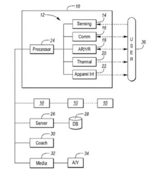
DETAILED DESCRIPTION Referring to the drawings, wherein like reference numerals are used to identify like or identical components in the various views,FIG.2illustrates a schematic embodiment of a smart chair10that includes one or more integrated electronic aspects (generally at12) that may be useful in a sporting or e-sporting environment. As shown, the chair10may include, for example, one or more sensors or sensing capabilities14, bi-directional or uni-directional audio communication systems16, a visual display system18such as an augmented or virtual reality display, one or more conductive and/or convective thermal transducers20, and/or apparel integration capabilities22. Each electronic aspect12may be directly controlled or in communication with a processor24, which in some embodiments may be in remote communication with one or more other smart chairs10, a remote storage server26/database28, a remote coaching terminal30, and/or a media production device32that interfaces with external audio/visual (A/V) facilities34. From a structural perspective, it is desirable to construct the chair10to be as ergonomic as possible and designed to support the user36in a natural body pose that minimizes both average and maximum contact pressures between the user36and the chair10. In some embodiments, an ideal, ergonomic chair design may include a mixed material construction that provides structure and form to the chair10while also serving to cradle the user36and maximize comfort. For example, in one configuration, such as shown inFIGS.3-4, the chair10may include a rigid outer structure40that surrounds and supports a more compliant inner seating surface42. In some embodiments, the rigid outer structure40may underlie the compliant inner seating surface42, while in other embodiments, such as shown inFIGS.3-4, the outer structure40and inner seating surface42may cooperate to define a continuous surface44. The compliant inter seating surface42may be particularly configured to conform to the contours of the user's body when the user36sits within the chair10. In this manner, the surface area that is in flush contact between ...
DETAILED DESCRIPTION
Referring to the drawings, wherein like reference numerals are used to identify like or identical components in the various views,FIG.2illustrates a schematic embodiment of a smart chair10that includes one or more integrated electronic aspects (generally at12) that may be useful in a sporting or e-sporting environment. As shown, the chair10may include, for example, one or more sensors or sensing capabilities14, bi-directional or uni-directional audio communication systems16, a visual display system18such as an augmented or virtual reality display, one or more conductive and/or convective thermal transducers20, and/or apparel integration capabilities22. Each electronic aspect12may be directly controlled or in communication with a processor24, which in some embodiments may be in remote communication with one or more other smart chairs10, a remote storage server26/database28, a remote coaching terminal30, and/or a media production device32that interfaces with external audio/visual (A/V) facilities34.
From a structural perspective, it is desirable to construct the chair10to be as ergonomic as possible and designed to support the user36in a natural body pose that minimizes both average and maximum contact pressures between the user36and the chair10. In some embodiments, an ideal, ergonomic chair design may include a mixed material construction that provides structure and form to the chair10while also serving to cradle the user36and maximize comfort. For example, in one configuration, such as shown inFIGS.3-4, the chair10may include a rigid outer structure40that surrounds and supports a more compliant inner seating surface42. In some embodiments, the rigid outer structure40may underlie the compliant inner seating surface42, while in other embodiments, such as shown inFIGS.3-4, the outer structure40and inner seating surface42may cooperate to define a continuous surface44. The compliant inter seating surface42may be particularly configured to conform to the contours of the user's body when the user36sits within the chair10. In this manner, the surface area that is in flush contact between the user36and the chair10is maximized.
FIGS.5A and5Bschematically illustrate the differences in contact surface area between a chair such as shown inFIG.1and the chair10shown inFIG.3. InFIG.5A, it is clear that the traditional chair only establishes contact with the user36across a narrow surface area46aof the mid-back and upper legs. Conversely,FIG.5Billustrates an embodiment where the entire posterior surface46bof the user36is in contact with the chair10. By supporting more of the user, the chair10provides better ergonomics, and permits the user36to more completely relax into the chair and rest/recover if necessary. WhileFIG.3illustrates a somewhat reclined embodiment of the present chair, it may also be possible for the chair to be more upright or to assume other postures that provide improved contact pressures and ergonomic qualities above the standard folding chair ofFIG.1.
As schematically illustrated inFIG.6, and also mentioned above, in some embodiments, the chair10may include various sensing capabilities14that aid in determining a user's identity (i.e., identity sensing50) and/or the real-time health of the user36(i.e., health sensing52). By knowing the identity of the individual in/on the chair10, the processor24may customize certain performance attributes of the chair10to suit that user36and/or to coordinate other sensed data for third-party display and/or aggregation. Health sensing52may generally include the monitoring of certain biometrics, which may be useful in determining future game strategy (from a coaching perspective), establishing trends, and/or for third-party infographic display.
To enable identity sensing50the chair10may include an RFID reader for reading an RFID chip coupled with the user36or user's apparel, a camera equipped with facial recognition software, a finger print scanner, a keypad, or other such sensory means. Each of these identity-sensing modalities generally requires the chair10to sense some identifying attribute of the user36. Once sensed, the respective sensor may convey information related to the attribute to the processor24, which may draw the appropriate inference as to the user's identity.
In some configurations, health sensing52may include real-time monitoring of hydration, weight, heart rate, respiration, galvanic skin response, or other such biometrics. For example, in one configuration, the chair10may include one or more load cells to determine the real-time weight of the user36. Given that rapid weight fluctuations are largely attributable to changes in hydration, if the processor24determines, via the load cell, that a user's weight has decreased by more than a predetermined amount or percentage throughout the course of the event, the processor24may conclude that the user36is dehydrated, and may alert the user36to drink fluid. Such an indication of dehydration may be provided, for example, by illuminating a light visible to the user36or visible to personnel in close proximity to the chair10(e.g., team personnel or training staff). As a different proxy for hydration, the processor24may further be configured to monitor changes in the weight of one or more water bottles, for example, via one or more strain gauges or load cells associated with a cup holder. In this manner, the processor24may track the total fluid intake of the user36.
Likewise, in some configurations, the chair10may include one or more integrated sensors that are capable of determining the user's heart rate, respiration rate, and/or galvanic skin response. These sensors may include one or more electrodes, load cells, strain gauges, light emitting diodes, optical sensors, or other such sensors that may be known to monitor such parameters. Furthermore, these sensors may be integrated within the surface of the chair, underneath a moisture barrier layer, and/or underneath a cushioning layer. In other embodiments, as further described below, one or more of the sensors may be embedded in the user's apparel and/or in a wearable device or strap in direct communication with the user's skin.
Once coordinated with a user's identity, the player-specific health data54may then, for example, be logged or recorded by the server26and/or by an associated database28for the purpose of trend analysis and real-time detection of trend deviations. Furthermore, the real-time health data54and/or trend data56may then be streamed to a remote coaching terminal30(such as generally shown inFIG.7), and/or a media production device32, where it may be displayed for informational purposes. For example, in some embodiments, coaching/training staff may use the player-specific health data54to make assessments regarding whether the user36is sufficiently rested/recovered to resume competition. Likewise, media production staff may incorporate the player-specific health data54and/or trend data56into a live or televised audio/visual broadcast (e.g., via A/V facilities34). In still other embodiments, the health data54and trend data56may be presented directly to the user via a display.
In yet another embodiment, player-specific health data54and/or trend data56may further be used in an e-sports context as part of the game play. For example, a user's real-time sensed physiologic response during a game may be used as an input to control visual focus and/or controller sensitivity or jitter. In such an embodiment, tense or stressful encounters (as assessed, for example, by heart rate or respiration rate) may result in a less-focused display, loss of a degree of peripheral vision, or increased jitter in the controls. As such, a gamer that is able to control their physiological response may have an advantage.
As schematically illustrated inFIG.7, and also mentioned above, in some embodiments, the chair10may include various audio communication systems16that aid in facilitating audible communication between two or more users36and/or between one or more users36and local or remote coaching staff60(i.e., over a data connection62). In such an embodiment the audio communication systems16may include at least a speaker64provided in connection with each respective chair10. Likewise the audio communication system16may further include at least one microphone or other audio input device associated with a remote coaching terminal30and/or one or more of the provided chairs10. In this manner, the audio communication systems16may facilitate player-to-player communication and/or communication between users and coaching staff. Player-to-player communication may be particularly beneficial in noisy stadium/arena environments, or in sports where players are constrained to sit in a linear arrangement. Likewise, coach-to-player communication may better enable in-game adjustments by facilitating player-specific or team strategy advice to any one or more users36or groups of users36.
In some embodiments, the speaker64and/or audio communication system16may be operative to provide a noise cancellation function to each respective user36. Such a noise cancelling capability may be useful in loud arenas or stadiums to provide the user36with both a sense of calm and relaxation, as well as to better facilitate communications between players and between players and coaching staff. In such an embodiment, the chair10may be provided with a microphone that receives audible background/stadium noise. The processor24may receive the signal from the microphone, and direct the speaker64to broadcast an out of phase audio wave to the user36that destructively interferes with and/or lessens the magnitude of the ambient noise. In some embodiments, this may be better provided for with a chair10having a wraparound head support.
In addition to purely audio communication/advice, many athletes rely on visual information and/or demonstratives to better understand in-game strategy and tendencies of the opposing team. As such, in some embodiments, the smart chair10may include a visual display system18that may incorporate an augmented reality (AR) field of view and/or one or more immersive or partially immersive displays (e.g., akin to virtual reality (VR)). These display systems18may be used by coaching staff to replay previous game sequences, to diagram future game sequences, to provide overhead and/or perspective views of live and/or recorded play, to enhance a user's real-time view of live play. Furthermore, in some embodiments, the visual display system18may be used to relax a user36following a period of strenuous activity and/or may be used to energize a player before entering the game/competition.
Specifically, as shown inFIG.7, in some embodiments, the visual display system18may include a graphical display70that may be worn on or over a portion of the user's head72, and particularly in front of the user's eyes. In some embodiments the display may be embodied in a helmet, visor, or other head covering element associated with the chair10. Alternatively, the display70may be embodied in glasses, goggles, or other discrete lenses that may be separate from the chair10. In either embodiment, it may be preferable for the graphical display70may include a discrete visual display for each of the user's eyes (or capabilities to project stereoscopic visuals separately to each eye) in order to provide a stereoscopic display to the user36.
In an AR configuration, the graphical display70may include a substantially transparent lens that is operative to provide one or more visual elements within the field of view of the user36. The display70may include, for example, a transparent lens that receives a projected image from an adjacently positioned projector, a selectively emitting display (e.g., an OLED display), and/or a display that can selectively alter light transmission (e.g., an LCD). Furthermore, the graphical display70may include a view-tracking system that can detect and/or understand the user's real-time field of view by looking outward, such as using a camera, looking inward to track the user's eye motion, and/or by understanding the real-time position and orientation of the display70. Examples of graphical display technology that may be used with the present system for Augmented Reality presentation are detailed in U.S. Patent Application No. 2014/0160001, which is incorporated by reference in its entirety.
In a VR configuration, the graphical display70may generally be non-transparent such that the display blocks the user's perception of their surroundings external to the display. In such an embodiment, the display70may include, for example, a projected display on an opaque or translucent surface, an emitting display with an opaque back-surface, or a backlit, selectively transmissive display such as an LCD or LED display. In some embodiments, VR and AR may be accomplished using the same device, and/or selectively over discrete portions of the device, for example, using a selectively dimmable electrochromic layer disposed behind an emitting display such as an OLED display. An example of such a combined VR/AR display is described in U.S. Patent Application No. 2016/0055822, which is incorporated by reference in its entirety.
FIG.8schematically illustrates an embodiment of a mixed-reality view80, such as may be seen through the graphical display70shown inFIG.7. In this embodiment, a diagrammatic view82of the court is overlaid within the user's real-time field of view84to more accurately illustrate player movement that lead to the current live action. More specifically, in some embodiments, this top view of the court may illustrate all player positions using either live images or diagrammatic symbols86, and may further include player history lines88to represent player motion for a predetermined amount of preceding time. In some embodiments, the view80may be dynamically reconfigurable, and may allocate a portion of the view80for replay video (i.e., replay window90), which may selectively be fed to the display70via the coaching terminal30. Additionally, in some embodiments, the display70may superimpose a position indicator92coincidently with or marginally above the floor94to highlight real-time player position. Similar to the diagrammatic view82, player history lines88may trail the position indicator92to illustrate player motion. During time outs, for example, the relative sizing of the diagrammatic view82and/or replay window90may be adjusted/enlarged to provide enhanced coaching and strategy illustration.
WhileFIGS.7-8illustrate the use of audio and video capabilities16,18in connection with the sport of basketball, they may be readily suited for other sports and e-sports as well. For example, the current state of the art for in-game coaching in the sport of American Football includes small groups of players collectively reviewing printed images and/or replay video provided on tablet displays. The present chair technology would provide a significant benefit to coaching and team integration while enabling the players to relax in a seated manner while focusing on the coaching advice. Furthermore, as noted above, the present chair10may include a plurality of thermal transducers20for maintaining the athlete's body in a ready state (which is typically not possible if players are required to huddle around a singular display). In an e-sporting context, the audio and video capabilities16,18may be used to provide an immersive and/or semi immersive environment for the gaming competitor, while enabling the competitor to outwardly communicate and/or for the competitor's personal commentary to be broadcast to a larger audience.
In a traditional sporting context,FIG.9schematically illustrates an embodiment of a smart chair10with a plurality of thermal transducers20that are configured to actively maintain the temperatures of various muscle groups within the user's body in a “warmed-up” state, and one or more systems that are adapted to aid in reducing/regulating the user's core body temperature and/or lessening feelings of fatigue/exhaustion.
As shown inFIGS.9-10, in some embodiments, the inner seating surface42of the chair10includes a plurality of discrete thermal zones114that are each adapted to actively apply heat and/or apply cooling to the user36via conductive heat transfer. As used herein, “applying heat” or “heating” involves controlling the respective thermal zone114to generate and outwardly transfer a thermal flux to the user36(i.e., a heat source), whereas “applying cooling” or “cooling” involves controlling the respective thermal zone114to absorb and inwardly receive a thermal flux from the user36(i.e., a heat sink).
Each thermal zone114includes one or more working elements116that are configured to actively generate and/or absorb thermal energy, and a user-facing contact surface118that facilitates heat transfer between the working element116and the user36. In one configuration, such as better shown inFIG.10, the working element116may be, for example, a thermoelectric cooler, such as a Peltier device120, and the contact surface118may include the user-facing outer surface of the Peltier device120. As is well understood in the art, Peltier devices are solid-state devices that can controllably vary a temperature gradient across a thickness of the device120in response to an applied electric current122(schematically shown inFIG.9). Beneficially, these devices120can be used to either heat or cool a desired surface. For example, if a current is applied to the Peltier device120, the contact surface118may thermally heat while an opposing side may thermally cool. Conversely if an opposite current is applied to the Peltier device120, the contact surface may thermally cool while an opposing side may thermally heat.
To maximize the flexibility and utility of the chair10, it is preferable for each thermal zone114to be capable of both applying heat and applying cooling to the user, such as may be provided by a Peltier device120. Given this versatility, the chair10may be used to actively warm-up a user36prior to an event, maintain the user36in a state of readiness during breaks in the event, and/or cool down the user36after the event simply by altering the heating/cooling profile across the various thermal zones114.
In other embodiments, select zones may be configured strictly to apply heat (e.g., such as zones that are dedicated for warming muscles), while other zones may be configured strictly to apply cooling (e.g., zones for cooling/aiding to regulate the user's core temperature). Dedicated heating zones may utilize a working element116such as, for example, a resistive heating element or a bladder filled with a heated liquid. Likewise dedicated cooling zones may utilize a working element116such as, for example, an air-cooled heatsink, a refrigeration system, or a cryogenic fluid, a bladder filled with a cooled liquid. In a further embodiment, a dedicated cooling zone may incorporate the use of a large mass with a high thermal capacity held at a temperature lower than the user's skin (e.g., a large block of steel, aluminum, or vessel of water).
In order to maintain a user36at an optimal state of athletic readiness, the chair10is operative to independently and selectively control the temperature output of each of the plurality of thermal zones114. By doing so, the chair10may attempt to regulate different local areas of the user's body at their respective optimal temperatures. To accomplish this independent and selective control, the processor24may be in communication with each of the plurality of thermal zones114. The processor24is configured to execute one or more software/firmware algorithms stored thereon, or readily accessible thereto to understand and independently control the temperature of each respective thermal zone114.
In one configuration, the processor24may control the temperature of each respective thermal zone114in an open loop manner. For example, the processor24may receive an indication of a desired amount of thermal flux for each zone114, and may operate the respective working elements116to respond accordingly. In a system where the working element116is a Peltier device120, the processor24may directly supply a current122to each device120in response to the received indication of desired thermal flux. The received indication of desired thermal flux may be a qualitative measure of a desired amount of heat/cooling that should be applied via the zone114, and may be input by the user36via one or more digital or analog input devices. Alternatively, the desired amount of thermal flux may be preprogrammed into the processor24based on the desired use of the chair10(e.g., according to the sport, athletic intensity, sporting environment, and/or the anticipated duration of the rest).
While open loop temperature control presents an easily implemented solution, a more preferred strategy involves the use of closed loop temperature control. In a closed loop temperature control strategy, each thermal zone114may include one or more temperature sensors132that are operative to output a signal134indicative of the temperature of the contact surface118and/or the temperature of the user36immediately proximate to the contact surface118. With this feedback, the processor24may modulate the output of the working element116(e.g., by varying the current122provided to the working element116) in an attempt to minimize the difference between the sensed temperature and a specified set point temperature. In one configuration, the user36may directly input their desired temperature set point for each respective thermal zone114. In another configuration, the set point temperatures may either be automatically selected by the processor24or may be preprogrammed into the processor24according to the nature of the sport and the environment in which the sport is played.
In a preferred embodiment, the processor24may automatically attempt to provide optimal thermal relief to the user, while attempting to maintain the user's various muscle temperatures at their respectively optimal levels for the activity that the user36is participating in. To accomplish this, the thermal zones114are desirably located such that they align with and directly contact the user36at or near the muscle group and/or body region that they are intended to apply heat or cooling too. For example, if the chair10is used in connection with the sport of basketball (e.g., for use before the start of a game, or following a player substitution), thermal zones114may desirably be placed to contact and be in direct thermal communication with the user's gluteal muscles, muscles of the hamstring (i.e. semitendinosus, semimembranosus, and/or biceps femoris), and/or the muscles of the calf (i.e., gastrocnemius). It may also be beneficial to place thermal zones114for direct contact with muscles of the back (i.e., trapezius, rhomboideus, erector spinae, serratus, abdominal obliques, and/or latissimus dorsi), shoulders (i.e., deltoids) and/or arms (e.g., triceps).
For the purpose of maintaining muscle temperature at an optimal level,FIGS.9-10schematically illustrate a first plurality of thermal zones140that are positioned for direct contact with the upper back (e.g. the rhomboid muscles), a second plurality of thermal zones142that are positioned for direct contact with the gluteal muscles and/or the muscles of the hamstring, and third plurality of thermal zones144that are positioned for direct contact with the muscles of the calf. In each instance, it is desirable for the processor24to maintain the respectively adjacent muscles at a temperature that is from about 2° C. to about 4° C. above their natural resting temperature, which may be achieved by controlling the temperature of the contact surface118to a set point temperature it is at or marginally above the desired muscle temperature.
While maintaining muscles at an elevated temperature can be useful in maintaining the muscles in a state of readiness, which both reduces the likelihood of future injury and improves muscle performance/power, heating can be detrimental to the longer-term endurance of the athlete and to the psychological perception of thermal relief following a period of exertion. Therefore, in an effort to alleviate fatigue, enhance user comfort, and reduce thermoregulatory stress within the user's body, the present chair10can apply cooling to the user36in one or more of a variety of forms.
First, the chair may include a thermal zone146aligned with the user's spine and/or neck that is configured to actively sink thermal energy from the user36. The neck and spine regions carry a significant amount of blood flow, yet have minimal amount of muscle mass that are at risk of cramping or negatively affecting athletic performance if cooled. As such, by applying cooling the spine and/or neck, the chair10may aid the user's body in managing its core temperature (i.e., lessening the thermoregulatory strain experienced by the body), while also providing psychological benefits such as the feelings of rest, recovery, and/or thermal relief. In one configuration, applying cooling to the spine and/or neck may be performed in a controlled manner to avoid any adverse effects on muscle temperature even despite the application of external heating.
The chair10may further provide cooling to the user36by way of a convective cooling system150that directs airflow152at and across the head and/or face of the user, such as schematically shown inFIGS.9and11. While it is uncertain whether convective cooling of the head and/or face has a significant impact on core body temperature, it has been shown to provide the beneficial effects of prolonging the average time to fatigue and reducing the user's perceived level of total exertion. Furthermore, it has been found that in some circumstances, cooling of the face can have distinct performance advantages during aerobic activity.
As shown inFIG.9, and more clearly inFIG.11, in some embodiments, the convective cooling system150may include an air plenum154that is configured to direct airflow152at the head and/or face of the user36. In one configuration, the air plenum154includes one or more orifices, slots, or other such vents156that permit pressurized air to exit the plenum154and be directed toward the head/face of the user36. In one configuration, it may be preferable for the air to be delivered in a laminar manner, which may enable the exiting airflow152to closely follow the contours of the user's head and face. While it is preferred for the one or more orifices, slots, or other such vents156to be located sufficiently forward relative to the user's head (e.g., anterior to the coronal plane) for the airflow152to be directed across the user's face, in some embodiments, the nature of the flow (e.g., laminar/boundary following) may enable face cooling even if the vents156are located further rearward.
As schematically shown inFIG.9, the convective cooling system150may further include one or more fans158or other blower devices configured to move air within the system150. For the purpose of cooling the airflow152prior to directing it at the user, the convective cooling system150may further include one or more refrigeration devices160that are disposed within the path of the air prior to the air exiting the vents156. In one configuration, the refrigeration device160may utilize, for example, refrigerant or evaporative cooler to cool the flowing air. In another configuration, the refrigeration device160may utilize and/or include the reverse surface of one or more of the Peltier devices120that are being used to warm the user's muscle. Finally, as shown inFIG.11, the convective cooling system150may further include any required ducting162that is needed to carry airflow from the fan158to the plenum154.
In some embodiments, the chair10may further include a convective humidity management system that is operative to manage the humidity within the microclimate immediately surrounding the user36. For example, following a period of intensive activity, the user's body may be exceedingly covered in sweat. The humidity management system may direct airflow around the body of the user36in a manner that leads to the evaporation of the sweat and/or aids in in reducing any increase in local humidity that is attributable to evaporated sweat. The humidity management system may utilize the plenum154and/or micro channels extending through the inner seating surface42of the chair10to direct a flow of air over the user's body. In one configuration, the body-directed airflow may be heated (e.g., via a heating element) to avoid having a noticeable chilling effect on the user's skin/muscles. Alternatively, in some embodiments, the body-directed airflow may be at an ambient temperature or cooled below an ambient temperature in an effort to cool the user36(if so desired) and/or to provide a psychological benefit of being refreshed.
In a configuration where a particular seating surface42is likely to receive a plurality of different users throughout the athletic event, it is of particular importance for the chair to have sufficient compliance to comfortably and ergonomically receive users having differing body types. Likewise, the plurality of thermal zones114should be located such that they contact the desired muscle groups/body locations for a range of body types/sizes.
To provide the most optimal thermoregulatory effect across a plurality of different users/body sizes, in one configuration the plurality of thermal zones114may be dynamically assigned and/or constructed based on an understanding of the user's specific anatomy. For example, a plurality of discrete working elements116may be disposed across the entire inner seating surface42of the chair10(or across a substantial portion thereof). Upon receiving the user36into/onto the chair10, the processor24may intelligently define the plurality of thermal zones114by grouping adjacent sets of working elements116according to that user's specific anatomy.
In one configuration, the processor24may determine the user's anatomical makeup by monitoring the contact pressure between the user36and the chair10, for example, using a plurality of strain gauges or load cells integrated into the seating surface42and/or working elements116. In another configuration, the processor24may determine the user's anatomical makeup by receiving an indication of the user's identity (e.g., via identity sensing50capabilities), and then retrieving that user's anatomical proportions from an electronic database.
In yet another configuration, instead of full dynamic construction of the thermal zones114, certain predefined thermal zones114may be selectively modified if a user's anatomy dictates such modification. For example, as shown inFIG.10the different thermal zones114maybe sized/located to accommodate users at both large and small ends of the expected user36size (e.g., 95thand 5thpercentile anatomy). If a particular user's anatomy does not require the entire array, individual working elements116may be selectively deactivated upon the processor24learning the user's identity.
Referring again toFIG.2, in some embodiments, the chair10may include one or more electronic aspects that integrate with a user's footwear or apparel (i.e., apparel integration22). For example, if the user36is wearing shoes or apparel with auto tensioning mechanisms, then the chair10may cause the user's shoes/apparel to relax when the user36initially sits down, and re-tension when the user36is about to enter/re-enter competition. Examples of auto-tensioning footwear and apparel are described in U.S. Pat. Nos. 8,046,937 and 9,365,387, which are hereby incorporated by reference in their entirety. Such devices may generally operate by electronically spooling or constricting one or more tensioning fibers provided within the article. As the fibers are drawn in, they may cause the article to apply a generally constrictive force to a portion of the user's body. While this force can be beneficial during competition, it can sometimes be perceived as uncomfortable when the user36is attempting to relax.
FIG.12schematically illustrates one embodiment of an apparel integration schema. As shown, the chair10is in close contact with an article of apparel and/or footwear170(generally “apparel170”) that is being worn by a user36. The apparel170includes a motor172(or other electrically actuated constriction element, such as shape memory alloy, electroactive polymers, or the like) that is operative to selectively tension at least one fiber174provided in the apparel170, wherein tensioning or relaxing the fiber174causes the apparel170to constrict or relax about the user36. Examples of apparel170that may utilize such selective constriction includes compression shirts, compression arm or leg sleeves, compression shorts, knee braces, wrist braces, ankle braces, foot braces, gloves abdominal padding/braces, shoes, and the like. In some embodiments, the motor172may be powered by a battery176or other charge storing device that is carried by the apparel170. In other embodiments, the motor172may be powered by an external source, such as the chair10and/or processor24.
Upon a user36sitting into the chair10, the processor24may detect the user's presence and/or identity via the sensing capabilities14integrated into the chair10. Following this indication, the processor24may direct the motor172to unspool and/or relax the tension on the fiber174, thus causing the apparel170to lessen any constriction about the user36. The processor24may provide this instruction via a data connection178between the chair10and the apparel170. In some embodiments, this data connection may be a wired data connection that is made between electrical terminals on the chair10and mating electrical terminals integrated into the apparel170. Such terminals may include, for example, magnetic contact elements to aid in ensuring contact. In other embodiments, the data connection178may involve low power Bluetooth radios, near field communication capabilities, or other short-range wireless digital communication means.
When a user36is ready to resume play and/or stand up from the chair10, the processor24may direct the motor172to re-tension the fiber(s)174to cause the apparel170to re-constrict about the user36. In one embodiment, the processor24may understand the user's intentions to exit the chair10after receiving an exit command from the user36(e.g., the user36pressing a button indicating re-tension or exit). In another embodiment, the processor24may understand the user's intentions to exit the chair10by monitoring the user's body posture and/or contact pressures between the user36and the chair10and inferring an immanent attempt to stand. In still another embodiment, the apparel170may operate autonomously to re-tension following a break in communication or contact with the chair10(i.e., when the user fully stands from the chair10).
As further illustrated inFIG.12, in some embodiments, the processor24may receive a tension feedback signal180from the motor172indicative of the real-time tension through the fiber174and/or apparel170. The processor24may use this signal180to ensure the apparel170is adequately relaxed upon sitting, and to adaptively re-tension the apparel170when the user36is ready to resume competition. In some embodiments, adaptive tensioning may be useful to account for swelling, fluid retention, and/or changes in a user's body proportions that may occur during the competition. Said another way, if tensioning based on, for example, exerted apparel pressure against the user, the absolute size of the apparel170may be different at the start of the competition than at the end of the competition due to changes in body size.
With continued reference toFIG.12, in some embodiments, the apparel integration22features of the present chair10may include charging capabilities182for an adaptive article of apparel and/or footwear170. In some embodiments, these capabilities may include an inductive charging means that includes an inductive charging transmitter184provided on the chair10, and an inductive charging receiver186associated with and/or integrated into the apparel170. Examples of suitable charging capabilities are further described in U.S. Pat. No. 8,058,837 and U.S. Patent Application No. 2016/0345654, both of which are incorporated by reference in their entirety. The chair10may utilize the time that the user36is sitting in the chair10to ensure the battery176is at an adequate state of charge. If charging is required, the chair10may transmit a magnetic field from the inductive charging transmitter184that may be received by the inductive charging receiver186and used to replenish the stored charge in the battery176.
In some embodiments, the sensing capabilities14described above with respect toFIGS.2and6may be incorporated with the apparel integration22functionality. More specifically, the user's apparel may include one or more sensors that are held in close proximity with or in contact with the skin of the user36. These sensors may include, for example, heart rate sensors, respiration sensors, galvanic skin response sensors, RFID identity indicators, and the like. The sensors may be integrated/woven into one or more compression-fitting garments, protective padding, footwear, straps worn around the torso or other appendages, or adhesively stuck on to the user36(generally “apparel sensors”). In some configurations, the apparel sensors may include a memory device, such as a flash or EEPROM memory that can record periodic user data while the user36is engaged in the athletic competition. When the user36sits on the chair10, the chair10may communicate with these apparel sensors in a uni-directional or bi-directional manner (e.g., low power Bluetooth, NFC, etc) to receive real time user biometric information and/or biometric information that has been stored to the memory of the apparel sensor. This downloadable content may be used in the same manner as biometric data that is directly acquired by the chair10, as described above.
In some embodiments, the apparel-based sensing capabilities may include one or more accelerometers that are embedded within a user's protective padding and/or woven or otherwise integrated with the user's compression-based undergarments. Such sensing capabilities may be useful in recording the magnitude and location of any impacts or collisions that may occur during the competition. Upon the user exiting the field of play and sitting on the chair10, the recorded sensory data may be downloaded by the processor24and/or capabilities within the chair10. In such an embodiment, requiring close contact between the sensing electronics and the receiver may provide for lower weight and lower power additions to the apparel, which may receive greater athlete acceptance and lead to a greater adoption.
While the chair10described above provides benefits for an individual athlete, in some configurations, a sports team may find particular utility in providing similar benefits to more than one athlete at a given time. As such, in one configuration, a plurality of smart chairs10may be adjacently coupled to form a smart bench that includes a plurality of inner seating surfaces42, each adapted to ergonomically receive and support a different user/athlete. In one configuration, the smart bench may be a single, unitary product that includes a plurality of adjacent seating surfaces42. In another configuration, adjacent individual chairs10may be locally affixed to form a larger structure.
If used in connection with the sport of basketball, a smart bench may be adapted to receive and support, for example, up to five users/athletes or more at any particular time. The five users may include players currently checked into the game (e.g., during a timeout or break between quarters), players recovering after being substituted out of the game, and/or players awaiting imminent substitution into the game. In other examples, a smart bench for basketball may be adapted to receive and support up to two or three users/athletes (i.e., given that most teams play with a seven or eight man rotation, the two or three players waiting to enter/re-enter the game may be maintained in a warmed-up state).
While the present disclosure is primarily illustrated in connection with the sport of basketball, the present technology is equally applicable and useful with other sports, such as, but not limited to, American football, soccer, tennis, lacrosse, rugby, baseball, softball, hockey, gymnastics, stock car racing, open wheel racing, skiing, snowboarding, sprinting or other track and field events, swimming, field hockey, wrestling, mixed martial arts, boxing, cricket, or any events that involve intermittent periods of play and rest, events that are performed seated, or events that involve in-game player substitutions. Likewise, while the present chair has primary applicability with the athlete, one or more of the described smart chair aspects may be similarly applicable to spectators of any of the above-identified sports.
As used above, the “processor24” is intended to include and may be embodied as one or more distinct data processing devices, each having one or more microcontrollers or central processing units (CPU), read only memory (ROM), random access memory (RAM), electrically-erasable programmable read only memory (EEPROM), a high-speed clock, input/output (I/O) circuitry, and/or any other circuitry that may be required to perform the functions described herein. The processor24may be local to the chair10and/or may include one or more remote processors or servers. In some embodiments, the “processor24” may include and/or be in communication with one or more internet-based/cloud-based services that may provide or receive real-time data to/from the chair10and/or may control one or more performance or visual aspects of the chair10.
FIG.13schematically illustrates an embodiment of a method200of operation of the chair10from the perspective of the processor24. The method200generally begins at210with the detection of the presence of a user/athlete. As noted above, presence may be detected by monitoring, for example, one or more load cells, strain gauges, capacitive sensors, thermal sensors, or RF sensors for the presence of a user on the seating surface42.
Once a user is detected at210, using the connected hardware, the processor24may perform one or more thermal management functions (generally at202), one or more biometric sensing functions (generally at204), one or more display or communication functions (generally at206), and/or one or more apparel/footwear integration functions (generally at208).
As described above, to provide the thermal management functionality202the processor24may begin by monitoring a temperature of a user and/or the user's muscles (at212). This monitoring may be accomplished by, for example, by polling one or more thermal sensors distributed across the seating surface42. Once the temperature of the user (or the user's thermal profile across their major muscle groups) is understood, the processor24may operate one or more thermal transducers to regulate and/or maintain a muscle temperature (or a thermal profile) at a desired set point or within a desired temperature range (at214). This heating/cooling is preferably accomplished via direct conduction between the thermal transducer and the user36. More specifically, the heating/cooling may involve actively supplying thermal energy to the user, such as via a Peltier heating element or resistive heating element, and/or it may involve actively sinking thermal energy from the user, such as via a Peltier cooling element, or other fluid based refrigeration techniques.
In one embodiment, the target temperature(s) may received directly from the user. For example, the user may specify a target temperature in degrees, or via a qualitative 1-10 value. In an embodiment, the processor24may apply a hysteresis to this set point to establish a controlled temperature range. In another embodiment, the target temperature(s) may be received from an associated database, for example, based on the identity of the user (which may be detected at220via the identity sensing capabilities described inFIG.6). The user's ideal target temperature or thermal profile may be a predetermined temperature/profile that accounts for the nature of the sporting activity, the user's physiological makeup and conditioning, and the user's thermal preferences. To further provide a feeling of relief or cooling following a period of exertion (i.e., where the temperatures monitored at212are at or above the desired set point), the processor24may direct convective cooling at the user's face, head, and neck (at216).
The biometric functions (generally at204) may operate using or on the basis of the health sensing capabilities52described above. More specifically, following the identification of the user at220, the processor24may monitor one or more biometric sensors, load cells, or other health sensing capabilities52(at222) to understand the real-time condition of the user. These sensed parameters may be compared to historical user data (at224) to assess the user's real-time condition as a function of a normal or peak condition. The processor24may further correlate user condition levels with historical performance data so that the real-time condition may be indicative of athletic readiness (i.e., where a greater degree of exhaustion may result in a decreased athletic ability). Such an analysis may be performed, for example, via a multiple regression model. These health statistics may then be output (at226) to coaching staff and/or media, such as shown inFIG.6, to permit improved player substitution strategies and/or a deeper understanding of the state of the player/team. In one configuration, the processor24may determine a composite health index that represents a level of exhaustion, a ratio of current condition to peak condition, or a ratio of a current health-modeled performance level with an optimal health-modeled performance level.
In one embodiment, the health/biometric sensing capabilities may be integrated into the user's apparel and may log data throughout the competition. In that case, the processor24may establish communication with the apparel at230, at which time the processor24may then retrieve the biometric data (at222) directly from the wearable sensor.
As further discussed above, in the case of auto-tensioning footwear/apparel (collectively “apparel”), once communication is established with the apparel (at230), the processor24may instruct the apparel to loosen and/or release any applied compression (at232). Such a capability may allow the user to more completely relax during a period of rest. This capability may involve instructing the apparel to relieve tension applied through/across a shoe upper, a compression sleeve, leggings, knee, ankle, or wrist braces, and/or headgear.
Following the loosening of the apparel at232, if the processor24detects that a user is intent on standing up and/or exiting the seating surface (at234), it may communicate with the apparel to instruct re-tensioning (at236). In some embodiments, however, the re-tensioning may instead occur simply via a break in communication between the apparel and the processor24(i.e., rather than an overt instruction). In such an embodiment, the default state of the apparel may be “tensioned,” while the processor24simply “holds” the apparel in a looser configuration while the user is seated.
As further illustrated inFIG.13, the processor24may also coordinate various display/communication functions at206. As shown, the processor24may receive (and/or outwardly transmit) one or more audio and/or video streams at240. Audio streams, such as advice from a coach, or communications between athletes may be presented to the user via a speaker/microphone (at242), and visual streams may be presented to the user via a connected display system18(at244). In some embodiments, such as the e-sporting case described above, biometric sensing may be capable of controlling aspects of the video stream (at246), such as by narrowing a field of view or focus of the video stream.
In some embodiments, the video stream output via the display system18(at244) may include, for example, play diagrams, advanced statistics on the opposing team's in-game tendencies, probabilistic heat maps representing opponent positioning, tendencies, or areas of the field that represent the highest likelihood of success, and/or real-time player health or fitness summaries.
Displayed play diagrams may either incorporate real-time tracking of the opposing team, such as may be acquired using cameras with image recognition capabilities, to analyze routes or responses to a given action on the field. Additionally, they may present one or more plays selected by a coach or via predictive computational techniques (i.e., a play that maximizes a probability of a successful outcome as defined by the coaching staff or by a recognition of the context of the situation). If being used as a forward looking strategy, such as during a timeout or stoppage in play, the play diagram may animate in time to better illustrate the pace or sequence of the drawn-up play.
Displayed advanced statistics may include, for example, team formation probabilities, team route/play probabilities, player directional tendencies, player/team shot selection tendencies, player/team shooting percentages by location, batting tendencies, or the like. Such tendencies may be recognized using player tracking capabilities (e.g., optical or RF), and may be processed using advanced computational techniques such as cluster analysis, pattern matching, neural networks, support vector machines, probabilistic methods, or other such techniques. Probabilistic heat maps may then be an effective manner to visualize these computed statistics. As may be appreciated, the heat map may dynamically color a portion of the playing area (whether using AR or via a top view that is overlaid across a portion of the user's field of view).
Finally, real-time player health or fitness summaries may provide readouts of different biometric parameters, how those parameters compare to a user's historical trends, and/or how the user has previously performed when under a similar physical condition/level of exhaustion. Using these trends, the processor24may compute a composite health indicator that illustrates how far the user is away from his/her optimal physiological condition (i.e., the condition that has historically provided optimal performance).
While the above-referenced information may be displayed to the user via the display system18, it may also be also be presented to one or more spectators via the media production device32and/or the A/V facilities34. In some embodiments, the display to one or more spectators may be in the form of an AR display (i.e. for users that are present live at the sporting venue), in the form of a VR display (i.e., for users that are not live at the venue), or in the form of infographics that may be displayed through a television or streaming video broadcast.
“A,” “an,” “the,” “at least one,” and “one or more” are used interchangeably to indicate that at least one of the item is present; a plurality of such items may be present unless the context clearly indicates otherwise. All numerical values of parameters (e.g., of quantities or conditions) in this specification, including the appended claims, are to be understood as being modified in all instances by the term “about” whether or not “about” actually appears before the numerical value. “About” indicates that the stated numerical value allows some slight imprecision (with some approach to exactness in the value; about or reasonably close to the value; nearly). If the imprecision provided by “about” is not otherwise understood in the art with this ordinary meaning, then “about” as used herein indicates at least variations that may arise from ordinary methods of measuring and using such parameters. In addition, disclosure of ranges includes disclosure of all values and further divided ranges within the entire range. Each value within a range and the endpoints of a range are hereby all disclosed as separate embodiment. The terms “comprises,” “comprising,” “including,” and “having,” are inclusive and therefore specify the presence of stated items, but do not preclude the presence of other items. As used in this specification, the term “or” includes any and all combinations of one or more of the listed items. When the terms first, second, third, etc. are used to differentiate various items from each other, these designations are merely for convenience and do not limit the items.
Claims
- A video game system comprising: an input controller;a display;a biometric sensor configured to sense at least one of a heart rate or a respiration rate of a user;a processor configured to: receive input from the input controller;receive physiological data from the biometric sensor;control the display to present a game environment;alter at least one aspect of the game based on the physiological data, wherein: an increase in the sensed heart rate or the sensed respiration rate is operative to cause at least one of: a decrease in focus of the display;a decrease in an amount of peripheral vision displayed via the display;or an increase in an amount of jitter in the controller.
- The video game system of claim 1, wherein the biometric sensor is integrated into an article of apparel worn by the user.
- The video game system of claim 1, wherein the processor is further configured to establish wireless communication with the biometric sensor.
- The video game system of claim 1, wherein the display comprises at least one of an augmented reality (AR) display or a virtual reality (VR) display.
- The video game system of claim 1, wherein the processor is further configured to adjust a sensitivity of the input controller based on the physiological data.
- The video game system of claim 1, wherein the processor is further configured to output the physiological data to the display.
- The video game system of claim 1, further comprising a communication system configured to facilitate audio communication between the user and at least one of another user or a coach.
- The video game system of claim 1, wherein the processor is further configured to: determine an identity of the user;and store the physiological data in association with the identity of the user.
- The video game system of claim 8, wherein the processor is further configured to: retrieve historical physiological data for the user;and output a comparison of current physiological data to the historical physiological data via the display.
- A method of altering gameplay of a video game, the method comprising: receiving, via a processor, input from a game controller;receiving, via the processor, physiological data from a biometric sensor, the physiological data comprising at least one of a heart rate or a respiration rate of a user;controlling, via the processor, a display to present a game environment;detecting, via the processor, an increase in the heart rate or the respiration rate based on the physiological data;and in response to detecting the increase, altering at least one aspect of the game by performing at least one of: decreasing a focus of the display;decreasing an amount of peripheral vision displayed via the display;or increasing an amount of jitter in the game controller.
- The method of claim 10, further comprising establishing wireless communication with an article of apparel worn by the user, wherein the biometric sensor is integrated into the article of apparel.
- The method of claim 10, further comprising adjusting a sensitivity of the game controller based on the physiological data.
- The method of claim 10, further comprising: determining an identity of the user;storing the physiological data in association with the identity of the user;retrieving historical physiological data for the user;and outputting a comparison of current physiological data to the historical physiological data via the display.
Disclaimer: Data collected from the USPTO and may be malformed, incomplete, and/or otherwise inaccurate.