U.S. Pat. No. 12,403,399
STORAGE MEDIUM, INFORMATION PROCESSING APPARATUS, INFORMATION PROCESSING SYSTEM, AND GAME PROCESSING METHOD
AssigneeNINTENDO CO., LTD.
Issue DateMarch 12, 2024
Illustrative Figure
Abstract
An example of an information processing apparatus performs, in a virtual space including at least a player character and a terrain object, a control of moving the player character on the terrain object, based on an operation input performed by a player. If it is at least satisfied that the terrain object serving as a ceiling is present above the player character and that a destination, on the terrain object, at which the player character is placeable is present above the ceiling located above the player character, the information processing apparatus moves the player character to the destination, based on an operation input performed by the player.
Description
DETAILED DESCRIPTION OF NON-LIMITING EXAMPLE EMBODIMENTS 1. Configuration of Game System A game system according to an example of an exemplary embodiment is described below. An example of a game system1according to the exemplary embodiment includes a main body apparatus (an information processing apparatus; which functions as a game apparatus main body in the exemplary embodiment)2, a left controller3, and a right controller4. Each of the left controller3and the right controller4is attachable to and detachable from the main body apparatus2. That is, the game system1can be used as a unified apparatus obtained by attaching each of the left controller3and the right controller4to the main body apparatus2. Further, in the game system1, the main body apparatus2, the left controller3, and the right controller4can also be used as separate bodies (seeFIG.2). Hereinafter, first, the hardware configuration of the game system1according to the exemplary embodiment is described, and then, the control of the game system1according to the exemplary embodiment is described. FIG.1is a diagram showing an example of the state where the left controller3and the right controller4are attached to the main body apparatus2. As shown inFIG.1, each of the left controller3and the right controller4is attached to and unified with the main body apparatus2. The main body apparatus2is an apparatus for performing various processes (e.g., game processing) in the game system1. The main body apparatus2includes a display12. Each of the left controller3and the right controller4is an apparatus including operation sections with which a user provides inputs. FIG.2is a diagram showing an example of the state where each of the left controller3and the right controller4is detached from the main body apparatus2. As shown inFIGS.1and2, the left controller3and the right controller4are attachable to and detachable from the main body apparatus2. It should be noted that hereinafter, the left controller3and the right controller4will occasionally be referred to ...
DETAILED DESCRIPTION OF NON-LIMITING EXAMPLE EMBODIMENTS
1. Configuration of Game System
A game system according to an example of an exemplary embodiment is described below. An example of a game system1according to the exemplary embodiment includes a main body apparatus (an information processing apparatus; which functions as a game apparatus main body in the exemplary embodiment)2, a left controller3, and a right controller4. Each of the left controller3and the right controller4is attachable to and detachable from the main body apparatus2. That is, the game system1can be used as a unified apparatus obtained by attaching each of the left controller3and the right controller4to the main body apparatus2. Further, in the game system1, the main body apparatus2, the left controller3, and the right controller4can also be used as separate bodies (seeFIG.2). Hereinafter, first, the hardware configuration of the game system1according to the exemplary embodiment is described, and then, the control of the game system1according to the exemplary embodiment is described.
FIG.1is a diagram showing an example of the state where the left controller3and the right controller4are attached to the main body apparatus2. As shown inFIG.1, each of the left controller3and the right controller4is attached to and unified with the main body apparatus2. The main body apparatus2is an apparatus for performing various processes (e.g., game processing) in the game system1. The main body apparatus2includes a display12. Each of the left controller3and the right controller4is an apparatus including operation sections with which a user provides inputs.
FIG.2is a diagram showing an example of the state where each of the left controller3and the right controller4is detached from the main body apparatus2. As shown inFIGS.1and2, the left controller3and the right controller4are attachable to and detachable from the main body apparatus2. It should be noted that hereinafter, the left controller3and the right controller4will occasionally be referred to collectively as a “controller”.
FIG.3is six orthogonal views showing an example of the main body apparatus2. As shown inFIG.3, the main body apparatus2includes an approximately plate-shaped housing11. In the exemplary embodiment, a main surface (in other words, a surface on a front side, i.e., a surface on which the display12is provided) of the housing11has a generally rectangular shape.
It should be noted that the shape and the size of the housing11are optional. As an example, the housing11may be of a portable size. Further, the main body apparatus2alone or the unified apparatus obtained by attaching the left controller3and the right controller4to the main body apparatus2may function as a mobile apparatus. The main body apparatus2or the unified apparatus may function as a handheld apparatus or a portable apparatus.
As shown inFIG.3, the main body apparatus2includes the display12, which is provided on the main surface of the housing11. The display12displays an image generated by the main body apparatus2. In the exemplary embodiment, the display12is a liquid crystal display device (LCD). The display12, however, may be a display device of any type.
Further, the main body apparatus2includes a touch panel13on a screen of the display12. In the exemplary embodiment, the touch panel13is of a type that allows a multi-touch input (e.g., a capacitive type). The touch panel13, however, may be of any type. For example, the touch panel13may be of a type that allows a single-touch input (e.g., a resistive type).
The main body apparatus2includes speakers (i.e., speakers88shown inFIG.6) within the housing11. As shown inFIG.3, speaker holes11aand11bare formed on the main surface of the housing11. Then, sounds output from the speakers88are output through the speaker holes11aand11b.
Further, the main body apparatus2includes a left terminal17, which is a terminal for the main body apparatus2to perform wired communication with the left controller3, and a right terminal21, which is a terminal for the main body apparatus2to perform wired communication with the right controller4.
As shown inFIG.3, the main body apparatus2includes a slot23. The slot23is provided on an upper side surface of the housing11. The slot23is so shaped as to allow a predetermined type of storage medium to be attached to the slot23. The predetermined type of storage medium is, for example, a dedicated storage medium (e.g., a dedicated memory card) for the game system1and an information processing apparatus of the same type as the game system1. The predetermined type of storage medium is used to store, for example, data (e.g., saved data of an application or the like) used by the main body apparatus2and/or a program (e.g., a program for an application or the like) executed by the main body apparatus2. Further, the main body apparatus2includes a power button28.
The main body apparatus2includes a lower terminal27. The lower terminal27is a terminal for the main body apparatus2to communicate with a cradle. In the exemplary embodiment, the lower terminal27is a USB connector (more specifically, a female connector). Further, when the unified apparatus or the main body apparatus2alone is mounted on the cradle, the game system1can display on a stationary monitor an image generated by and output from the main body apparatus2. Further, in the exemplary embodiment, the cradle has the function of charging the unified apparatus or the main body apparatus2alone mounted on the cradle. Further, the cradle has the function of a hub device (specifically, a USB hub).
FIG.4is six orthogonal views showing an example of the left controller3. As shown inFIG.4, the left controller3includes a housing31. In the exemplary embodiment, the housing31has a vertically long shape, i.e., is shaped to be long in an up-down direction (i.e., a y-axis direction shown inFIGS.1and4). In the state where the left controller3is detached from the main body apparatus2, the left controller3can also be held in the orientation in which the left controller3is vertically long. The housing31has such a shape and a size that when held in the orientation in which the housing31is vertically long, the housing31can be held with one hand, particularly the left hand. Further, the left controller3can also be held in the orientation in which the left controller3is horizontally long. When held in the orientation in which the left controller3is horizontally long, the left controller3may be held with both hands.
The left controller3includes an analog stick32. As shown inFIG.4, the analog stick32is provided on a main surface of the housing31. The analog stick32can be used as a direction input section with which a direction can be input. The user tilts the analog stick32and thereby can input a direction corresponding to the direction of the tilt (and input a magnitude corresponding to the angle of the tilt). It should be noted that the left controller3may include a directional pad, a slide stick that allows a slide input, or the like as the direction input section, instead of the analog stick. Further, in the exemplary embodiment, it is possible to provide an input by pressing the analog stick32.
The left controller3includes various operation buttons. The left controller3includes four operation buttons33to36(specifically, a right direction button33, a down direction button34, an up direction button35, and a left direction button36) on the main surface of the housing31. Further, the left controller3includes a record button37and a“−” (minus) button47. The left controller3includes a first L-button38and a ZL-button39in an upper left portion of a side surface of the housing31. Further, the left controller3includes a second L-button43and a second R-button44, on the side surface of the housing31on which the left controller3is attached to the main body apparatus2. These operation buttons are used to give instructions depending on various programs (e.g., an OS program and an application program) executed by the main body apparatus2.
Further, the left controller3includes a terminal42for the left controller3to perform wired communication with the main body apparatus2.
FIG.5is six orthogonal views showing an example of the right controller4. As shown inFIG.5, the right controller4includes a housing51. In the exemplary embodiment, the housing51has a vertically long shape, i.e., is shaped to be long in the up-down direction. In the state where the right controller4is detached from the main body apparatus2, the right controller4can also be held in the orientation in which the right controller4is vertically long. The housing51has such a shape and a size that when held in the orientation in which the housing51is vertically long, the housing51can be held with one hand, particularly the right hand. Further, the right controller4can also be held in the orientation in which the right controller4is horizontally long. When held in the orientation in which the right controller4is horizontally long, the right controller4may be held with both hands.
Similarly to the left controller3, the right controller4includes an analog stick52as a direction input section. In the exemplary embodiment, the analog stick52has the same configuration as that of the analog stick32of the left controller3. Further, the right controller4may include a directional pad, a slide stick that allows a slide input, or the like, instead of the analog stick. Further, similarly to the left controller3, the right controller4includes four operation buttons53to56(specifically, an A-button53, a B-button54, an X-button55, and a Y-button56) on a main surface of the housing51. Further, the right controller4includes a “+” (plus) button57and a home button58. Further, the right controller4includes a first R-button60and a ZR-button61in an upper right portion ofa side surface of the housing51. Further, similarly to the left controller3, the right controller4includes a second L-button65and a second R-button66.
Further, the right controller4includes a terminal64for the right controller4to perform wired communication with the main body apparatus2.
FIG.6is a block diagram showing an example of the internal configuration of the main body apparatus2. The main body apparatus2includes components81to91,97, and98shown inFIG.6in addition to the components shown inFIG.3. Some of the components81to91,97, and98may be mounted as electronic components on an electronic circuit board and accommodated in the housing11.
The main body apparatus2includes a processor81. The processor81is an information processing section for executing various types of information processing to be executed by the main body apparatus2. For example, the processor81may be composed only of a CPU (Central Processing Unit), or may be composed of a SoC (System-on-a-chip) having a plurality of functions such as a CPU function and a GPU (Graphics Processing Unit) function. The processor81executes an information processing program (e.g., a game program) stored in a storage section (specifically, an internal storage medium such as a flash memory84, an external storage medium attached to the slot23, or the like), thereby performing the various types of information processing.
The main body apparatus2includes a flash memory84and a DRAM (Dynamic Random Access Memory)85as examples of internal storage media built into the main body apparatus2. The flash memory84and the DRAM85are connected to the processor81. The flash memory84is a memory mainly used to store various data (or programs) to be saved in the main body apparatus2. The DRAM85is a memory used to temporarily store various data used for information processing.
The main body apparatus2includes a slot interface (hereinafter abbreviated as “I/F”)91. The slot I/F91is connected to the processor81. The slot I/F91is connected to the slot23, and in accordance with an instruction from the processor81, reads and writes data from and to the predetermined type of storage medium (e.g., a dedicated memory card) attached to the slot23.
The processor81appropriately reads and writes data from and to the flash memory84, the DRAM85, and each of the above storage media, thereby performing the above information processing.
The main body apparatus2includes a network communication section82. The network communication section82is connected to the processor81. The network communication section82communicates (specifically, through wireless communication) with an external apparatus via a network. In the exemplary embodiment, as a first communication form, the network communication section82connects to a wireless LAN and communicates with an external apparatus, using a method compliant with the Wi-Fi standard. Further, as a second communication form, the network communication section82wirelessly communicates with another main body apparatus2of the same type, using a predetermined communication method (e.g., communication based on a unique protocol or infrared light communication). It should be noted that the wireless communication in the above second communication form achieves the function of enabling so-called “local communication” in which the main body apparatus2can wirelessly communicate with another main body apparatus2placed in a closed local network area, and the plurality of main body apparatuses2directly communicate with each other to transmit and receive data.
The main body apparatus2includes a controller communication section83. The controller communication section83is connected to the processor81. The controller communication section83wirelessly communicates with the left controller3and/or the right controller4. The communication method between the main body apparatus2and the left controller3and the right controller4is optional. In the exemplary embodiment, the controller communication section83performs communication compliant with the Bluetooth (registered trademark) standard with the left controller3and with the right controller4.
The processor81is connected to the left terminal17, the right terminal21, and the lower terminal27. When performing wired communication with the left controller3, the processor81transmits data to the left controller3via the left terminal17and also receives operation data from the left controller3via the left terminal17. Further, when performing wired communication with the right controller4, the processor81transmits data to the right controller4via the right terminal21and also receives operation data from the right controller4via the right terminal21. Further, when communicating with the cradle, the processor81transmits data to the cradle via the lower terminal27. As described above, in the exemplary embodiment, the main body apparatus2can perform both wired communication and wireless communication with each of the left controller3and the right controller4. Further, when the unified apparatus obtained by attaching the left controller3and the right controller4to the main body apparatus2or the main body apparatus2alone is attached to the cradle, the main body apparatus2can output data (e.g., image data or sound data) to the stationary monitor or the like via the cradle.
Here, the main body apparatus2can communicate with a plurality of left controllers3simultaneously (in other words, in parallel). Further, the main body apparatus2can communicate with a plurality of right controllers4simultaneously (in other words, in parallel). Thus, a plurality of users can simultaneously provide inputs to the main body apparatus2, each using a set of the left controller3and the right controller4. As an example, a first user can provide an input to the main body apparatus2using a first set of the left controller3and the right controller4, and simultaneously, a second user can provide an input to the main body apparatus2using a second set of the left controller3and the right controller4.
Further, the display12is connected to the processor81. The processor81displays a generated image (e.g., an image generated by executing the above information processing) and/or an externally acquired image on the display12.
The main body apparatus2includes a codec circuit87and speakers (specifically, a left speaker and a right speaker)88. The codec circuit87is connected to the speakers88and a sound input/output terminal25and also connected to the processor81. The codec circuit87is a circuit for controlling the input and output of sound data to and from the speakers88and the sound input/output terminal25.
The main body apparatus2includes a power control section97and a battery98. The power control section97is connected to the battery98and the processor81. Further, although not shown inFIG.6, the power control section97is connected to components of the main body apparatus2(specifically, components that receive power supplied from the battery98, the left terminal17, and the right terminal21). Based on a command from the processor81, the power control section97controls the supply of power from the battery98to the above components.
Further, the battery98is connected to the lower terminal27. When an external charging device (e.g., the cradle) is connected to the lower terminal27, and power is supplied to the main body apparatus2via the lower terminal27, the battery98is charged with the supplied power.
FIG.7is a block diagram showing examples of the internal configurations of the main body apparatus2, the left controller3, and the right controller4. It should be noted that the details of the internal configuration of the main body apparatus2are shown inFIG.6and therefore are omitted inFIG.7.
The left controller3includes a communication control section101, which communicates with the main body apparatus2. As shown inFIG.7, the communication control section101is connected to components including the terminal42. In the exemplary embodiment, the communication control section101can communicate with the main body apparatus2through both wired communication via the terminal42and wireless communication not via the terminal42. The communication control section101controls the method for communication performed by the left controller3with the main body apparatus2. That is, when the left controller3is attached to the main body apparatus2, the communication control section101communicates with the main body apparatus2via the terminal42. Further, when the left controller3is detached from the main body apparatus2, the communication control section101wirelessly communicates with the main body apparatus2(specifically, the controller communication section83). The wireless communication between the communication control section101and the controller communication section83is performed in accordance with the Bluetooth (registered trademark) standard, for example.
Further, the left controller3includes a memory102such as a flash memory. The communication control section101includes, for example, a microcomputer (or a microprocessor) and executes firmware stored in the memory102, thereby performing various processes.
The left controller3includes buttons103(specifically, the buttons33to39,43,44, and47). Further, the left controller3includes the analog stick (“stick” inFIG.7)32. Each of the buttons103and the analog stick32outputs information regarding an operation performed on itself to the communication control section101repeatedly at appropriate timing.
The communication control section101acquires information regarding an input (specifically, information regarding an operation or the detection result of the sensor) from each of input sections (specifically, the buttons103, and, the analog stick32). The communication control section101transmits operation data including the acquired information (or information obtained by performing predetermined processing on the acquired information) to the main body apparatus2. It should be noted that the operation data is transmitted repeatedly, once every predetermined time. It should be noted that the interval at which the information regarding an input is transmitted from each of the input sections to the main body apparatus2may or may not be the same.
The above operation data is transmitted to the main body apparatus2, whereby the main body apparatus2can obtain inputs provided to the left controller3. That is, the main body apparatus2can determine operations on the buttons103and the analog stick32based on the operation data.
The left controller3includes a power supply section108. In the exemplary embodiment, the power supply section108includes a battery and a power control circuit. Although not shown inFIG.7, the power control circuit is connected to the battery and also connected to components of the left controller3(specifically, components that receive power supplied from the battery).
As shown inFIG.7, the right controller4includes a communication control section111, which communicates with the main body apparatus2. Further, the right controller4includes a memory112, which is connected to the communication control section111. The communication control section111is connected to components including the terminal64. The communication control section111and the memory112have functions similar to those of the communication control section101and the memory102, respectively, of the left controller3. Thus, the communication control section111can communicate with the main body apparatus2through both wired communication via the terminal64and wireless communication not via the terminal64(specifically, communication compliant with the Bluetooth (registered trademark) standard). The communication control section111controls the method for communication performed by the right controller4with the main body apparatus2.
The right controller4includes input sections similar to the input sections of the left controller3. Specifically, the right controller4includes buttons113, and, the analog stick52. These input sections have functions similar to those of the input sections of the left controller3and operate similarly to the input sections of the left controller3.
The right controller4includes a power supply section118. The power supply section118has a function similar to that of the power supply section108of the left controller3and operates similarly to the power supply section108.
2. Outline of Processing in Game System
An outline of game processing performed in a game system1will be described with reference toFIGS.8to18. In the exemplary embodiment, in a game according to the game processing, a player character operated by a player (in other words, a user) moves in a virtual three-dimensional game space. In the game space, a terrain object (e.g., an object representing the ground, a building, or the like), an enemy object, etc., are placed in addition to the player character. The player character is allowed to move on the terrain object according to an operation performed by the player. Control for moving the player character on the terrain object may be similar to a conventional control method. In the exemplary embodiment, in addition to the movement on the terrain object, the player character is allowed to move while passing through a terrain object located above the player character (hereinafter this movement is referred to as “passing-through movement”). Hereinafter, a process for such passing-through movement will be described.
[2-1. Outline of Movement]
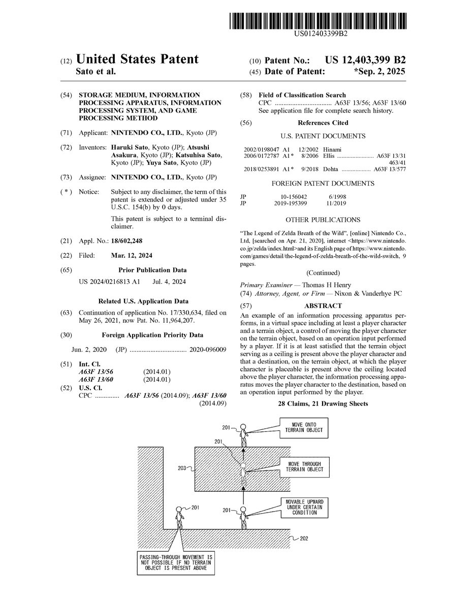
FIG.8is a schematic diagram showing a state where a player character performs passing-through movement in a game space according to the exemplary embodiment.FIG.8shows the game space as seen from a direction parallel to the horizontal direction. In the game state shown inFIG.8, a player character201is placed on a terrain object202, and a terrain object203serving as a ceiling is present above the player character201. In this state, the player character201is allowed to pass through the terrain object203and move onto the terrain object203, on condition that a movement condition described later is satisfied (seeFIG.8).
In this specification, a terrain object is any object which is placed in a game space, and at least a part of which allows a player character to be placed thereon. The terrain object may represent the ground or a building in the game space. Moreover, in the exemplary embodiment, an object (e.g., an object representing a rock, a big box, or the like) placed on the terrain object representing the ground is also a kind of a terrain object. The terrain object may be an object that moves under a predetermined condition, such as a rock object that moves when a certain game condition is satisfied.
In this specification, a ceiling is not limited to a ceiling part of a building object. Apart, of any terrain object, which faces downward and allows passing-through movement can be a ceiling. For example, when a cave is formed by a terrain object representing the ground or a tunnel is formed by a terrain object representing a mountain, a part, of the terrain object, facing downward is a ceiling.
As shown inFIG.8, when the player character performs passing-through movement, it does not mean that a hole is formed through the terrain object. When the passing-through movement according to the exemplary embodiment is performed, collision determination between the player character and the terrain object is exceptionally omitted, whereby the player character is moved while ignoring collision determination with the terrain object.
The passing-through movement is a motion different from a motion of the player character jumping up from the ground. In the exemplary embodiment, the passing-through movement is a motion performed at least on condition that a ceiling is present above the player character. If no ceiling is present above the player character, the player character does not perform the passing-through movement (seeFIG.8). In this case, the player character does not perform even a jump action. Therefore, it can be said that the passing-through movement is a motion different from a common jump action, i.e., a jump of the player character in response to an operation performed by the player. In the exemplary embodiment, the player character is allowed to perform a jump action by an operation different from that for the passing-through movement.
In the exemplary embodiment, the aforementioned passing-through movement allows the player character to move onto the terrain object located above the player character. Therefore, for example, the passing-through movement allows the player character to quickly escape from an underground cave or quickly move onto a roof from the inside of a building. Moreover, for example, when there is a cave beneath a building where the player character cannot enter because the entrance door is locked, the passing-through movement allows the player character to enter the building from the cave. Thus, the passing-through movement offers unprecedented moving methods, thereby enhancing strategic characteristics of the game.
[2-2. Movement Conditions]
Next, conditions for the player character to perform the aforementioned passing-through movement (referred to as “movement conditions”) will be described. In the exemplary embodiment, the movement conditions include a ceiling condition regarding a ceiling and a destination condition regarding a destination. The passing-through movement can be performed when both the ceiling condition and the destination condition are satisfied. Hereinafter, the ceiling condition and the destination condition will be described.
[2-2-1. Ceiling Condition]
In the exemplary embodiment, the ceiling condition is a condition regarding a ceiling above a player character, and includes four conditions as follows:a height condition regarding a height from the player character to the ceiling;a ceiling angle condition regarding an inclination angle of the ceiling;an area condition regarding the area of the ceiling; andan object condition regarding an object provided to the ceiling.
In the exemplary embodiment, if the above four conditions are satisfied, the game system1determines that the ceiling condition is satisfied (i.e., there is a ceiling that allows passing-through movement). If at least one of the four conditions is not satisfied, the game system1determines that the ceiling condition is not satisfied. In another embodiment, the ceiling condition may not necessarily include all the four conditions, and may include at least one of the four conditions. Alternatively, the ceiling condition may include a condition different from the four conditions.
FIG.9shows an example of cases where the height condition is satisfied and where it is not satisfied. In the exemplary embodiment, the height condition is that the distance from the position of the player character201to a ceiling (i.e., the terrain object203serving as the ceiling) is within a predetermined distance. The game system1determines the height condition, based on a distance (referred to as “ceiling distance”) L from the player character201to the ceiling. That is, if the ceiling distance L is within the predetermined distance, the height condition is satisfied (see (a) ofFIG.9). Meanwhile, if the ceiling distance L is longer than the predetermined distance, the height condition is not satisfied (see (b) ofFIG.9).
A method for calculating the ceiling distance L is arbitrary, and the exemplary embodiment adopts the following method, for example. That is, the ceiling distance L is calculated by using straight lines (referred to as “rays”) that are set based on the position of the player character.FIG.10shows an example of rays set around a player character. As shown inFIG.10, the game system1virtually places, in the game space, rays301to306extending upward from a start point a, around the player character201. In the exemplary embodiment, six rays301to306are set. That is, in the exemplary embodiment, it can also be said that a hexagonal column having a player character inside is virtually placed. In another embodiment, the number of rays to be set may be any number not less than 1.
In the exemplary embodiment, the six rays301to306are located at the vertices of a hexagon centering around the position of the player character201as seen from above the game space (seeFIG.10). However, rays may be arranged at any positions around the player character201. The start points a of the respective rays301to306are set at positions near the feet of the player character201(specifically, positions at the lower end of the player character201) with respect to the up-down direction (seeFIG.10). Even when the terrain object on which the player character201is placed has irregularities or a slope, the start points a of the respective rays301to306are set at the same height with respect to the up-down direction. The positions of the start points with respect to the up-down direction may be any positions that depend on the position of the player character201in the up-down direction. In another embodiment, the positions of the start points with respect to the up-down direction may be set at the position of the head of the player character201, for example.
The game system1calculates, for each ray, a length from the start point a of the ray to a position where the ray is in contact with the ceiling (referred to as “contact point”). Then, the game system1calculates a ceiling distance L, based on the lengths from the start points a to the contact points of the respective rays301to306. For example, the ceiling distance L may be calculated as an average value of the lengths from the start points to the contact points of the six rays301to306(however, rays not in contact with the ceiling are excluded). Based on the plurality of rays, the ceiling distance L can be calculated with high accuracy even if the ceiling has irregularities or a slope.
As described above, in the exemplary embodiment, the game system1sets the height condition, and causes the player character to perform passing-through movement, on condition that the distance (e.g., the ceiling distance L) from the player character to the ceiling satisfied the height condition. That is, the game system1causes the player character to perform passing-through movement if it is satisfied that the terrain object serving as the ceiling is present within the predetermined distance upward from the player character. In this case, even when the terrain object is present above the player character, if the terrain object is too far apart from the player character, passing-through movement to the terrain object can be inhibited. For example, it is assumed that a terrain object is present far above the ground, and the terrain object is a place where the player character would reach after the game is progressed. In this case, if passing-through movement to this place is allowed, inconvenience may occur in the progress of the game. However, according to the exemplary embodiment, since the height condition is set, the possibility of such inconvenience can be reduced.
Moreover, as described above, in the exemplary embodiment, it can also be said that determination of the height condition (i.e., determination as to whether or not a terrain object serving as a ceiling is present within the predetermined distance upward from the player character) is performed based on whether or not a virtually placed determination shape, which has a predetermined height and extends upward from the position of the player character, is in contact with the terrain object. The determination shape according to the exemplary embodiment is a shape defined by the six rays301to306, and can be regarded as a hexagonal column in which the six rays301to306correspond to the sides of the side faces thereof. The height of this hexagonal column is equal to the predetermined distance that is a threshold value for the height condition. In another embodiment, the determination shape may be any columnar shape, such as a polygonal column other than a hexagonal column, or a cylindrical shape. As described above, determination of the height condition can be easily performed by using the determination shape. Although described later in detail, the determination shape (specifically, the rays301to306) is also used for determinations regarding the ceiling angle condition, the area condition, and the object condition. Use of the determination shape facilitates the determinations regarding these conditions, as in the case of the height condition.
FIG.11shows an example of cases where the ceiling angle condition is satisfied and where it is not satisfied. In the exemplary embodiment, the ceiling angle condition is that an inclination angle of a ceiling located above the player character201is within a predetermined angle. Specifically, the inclination angle is an inclination angle θ1, with respect to the horizontal direction, of the terrain object203serving as the ceiling (seeFIG.11).
The game system1determines the ceiling angle condition, based on the inclination angle θ1. That is, if the inclination angle θ1is smaller than or equal to a predetermined angle (e.g., 50°), the ceiling angle condition is satisfied (see (a) ofFIG.11). Meanwhile, if the inclination angle θ1is greater than the predetermined angle, the ceiling angle condition is not satisfied (see (b) ofFIG.11). Thus, when the inclination angle θ1is great, the part, of the terrain object203, located above the player character201is regarded as a wall rather than a ceiling, and therefore, passing-through movement is not performed.
A method for calculating the inclination angle θ1is arbitrary, and the exemplary embodiment adopts the following method, for example. That is, in the exemplary embodiment, the inclination angle θ1is calculated by using the aforementioned rays. Specifically, the game system1calculates, for each ray, an inclination angle of the terrain object203at the contact point where the ray is in contact with the ceiling. Then, the game system1calculates the inclination angle θ1as an average value of the inclination angles calculated for the respective rays. According to this method, the inclination angle can be calculated with high accuracy even when the ceiling has irregularities.
As for the ceiling angle condition, the following determination method may be adopted instead of or in addition to the above determination method. Firstly, the game system1calculates the heights of the contact points for the respective rays301to306. Next, the game system1calculates an angle (specifically, an angle with respect to the horizontal direction) of a plane that passes any three contact points. In the exemplary embodiment, the game system1calculates the angle of the plane for each combination of the three contact points, and determines that the ceiling angle condition is not satisfied if the angle of any plane is greater than a reference angle. According to this method, for example, if the ceiling located above the player character201has a step larger than a predetermined reference size, it is determined that the ceiling angle condition is not satisfied (see (c) ofFIG.11). Therefore, if passing-through movement needs to be prevented from being performed when the ceiling has such a step, the game system1may determine the ceiling angle condition by the above method.
As described above, based on the state of the terrain object (e.g., the inclination angle of the ceiling, a step in the ceiling, the placement state of a prohibited object described later, or the like) at a part in contact with the determination shape (e.g., a hexagonal column defined by the six rays301to306), the game system1determines whether or not the part of the terrain object is regarded as a ceiling. Thus, it is possible to reduce the possibility of passing-through movement to be performed at a part having a steep slope that cannot be regarded as a ceiling, or a part having a large step. Moreover, it is possible to reduce the possibility that inconvenience occurs in the progress of the game due to passing-through movement performed in a place where passing-through movement is not intended by a game creator.
FIG.12shows an example of cases where the area condition is satisfied and where it is not satisfied. In the exemplary embodiment, the area condition is that a projection area on a ceiling located above the player character201is larger than or equal to a predetermined quantity. Specifically, when a planar region that intersects the player character201and is parallel to the horizontal direction (specifically, a hexagonal region having, as vertices, the start points of the six rays301to306) is upwardly projected onto the ceiling, the projection area is an area of the region projected onto the ceiling.
The game system1determines the area condition, based on the projection area. That is, if the projection area is larger than or equal to a predetermined quantity (e.g., ⅔ of the area of the hexagonal region), the area condition is satisfied (see (a) ofFIG.12). Meanwhile, if the projection area is smaller than the predetermined quantity, the area condition is not satisfied. For example, as shown in (b) ofFIG.12, if only a part of the planar region is projected onto the ceiling of the terrain object203, the projection area is small and therefore the area condition is not satisfied. Thus, when the projection area is small, the game system1determines that the part, of the terrain object203, located above the player character201is not a ceiling that allows passing-through movement, and does not cause the player character201to perform passing-through movement.
A method for calculating the projection area is arbitrary, and the exemplary embodiment adopts the following method, for example. That is, in the exemplary embodiment, when a hexagonal region formed by line segments connecting the start points of the rays301to306is upwardly projected onto the ceiling, the game system1calculates, as the projection area, an area of the projected region. In another embodiment, the game system1may calculate a rough value of a projection area, based on the number of rays that are in contact with the terrain object203serving as the ceiling among the six rays301to306. At this time, determination of the area condition may be performed based on whether or not the number of rays in contact with the terrain object203is larger than or equal to a predetermined number (e.g., 4).
As described above, in the exemplary embodiment, determination as to whether or not a terrain object serving as a ceiling is present within the predetermined distance upward from the player character, includes determination of the area condition. That is, determination as to whether or not a terrain object serving as a ceiling is present within the predetermined distance upward from the player character, is performed based on the size of a part, of the determination shape, which is in contact with the surface of the terrain object (e.g., based on the projection area). If the player character is allowed to perform passing-through movement even though the projection area is small, there is a possibility of unnatural display such that, when the player character moves while passing through the terrain object, a part of the player character protrudes from the terrain object. In contrast, according to the exemplary embodiment, use of the area condition can reduce the possibility of such unnatural display.
FIG.13shows an example of cases where the object condition is satisfied and where it is not satisfied. In the exemplary embodiment, the object condition is that a prohibited object205is not disposed on the terrain object203serving as a ceiling. Here, the prohibited object205is a specific object defined in the game program, for example, an object with spines (seeFIG.13).
The game system1determines whether or not a prohibited object205is disposed on the ceiling above the player character201. Specifically, the game system1determines the object condition, based on whether or not the rays301to306are in contact with the prohibited object205. That is, if none of the rays301to306are in contact with the prohibited object205, the object condition is satisfied (see (a) ofFIG.13). Meanwhile, if at least any of the rays301to306is in contact with the prohibited object205, the object condition is not satisfied (see (b) ofFIG.13).
A specific method for determining whether or not a prohibited object is disposed on the ceiling above the player character201is arbitrary. For example, in another embodiment, the game system1may determine that the object condition is satisfied if the number of rays in contact with the prohibited object205is less than or equal to a predetermined number (e.g., 1).
When the prohibited object205is not disposed on the surface of the ceiling (i.e., when there is another terrain object between the player character and the prohibited object205above the player character), even if the prohibited object205is present at the leading ends of the rays upwardly extended, the game system1may determine that the object condition is satisfied. For example, in the state where the prohibited object205is disposed on the terrain object serving as the ceiling, if another object is disposed so as to cover the prohibited object205(e.g., if the player character201has moved the another object), the game system may determine that the object condition is satisfied with respect to the another object. Thus, even in a place where a prohibited object is disposed, the player can devise a way to enable the player character201to perform passing-through movement, by using another object. In another embodiment, when there is a prohibited object between the player character201and a destination, the game system1may determine that the object condition is not satisfied.
As described above, based on the state (e.g., the placement state of a prohibited object) of a part, of a terrain object, which is in contact with the determination shape (e.g., a hexagonal column defined by the six rays301to306), the game system1determines whether or not this part of the terrain object is regarded as a ceiling. Thus, the game creator can easily prohibit passing-through movement of the player character, through setting of the state of the terrain object. For example, when there is a place where passing-through movement, if permitted, is likely to cause inconvenience in the progress of the game, the game creator can reduce the possibility of such inconvenience by changing the state of the terrain object in the place (by disposing a prohibited object, for example).
The phrase “the state of a terrain object” may be the state regarding the terrain object itself regardless of whether or not another object is disposed on the terrain object. The phrase “the state of a terrain object” may be, for example, the state regarding whether or not the terrain object itself is a prohibited object.
[2-2-2. Destination Condition]
Next, the destination condition will be described.FIG.14shows an example of cases where the destination condition is satisfied and where it is not satisfied. The destination condition is a condition regarding a destination above the player character, and includes two conditions as follows:a destination angle condition regarding an inclination angle of a place to be a destination; anda space condition regarding a space at the destination.
If both the two conditions are satisfied, the game system1determines that the destination condition is satisfied (i.e., there is a destination where the player character can be placed). If at least one of the two conditions is not satisfied, the game system1determines that the destination condition is not satisfied. In another embodiment, the destination condition may not necessarily include the two conditions, and may include at least one of the two conditions. The destination condition may include a condition different from the two conditions.
The destination angle condition is that an inclination angle of an upward-directed place P, which is located on an upper side of a terrain object203forming a ceiling above the player character201, is within a predetermined angle. Specifically, this inclination angle is an inclination angle θ2, with respect to the horizontal direction, of the place P in the terrain object203(seeFIG.14). A method for calculating the inclination angle θ2is arbitrary, and the inclination angle θ2may be calculated by using the rays as in the case of the inclination angle θ1.
The game system1determines the destination angle condition, based on the inclination angle θ2. That is, if the inclination angle θ2is smaller than or equal to a predetermined angle (e.g., 50°), the destination angle condition is satisfied (see (a) ofFIG.14). Meanwhile, if the inclination angle θ2is greater than the predetermined angle, the ceiling angle condition is not satisfied (see (b1) ofFIG.14). Thus, when the inclination angle θ2is great, the place P is not regarded as a destination where the player character201can be placed, and passing-through movement is not performed.
In the exemplary embodiment, in the state where the player character201is placed on a terrain object, if the inclination angle of the terrain object at the position where the player character201is placed is greater than or equal to a reference angle, the game system1control the player character201to move downward (e.g., to slip down) along the slope, while there is no operation performed by the player. The predetermined angle to be a threshold for the destination angle condition may be the same angle as the reference angle.
The space condition is that a space on the upper side of the place P (i.e., a space outside the terrain object) has a size (specifically, a width, a depth, and a height) that allows placement of the player character201therein. That is, if the space has a predetermined size enough to accommodate the player character201, the space condition is satisfied (see (a) ofFIG.14). Meanwhile, if the space does not have the predetermined size, the space condition is not satisfied (see (b2) ofFIG.14). Thus, when the space is small, the place P is not regarded as a destination where the player character201can be placed, and passing-through movement is not performed.
The predetermined size is at least a size enough to avoid the player character201and the terrain object203from being in contact or overlapped with one another at somewhere other than the place P if the player character201is placed in the place P.
As described above, in the exemplary embodiment, when the determination condition based on at least one of: the state (e.g., the inclination angle θ2) of the upward-directed place in the terrain object and above the player character; and the size of the space outside the terrain object and on the upper side of the place, is further satisfied, the game system1performs control of passing-through movement with the place being a destination. Thus, it is possible to reduce the possibility that the player character is moved by passing-through movement to a place where the player character cannot be placed.
The phrase “the state of the upward-directed place in the terrain object” includes not only the state related to the inclination angle in the place but also the type of the terrain object in the place, or the state related to the space on the upper side of the place. For example, in another embodiment, when the place in the terrain object is an object (e.g., an object representing lava) that will damage the player character on the object, the game system1may determine that the destination condition is not satisfied. Meanwhile, for example, when the space on the upper side of the place in the terrain object is a space (e.g., under water) where the player character can stay only for a certain period of time, the game system1may determine that the destination condition is not satisfied. Thus, the game system1may not regard, as a destination, a place where the player character cannot be placed, and moreover, may exclude a specific place from destinations even though the player character can be placed on the place.
In the game space, a plurality of terrain objects may be placed in layers. In this case, a plurality of layers of terrain objects may be present above the player character. Hereinafter, a destination determining method in the case where a plurality of layers of terrain objects are present above the player character, will be described.
FIG.15shows an example of a case where a plurality of terrain objects are present above the player character. In the example shown inFIG.15, two terrain objects203and207are present above the player character201. In addition, an upward-directed place P1in the terrain object203located above the player character201and serving as a ceiling does not satisfy the destination condition, while an upward-directed place P2in the terrain object207located above the terrain object203satisfies the destination condition.
In the example shown inFIG.15, firstly, the game system1determines whether or not the destination condition is satisfied with respect to the terrain object203closest to the player character201among the terrain objects located above the player character201. If the destination condition is not satisfied with respect to the terrain object203, the game system1determines whether or not the destination condition is satisfied with respect to the terrain object207closest to the player character201, except the terrain object203, among the terrain objects located above the player character201. In the example shown inFIG.15, since the place P2in the terrain object207satisfies the destination condition, the place P2is determined as a destination (seeFIG.15).
As described above, when a plurality of terrain objects are present above the player character201, the game system1determines whether or not the destination condition is satisfied with respect to these terrain objects in order from one closest to the player character201. The game system1repeats the determination until there is a terrain object for which the destination condition is satisfied. If the destination condition is not satisfied with respect to any of the terrain objects, the game system1determines that the movement condition is not satisfied, and does not cause the player character201to perform passing-through movement. Meanwhile, if there is a terrain object for which the destination condition is satisfied, the game system1causes the player character201to perform passing-through movement to the destination terrain object. Thus, in the exemplary embodiment, a destination can be determined even when there are a plurality of terrain objects above the player character201.
[2-3. Flow of Game Operation and Game Display Related to Passing-Through Movement]
In the exemplary embodiment, the aforementioned passing-through movement is performed by the player character201using a predetermined movement item. Specifically, during the game, the player firstly performs an item designating instruction to make the player character201able to use the movement item. In this state, the player can cause the player character201to perform passing-through movement by performing a movement start instruction (on condition that the movement condition is satisfied). Hereinafter, an operation of the player for causing the player character201to perform passing-through movement and display in the case where the passing-through movement is performed, will be described.
[2-3-1. Game Image Before Passing-Through Movement]
FIG.16shows an example of a game image in the state before a movement item becomes usable. As shown inFIG.16, in this state, a game image showing a game space including a player character201is displayed on the display12. That is, the game system1sets a virtual camera for creating the game image at a position and an orientation such that the player character201is included in the field of view of the virtual camera. In this state, the player can perform an operation of moving the player character201on a terrain object211representing the ground, and can perform an item designating instruction for making the player character201able to use the movement item.
In the above state, when the player performs an item designating instruction, the player character201becomes able to use the movement item. A specific operation method for performing the item designating instruction is arbitrary. For example, the game system1may receive, as an item designating instruction, an operation of changing, to the movement item, an item to be made usable from among a plurality of items possessed by the player character201.
In the exemplary embodiment, in response to the item designating instruction having been performed, the game system1changes the position and orientation of the virtual camera so as to be directed upward from the position of the player character201.FIG.17shows an example of a game image displayed in response to the item designating instruction having been performed in the state shown inFIG.16. In the state shown inFIG.16, a terrain object212serving as a ceiling is present above the player character201. Therefore, when the virtual camera is directed upward in response to the item designating instruction having been performed, the terrain object212serving as the ceiling is displayed on the display12as shown inFIG.17. In the example shown inFIG.17, the player character201is not displayed. In another embodiment, a part (e.g., head) of the player character201may be displayed when the virtual camera is directed upward. The virtual camera may not necessarily be directed straight upward, and may be oriented such that the ceiling located above the player character201is included in the field of view.
The position and orientation of the virtual camera are automatically changed in response to the item designating instruction (that is, without an instruction by the player other than the item designating instruction). Thus, after performing the item designating instruction, the player can easily confirm whether or not there is a ceiling above the player character201.
In the exemplary embodiment, in the state where the virtual camera is directed upward in response to the item designating instruction having been performed, the game system1receives, from the player, an operation of changing the orientation of the virtual camera. Therefore, in the above state, the player can change the line-of-sight direction of the virtual camera to any direction. In another embodiment, the virtual camera may not necessarily be directed upward automatically in response to an item designating instruction. The player may operate the virtual camera so as to be directed upward according to need.
In the exemplary embodiment, when the terrain object serving as the ceiling is displayed in response to the item designating instruction, the game system1displays a mark310representing a determination result regarding the movement condition (seeFIG.17). In the exemplary embodiment, the mark310is displayed on the terrain object212serving as the ceiling. Specifically, the mark310is displayed at a position above the player character201, i.e., at a position where the determination shape is in contact with the terrain object212. The mark310may not necessarily be placed on the surface of the terrain object212, and may be placed near the surface of the terrain object212(e.g., at a position a little apart from the surface).
If the item designating instruction is performed in the state where the terrain object serving as the ceiling is not present within a predetermined distance upward from the player character201(i.e., in the state where the height condition is not satisfied), the mark310is placed at a predetermined position above the player character201. This predetermined position is, for example, a position the predetermined distance apart from the player character201.
The mark310is displayed in different display modes between the case where the movement condition is satisfied and the case where it is not satisfied. In the exemplary embodiment, the color of the mark310differs between the former case and the latter case (see (a) and (b) ofFIG.17). InFIG.17, the difference in the color of the mark310is indicated by presence/absence of hatching.
As described above, in the exemplary embodiment, display representing the determination result regarding the movement condition is performed by rendering a part (e.g., the mark310) in which the terrain object is in contact with the determination shape, in different display modes according to the determination result. This allows the player to easily confirm whether or not the destination condition is satisfied (i.e., whether or not passing-through movement is possible). The phrase “rendering the part in different display modes according to the determination result” includes the meaning that a mark is displayed at the part as for one determination result while no mark is displayed at the part as for the other determination result.
In the exemplary embodiment, a display (specifically, the mark310) representing the determination result regarding the movement condition is placed on the terrain object serving as the ceiling. Here, the position of the display representing the determination result regarding the movement condition is arbitrary. For example, in another embodiment, the position of the display representing the determination result regarding the movement condition may be the position where the determination shape is placed. For example, in a modification of the exemplary embodiment, the rays301to306may be displayed in different display modes according to the determination result. Thus, in the exemplary embodiment or the modification, the display representing the determination result regarding the movement condition is performed in at least one of: the part where the terrain object is in contact with the determination shape; and the position where the determination shape is placed. Thus, the position of the ceiling to be subjected to determination regarding the movement condition is displayed in association with the result of the determination, whereby both of them can be presented in an easy-to-understand manner for the player.
In another embodiment, in the state where the movement item is usable (e.g., the state where the game image shown inFIG.17is displayed), the game system1may receive an operation for causing the player character201to move on the terrain object211. Thus, by causing the player character201to move, the player can easily search for the position of the player character201where passing-through movement is possible.
[2-3-2. Creation of Game Image at Passing-Through Movement]
In the state where the movement item is usable, the game system1receives a movement start instruction of starting passing-through movement by using the movement item, and a cancellation instruction of canceling this state. When the movement start instruction has been performed by the player, the game system1starts a motion control process of causing the player character201to perform passing-through movement (i.e., a passing-through movement process in step S13shown inFIG.20), on condition that the movement condition is satisfied. Meanwhile, when the cancellation instruction has been performed by the player, the game system1returns the position and orientation of the virtual camera to those before the item designating instruction. Thus, the game image showing the game space including the player character201as shown inFIG.16is displayed on the display12.
In the motion control process of causing the player character201to perform passing-through movement, firstly, the game system1moves the player character201upward. When the passing-through movement is performed, the game system1may display a columnar effect image extending upward from the position of the player character201, and may control the player character201so as to move upward inside the columnar effect image. The effect image may be translucently displayed so that the player character201located inside is visible. With the effect image, the path in which the player character201moves can be presented in an easy-to-understand manner for the player. The effect image may be displayed only when the player character201is located outside the terrain object, or may be displayed in both cases where the player character201is located outside the terrain object and where it is located inside the terrain object.
While the player character201is moved upward, the player character201comes into contact with the terrain object212serving as the ceiling. In the motion control process, the upward movement of the player character201is continued even after the contact, and as a result, the player character201moves upward inside the terrain object212. In a normal process (i.e., a process other than the motion control process), a collision determination process is performed between the player character201and the terrain object212, so that the player character201does not enter the terrain object212.
FIG.18shows an example of placement of a player character and a virtual camera in the case where the player character moves inside a terrain object. In the exemplary embodiment, during the passing-through movement, the game system1places a virtual camera311at a position and an orientation that allow the player character201to be included in the field of view of the virtual camera311. For example, the virtual camera311is placed at the same position as the player character201with respect to the up-down direction and is directed in the horizontal direction (seeFIG.18). At this time, the virtual camera311is placed at a position a predetermined distance apart from the player character201. Since the player character201moves upward during the passing-through movement, the virtual camera311also moves upward with the movement of the player character201.
During the passing-through movement, the virtual camera311may be placed inside the terrain object212(see (a) ofFIG.18). In this case, the game system1places a background object312behind the player character201as seen from the virtual camera311. In the exemplary embodiment, the background object312has a size that can cover the field of view of the virtual camera311, and is placed at a position so as to cover the field of view of the virtual camera311(i.e., so that the terrain object212behind the background object312is not displayed) (see (a) ofFIG.18). Therefore, in this case, the player character201and the background object312behind the player character201are displayed on the display12while the terrain object212(strictly speaking, a polygon on the surface of the terrain object212) is not displayed. A texture rendered on the background object312is arbitrary. For example, an image representing a scene in which the player character201moves underground or an image representing a scene in which the player character201moves by space warp, is rendered on the background object312.
As described above, in the exemplary embodiment, during the passing-through movement, the background object is displayed if the virtual camera311is placed inside the terrain object. Thus, it is possible to avoid inconvenience that may occur if the display process is performed from a viewpoint on the back side (in other words, from the inside) of the polygon on the terrain object212. For example, the back side of the polygon is not rendered in many cases, which may cause a problem that the terrain object212is partially displayed or is not displayed and thereby the appearance thereof is deformed. Even if the back side of the polygon is rendered, the appearance is still unnatural because the back side of an object is usually not displayed. In contrast, use of the background object312can reduce unnaturalness of the appearance.
On the other hand, during the passing-through movement, if the virtual camera311is placed outside the terrain object212, the background object312is not placed (see (b) ofFIG.18). In this case, a game image showing a game space in which the terrain object212is viewed from the outside (e.g., a game image showing the side wall of the terrain object212) is displayed. In this case, the player character201is not displayed. However, in another embodiment, in the above case, the game system1may display the player character201inside the terrain object212so as to be translucent and overlapped with the terrain object212, or may display the terrain object212so as to be translucent so that the player character201can be seen through. In another embodiment, even if the virtual camera311is placed outside the terrain object212, the background object312may be placed as in the case where the virtual camera311is placed inside the terrain object212. At this time, the game system1does not display the surface of the terrain object212(specifically, the polygon on the terrain object212) located between the virtual camera311and the player character201.
The content of the game image representing the player character201passing through the terrain object during the passing-through movement is arbitrary. In another embodiment, the game image may be created and displayed by a method different from that for the exemplary embodiment.
As described above, in the exemplary embodiment, the game system1moves the player character201upward from the current position, and further moves the player character201so as to pass through the terrain object from the ceiling, thereby moving the player character201to the destination. This allows the player to intuitively recognize that the player character201passes through the terrain object when moving from the current position to the destination on the upper side of the terrain object.
In another embodiment, when moving the player character201to the destination by the passing-through movement, the game system1may not necessarily display an animation showing the player character201passing through the terrain object. For example, the game system1may display an animation showing the player character201moving by space warp to the destination from the position before the movement.
In the exemplary embodiment, when moving the player character201to the destination by the passing-through movement, the game system1displays different animations between the case where the player character201moves inside the terrain object and the case where the player character201moves outside the terrain object. For example, when the player character201moves inside the terrain object, the game system1displays an animation including the background object or an animation showing the side wall of the terrain object. This allows the player to easily recognize that the player character201moves inside the terrain object.
In the exemplary embodiment, as an animation showing movement of the player character201in the case where the player character201is moved to the destination by the passing-through movement, the game system1creates an animation different from an animation showing the player character201moving on the terrain object (e.g., an animation showing the player character201walking or running on the terrain object). For example, the game system1causes the player character201during the passing-through movement to take a posture of jumping up or a posture of swimming upward. This allows the player to easily recognize that movement (i.e., passing-through movement) different from the normal movement of the player character201on the terrain object is performed.
If the distance from the movement start position to the destination in the passing-through movement is longer than a predetermined reference distance, the game system1may increase the moving speed of the player character201. Thus, the time required for the passing-through movement can be reduced if the time seems to be long.
When the player character201has arrived at the destination by the passing-through movement, the game system1ends the motion control process of causing the player character201to perform passing-through movement. In the exemplary embodiment, when the passing-through movement has ended, the state in which the player character201can use the movement item is canceled automatically (i.e., without an operation of the player). Thus, the player can perform a movement operation or the like on the player character201without performing the aforementioned cancellation instruction. In another embodiment, when the passing-through movement has ended, the game system1may maintain the state where the player character201can use the movement item.
In the exemplary embodiment, while the passing-through movement is performed, the game system1does not receive an operation of the player on the player character201. Thus, the player character201is prevented from being moved to a position different from the destination specified when the item designating instruction was performed. In another embodiment, the game system1may receive an operation of the player on the player character201even while the passing-through movement is performed. Alternatively, the game system1may receive an operation (e.g., an operation of causing the player character to use another item) other than the operation of moving the player character201while the passing-through movement is performed.
As described above, in the exemplary embodiment, according to a first instruction (e.g., item designating instruction) by an operation input performed by the player, the game system1performs: determination as to whether or not a determination condition (e.g., movement condition) that a terrain object serving as a ceiling is present within a predetermined distance upward from a player character and that a destination located on the terrain object is present above the ceiling located above the player character, is satisfied; and display of a result of the determination (e.g., display of the mark310). Then, if the determination condition is satisfied, the game system1moves the player character to the destination, in response to a second instruction (e.g., movement start instruction) by an operation input performed by the player. Thus, the player can perform the second instruction of actually starting passing-through movement after confirming whether or not the passing-through movement is possible. Therefore, it is possible to reduce the possibility that the player performs the second instruction when the passing-through movement is not possible, thereby enhancing operability for the passing-through movement.
In the exemplary embodiment, the player character performs the passing-through movement by using the movement item. In another embodiment, use of a specific item such as the movement item may not necessarily be a condition for the passing-through movement. That is, in the another embodiment, the player character may be able to perform the passing-through movement regardless of whether or not the player character has the specific item.
3. Specific Example of Processing in Game System
Next, a specific example of information processing in the game system1will be described with reference toFIGS.19to21.
FIG.19shows an example of various data to be used for the information processing in the game system1. The various data shown inFIG.19are stored in a storage medium (e.g., the flash memory84, the DRAM85, and/or a memory card attached to the slot23) that is accessible by the main body apparatus2.
The game system1stores therein a game program as shown inFIG.19. The game program is a game program for executing a game (specifically, a game control process shown inFIG.20) according to the exemplary embodiment. The game system1stores therein operation data, camera data, character data, destination candidate data, and destination data.
The operation data is transmitted from the controllers3and4to the main body apparatus2and stored in the main body apparatus2as described above. In the exemplary embodiment, the operation data includes input data indicating inputs to the respective input sections described above. The camera data indicates information regarding a virtual camera set in a virtual game space (e.g., information indicating the position, the orientation, etc., of the virtual camera). The character data indicates information regarding a player character placed in the game space (e.g., the position, the orientation, the state, etc., of the player character). The destination candidate data indicates candidates for a destination in the game space, specifically, the positions (e.g., coordinates) of the candidates. The destination data indicates a destination in the game space, specifically, the position (e.g., coordinates) of the destination.
FIG.20is a flowchart showing an example of a flow of a game control process executed by the game system1. The game control process shown inFIG.20is started in response to that the player character201is placed in the game space during execution of the game program. Although not shown inFIG.20, the game control process is ended when a menu screen is displayed by an instruction of the user or when the game is ended by an instruction of the user.
In the exemplary embodiment, the processor81of the main body apparatus2executes the game program stored in the game system1, thereby executing processes in steps shown inFIG.20. However, in another embodiment, a part of the processes in the steps may be executed by a processor (e.g., a dedicated circuit or the like) other than the processor81. If the game system1is communicable with another information processing apparatus (e.g., a server), a part of the processes in the steps shown inFIGS.20and21may be executed by the information processing apparatus. The processes in the steps shown inFIGS.20and21are merely examples, and the processing order of the steps may be changed or other processes may be executed in addition to (or instead of) the processes in the steps, so long as similar results can be obtained.
The processor81executes the processes in the steps shown inFIGS.20and21by using a memory (e.g., the DRAM85). That is, the processor81stores, in the memory, information (in other words, data) obtained in each process step, and reads out the information from the memory when using the information in the subsequent process steps.
In step S1shown inFIG.20, the processor81determines whether or not an item designating instruction as described above has been performed by the player. In the exemplary embodiment, the processor81determines whether or not various instructions (e.g., an item designating instruction, a cancellation instruction, and a movement start instruction) have been performed by the player, based on the operation data acquired from the controller3or4. Here, the processor81acquires, at appropriate timing, the operation data received from each controller via the controller communication section83and/or the terminals17and21, and stores the operation data in the memory. The processor81performs the aforementioned determination, based on the acquired operation data. When the determination result in step S1is negative, the process in step S2is executed. When the determination result in step S1is positive, the process in step S3is executed.
In step S2, the processor81executes a control process of causing a player character to move on a terrain object. For example, the processor81causes the player character to perform a motion of moving (e.g., a motion of walking or running) on the terrain object, in response to a direction input to the controller (e.g., a direction input to the analog stick32). At this time, the processor81updates the character data stored in the memory so as to indicate the content of the motion of the player character after the control. Moreover, in step S2, the processor81creates a game image showing a game space after the control process, and displays the game image on the display12. The process in step S2may be the same as the conventional game control process. The game system1may execute a process of controlling movements of other objects such as a virtual camera, an enemy object, etc., in addition to executing the process of controlling the movement of the player character. Next to step S2, the process in step S1is executed again.
A process loop of steps S1and S2is executed once every predetermined time (e.g., every frame time). That is, in the exemplary embodiment, the processor81determines whether or not an item designating instruction has been performed, once every predetermined time.
In step S3, the processor81sets the position and orientation of the virtual camera so that the virtual cameral is directed upward from the position of the player character. Specifically, the processor81updates the camera data stored in the memory so that the content of the camera data indicates the set position and orientation. The process in step S3causes a game image showing a ceiling above the player character (seeFIG.17) to be displayed in step S7or S10described later. Next to step S3, the process in step S4is executed.
In step S4, the processor81determines whether or not the aforementioned ceiling condition is satisfied with respect to the current position of the player character. This determination is performed according to the method described in the above “[2-2-1. Ceiling condition]”. When the determination result in step S4is positive, the process in step S5is executed. When the determination result in step S4is negative, the process in step S7described later is executed.
In step S5, the processor81determines whether or not there is a destination candidate. Here, the destination candidate is a place located closest to the player character among upward-directed places in terrain objects serving as ceilings located above the player character, excluding a place determined not to satisfy the destination condition in step S6described later. When there is such a place, the processor81sets this place as a destination candidate. That is, the processor81stores, in the memory, data indicating the position of the place as destination candidate data. When the determination result in step S5is positive, the process in step S6is executed. When the determination result in step S5is negative, the process in step S7described later is executed.
In step S6, the processor81determines whether or not the destination candidate set in step S5satisfies the aforementioned destination condition. This determination is performed according to the method described in the above “[2-2-2. Destination condition]”. When the determination result in step S6is positive, the process in step S7is executed. When the determination result in step S6is negative, the process in step S5is executed again. Therefore, in the exemplary embodiment, a process loop of steps S5and S6is repeated until it is determined that a destination candidate satisfies the destination condition or until it is determined that none of destination candidates satisfy the destination condition.
In step S7, the processor81displays, on the display12, a game image in a display mode indicating that passing-through movement is not possible. At this time, the processor81creates the game image, based on the virtual camera set through the process in step S3. Specifically, the processor81creates the game image showing a game space as seen in a direction according to the orientation of the virtual camera from the position of the virtual camera. At this time, the processor81includes, in the game image, a mark in a display mode indicating passing-through movement is not possible (see (b) ofFIG.17). The game image created as described above is displayed on the display12. Next to step S7, the process in step S8is executed.
In step S8, the processor81determines whether or not a cancellation instruction as described above has been performed by the player. When the determination result in step S8is positive, the process in step S1is executed again. When the determination result in step S8is negative, the process in step S8is executed again. That is, in the exemplary embodiment, after the game image has been displayed in step S7, the processor81waits until the cancellation instruction is performed, and executes the process in step S1again when the cancellation instruction is performed.
Meanwhile, in step S9, the processor81determines, as a destination of passing-through movement, a destination candidate that has been determined to satisfy the destination condition. That is, the processor81updates the content of the destination data stored in the memory to the content stored as the destination candidate data. Next to step S9, the process in step S10is executed.
In step S10, the processor81displays, on the display12, a game image in a display mode indicating that passing-through movement is possible. At this time, the processor81creates the game image, based on the virtual camera as in the process in step S7. Moreover, in step S10, the processor81includes, in the game image, a mark in a display mode indicating that passing-through movement is possible (see (a) ofFIG.17). The game image created as described above is displayed on the display12. Next to step S10, the process in step S11is executed.
In step S11, the processor81determines whether or not a cancellation instruction as described above has been performed by the player. When the determination result in step S11is positive, the process in step S1is executed again. That is, in this case, passing-through movement of the player character is not performed, and the state of the game is returned to the state before the item designating instruction. Meanwhile, when the determination result in step S11is negative, the process in step S12is executed.
In step S12, the processor81determines whether or not a movement start instruction as described above has been performed by the player. When the determination result in step S12is positive, the process in step S13is executed. When the determination result in step S12is negative, the process in step S11is executed again. That is, after the process in step S10, the processor81waits until a cancellation instruction or a movement start instruction is performed.
In step S13, the processor81executes a passing-through movement process. The passing-through movement process is a motion control process of causing the player character to perform a motion for passing-through movement. The passing-through movement process will be described later in detail. When the passing-through movement process has ended, the process in step S1is executed again.
FIG.21is a sub-flowchart showing an example of a specific flow of the passing-through movement process in step S13shown inFIG.20. In the passing-through movement process, firstly in step S21, the processor81moves the player character upward. Specifically, the processor81updates the character data stored in the memory so that the character data indicate a position to which the player character is moved upward from the current position. In the passing-through movement process of the exemplary embodiment, a process loop including a series of processes in steps S21to S26is repeatedly executed once every predetermined time (e.g., every frame time). Therefore, in the process of each step S21, the player character is moved by an amount of movement within the predetermined time. Next to step S21, the process in step S22is executed.
In step S22, the processor81places the virtual camera in accordance with the position of the player character. Specifically, the processor81places the virtual camera at a position and an orientation that allow the player character to be included in the field of view of the virtual camera, based on the position of the player character having been moved in the process of step S21. At this time, the processor81updates the camera data stored in the memory so that the camera data indicates the position after the placement described above. In the exemplary embodiment, since the player character is moved upward by the process in step S21, the virtual camera is also moved upward with the player character. Next to step S22, the process in step S23is executed.
In step S23, the processor81determines whether or not the position of the virtual camera placed by the process in step S22is a position inside the terrain object. This determination is performed based on the camera data stored in the memory and on data that is created based on the game program and indicates the configuration of the game space (this data includes data indicating the position of the terrain object). When the determination result in step S23is positive, the process in step S24is executed. When the determination result in step S23is negative, the process in step S24is skipped and the process in step S25is executed.
In step S24, the processor81places a background object behind the player character as seen from the virtual camera (see (a) ofFIG.18). Specifically, the processor81places the background object in the terrain object according to the method described in the above “[2-3-2. Creation of game image at passing-through movement]”. Next to step S24, the process in step S25is executed.
In step S25, the processor81displays, on the display12, a game image showing the player character performing passing-through movement. As described above, the process loop including the series of processes in steps S21to S26is repeatedly executed once every predetermined time (e.g., every frame time), and therefore, the process in step S25is also executed once every predetermined time. Therefore, the process loop being repeatedly executed causes an animation in which the player character performs passing-through movement to be displayed. Next to step S25, the process in step S26is executed.
In step S26, the processor81determines whether or not the player character has arrived at the destination. This determination can be performed based on the position of the player character indicated by the character data stored in the memory and on the position indicated by the destination data. When the determination result in step S26is positive, the processor81ends the passing-through movement process. When the determination result in step S26is negative, the process in step S21is executed again. Thereafter, the process loop of steps S21to S26is repeatedly executed until it is determined that the player character has arrived at the destination.
4. Function and Effect of Exemplary Embodiment, and Modifications
As described above, in the above exemplary embodiment, the game program causes a computer (e.g., the processor81) of an information processing apparatus (e.g., the main body apparatus2) to execute processes as follows:a normal movement control including at least a control of, in a virtual space including at least a player character and a terrain object, moving the player character on the terrain object, based on an operation input performed by a player; anda special movement control of moving the player character to a destination, based on an operation input (e.g., a movement start instruction) performed by the player, if it is at least satisfied that a terrain object serving as a ceiling is present above the player character and that the destination, on the terrain object, at which the player character is placeable is present above the ceiling located above the player character.
In the above configuration, if the terrain object is present above the player character, the player character can be moved to an upper side of the terrain object, based on the operation input performed by the player. Thus, according to the exemplary embodiment, it is possible to provide a novel method for moving the player character in the game space.
(Modifications Related to Movement Condition)
In the above exemplary embodiment, a condition regarding a distance (specifically, a height) from the current position of the player character is not set with respect to a destination. In another embodiment, the game system1may set, with respect to a destination, a condition regarding the distance from the position of the player character. Specifically, the destination condition may include a height condition that “a distance from the position of a player character to a destination is within a predetermined distance”. The predetermined distance is set to a value greater than a threshold value of the height condition included in the ceiling condition. Thus, it is possible to reduce the possibility that the player character is moved to a place far above the current position by passing-through movement.
In another embodiment, the height condition regarding the height from the player character to the ceiling may not necessarily be set as the ceiling condition included in the movement condition. That is, if there is no place to be excluded, such as the place far above, in the game, a height limit need not be set. Alternatively, the height limit in the height condition may be set to an infinite or sufficient height, which means that there is substantially no height limit.
(Modifications Related to Display when Passing-Through Movement is Performed)
In another embodiment, the game system1may display a game image showing the game space around the destination before the player performs the movement start instruction. This allows the player to confirm the state of the destination before causing the player character to perform passing-through movement. For example, in the state where the game image showing the ceiling (seeFIG.17) is displayed according to the item designating instruction, the game system1may receive, from the player, an instruction of displaying the game image of the destination. When this instruction has been performed, the game system1may display the game image of the destination, on the condition that the movement condition is satisfied.
In another embodiment, the information processing system may not necessarily include a part of the components included in the exemplary embodiment, and may not necessarily perform a part of the processes performed in the exemplary embodiment. For example, in order to achieve a certain specific effect of the exemplary embodiment, the information processing system may include a component for producing the effect and perform a process for producing the effect, in other words, the information processing system may not necessarily include the other components and perform the other processes.
The exemplary embodiment is usable as, for example, a game program and a game system for the purpose of, when a terrain object is present above a player character, moving the player character to an upper side of the terrain object.
While certain example systems, methods, devices and apparatuses have been described herein, it is to be understood that the appended claims are not to be limited to the systems, methods, devices and apparatuses disclosed, but on the contrary, are intended to cover various modifications and equivalent arrangements included within the spirit and scope of the appended claims.
Claims
- A non-transitory computer-readable storage medium having stored therein a game program executable by a processor of an information processing apparatus, wherein the game program, when executed by the processor, causes the information processing apparatus to provide execution comprising: moving a player character, on a terrain object in a virtual space, based on a first operation input;moving the player character, so as to pass through the terrain object in the virtual space, based on a second operation input;and in association with the player character moving within the terrain object in the virtual space and a virtual camera being placed inside the terrain object, placing and rendering a background object in the virtual space.
- The non-transitory computer-readable storage medium according to claim 1, wherein the player character is moved so as to pass through a ceiling part of the terrain object.
- The non-transitory computer-readable storage medium according to claim 1, wherein the player character is moved so as to pass through the terrain object based on satisfying a movement condition.
- The non-transitory computer-readable storage medium according to claim 1, wherein a first animation is displayed in association with the player character moving inside the terrain object, and a second animation, different from the first animation, is displayed in association with the player character moving outside the terrain object.
- The non-transitory computer-readable storage medium according to claim 1, wherein the background object is not placed in the virtual space when the virtual camera is not inside the terrain object.
- The non-transitory computer-readable storage medium according to claim 1, wherein the background object is placed behind the player character as seen from the virtual camera.
- The non-transitory computer-readable storage medium according to claim 1, wherein the background object is of a size covering a field of view of the virtual camera, and the background object is placed at a position so as to cover the field of view of the virtual camera.
- An information processing apparatus, comprising: an input portion;and processing circuitry including at least one processor, wherein the processing circuitry is configured to: move a player character, on a terrain object in a virtual space, based on a first operation input from the input portion;move the player character, so as to pass through the terrain object in the virtual space, based on a second operation input from the input portion;and in association with the player character moving within the terrain object in the virtual space and a virtual camera being placed inside the terrain object, place and render a background object in the virtual space.
- The information processing apparatus according to claim 8, wherein the player character is moved so as to pass through a ceiling part of the terrain object.
- The information processing apparatus according to claim 8, wherein the player character is moved so as to pass through the terrain object based on satisfying a movement condition.
- The information processing apparatus according to claim 8, wherein a first animation is displayed in association with the player character moving inside the terrain object, and a second animation, different from the first animation, is displayed in association with the player character moving outside the terrain object.
- The information processing apparatus according to claim 8, wherein the background object is not placed in the virtual space when the virtual camera is not inside the terrain object.
- The information processing apparatus according to claim 8, wherein the background object is placed behind the player character as seen from the virtual camera.
- The information processing apparatus according to claim 8, wherein the background object is of a size covering a field of view of the virtual camera, and the background object is placed at a position so as to cover the field of view of the virtual camera.
- An information processing system, comprising: a processor;and a memory configured to store computer readable instructions that, when executed by the processor, cause the information processing system to: move a player character, on a terrain object in a virtual space, based on a first operation input;move the player character, so as to pass through the terrain object in the virtual space, based on a second operation input;and in association with the player character moving within the terrain object in the virtual space and a virtual camera being placed inside the terrain object, place and render a background object in the virtual space.
- The information processing system according to claim 15, wherein the player character is moved so as to pass through a ceiling part of the terrain object.
- The information processing system according to claim 15, wherein the player character is moved so as to pass through the terrain object based on satisfying a movement condition.
- The information processing system according to claim 15, wherein a first animation is displayed in association with the player character moving inside the terrain object, and a second animation, different from the first animation, is displayed in association with the player character moving outside the terrain object.
- The information processing system according to claim 15, wherein the background object is not placed in the virtual space when the virtual camera is not inside the terrain object.
- The information processing system according to claim 15, wherein the background object is placed behind the player character as seen from the virtual camera.
- The information processing system according to claim 15, wherein the background object is of a size covering a field of view of the virtual camera, and the background object is placed at a position so as to cover the field of view of the virtual camera.
- A game processing method executed by an information processing system, the method comprising: moving a player character, on a terrain object in a virtual space, based on a first operation input;moving the player character, so as to pass through the terrain object in the virtual space, based on a second operation input;and in association with the player character moving within the terrain object in the virtual space and a virtual camera being placed inside the terrain object, placing and rendering a background object in the virtual space.
- The game processing method according to claim 22, wherein the player character is moved so as to pass through a ceiling part of the terrain object.
- The game processing method according to claim 22, wherein the player character is moved so as to pass through the terrain object based on satisfying a movement condition.
- The game processing method according to claim 22, wherein a first animation is displayed in association with the player character moving inside the terrain object, and a second animation, different from the first animation, is displayed in association with the player character moving outside the terrain object.
- The game processing method according to claim 22, wherein the background object is not placed in the virtual space when the virtual camera is not inside the terrain object.
- The game processing method according to claim 22, wherein the background object is placed behind the player character as seen from the virtual camera.
- The game processing method according to claim 22, wherein the background object is of a size covering a field of view of the virtual camera, and the background object is placed at a position so as to cover the field of view of the virtual camera.
Disclaimer: Data collected from the USPTO and may be malformed, incomplete, and/or otherwise inaccurate.