U.S. Pat. No. 12,390,736
NON-TRANSITORY COMPUTER-READABLE STORAGE MEDIUM HAVING GAME PROGRAM STORED THEREIN, GAME PROCESSING SYSTEM, GAME PROCESSING APPARATUS, AND GAME PROCESSING METHOD
AssigneeNintendo Co., Ltd.
Issue DateSeptember 6, 2023
Illustrative Figure
Abstract
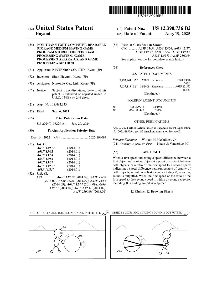
When a first speed indicating a speed difference between a first object and another object at a point of contact between both objects, or a ratio of the first speed to a second speed indicating a speed difference between centers of gravity of both objects, is within a first range including 0, a rolling sound is outputted. When the first speed or the ratio of the first speed to the second speed is within a second range not including 0, a sliding sound is outputted.
Description
DETAILED DESCRIPTION OF NON-LIMITING EXAMPLE EMBODIMENTS Hereinafter, an exemplary embodiment will be described. [Hardware Configuration of Information Processing System] Hereinafter, an information processing system (game system) according to an example of the exemplary embodiment will be described below. An example of a game system1according to the exemplary embodiment includes a main body apparatus (an information processing apparatus, which functions as a game apparatus main body in the exemplary embodiment)2, a left controller3, and a right controller4. Each of the left controller3and the right controller4is attachable to and detachable from the main body apparatus2. That is, the game system1can be used as a unified apparatus obtained by attaching each of the left controller3and the right controller4to the main body apparatus2. Further, in the game system1, the main body apparatus2, the left controller3, and the right controller4can also be used as separate bodies. Hereinafter, first, the hardware configuration of the game system1according to the exemplary embodiment will be described, and then, the control of the game system1according to the exemplary embodiment will be described. FIG.1shows an example of the state where the left controller3and the right controller4are attached to the main body apparatus2. As shown inFIG.1, each of the left controller3and the right controller4is attached to and unified with the main body apparatus2. The main body apparatus2is an apparatus for performing various processes (e.g., game processing) in the game system1. The main body apparatus2includes a display12. Each of the left controller3and the right controller4is an apparatus including operation sections with which a user provides inputs. The main body apparatus2also includes speakers88, and sounds such as sound effects are outputted from the speakers88. The main body apparatus2also includes a left terminal17for the main body apparatus2to perform wired communication with the left controller3, and a right terminal21for the main body apparatus2to perform wired communication ...
DETAILED DESCRIPTION OF NON-LIMITING EXAMPLE EMBODIMENTS
Hereinafter, an exemplary embodiment will be described.
[Hardware Configuration of Information Processing System]
Hereinafter, an information processing system (game system) according to an example of the exemplary embodiment will be described below. An example of a game system1according to the exemplary embodiment includes a main body apparatus (an information processing apparatus, which functions as a game apparatus main body in the exemplary embodiment)2, a left controller3, and a right controller4. Each of the left controller3and the right controller4is attachable to and detachable from the main body apparatus2. That is, the game system1can be used as a unified apparatus obtained by attaching each of the left controller3and the right controller4to the main body apparatus2. Further, in the game system1, the main body apparatus2, the left controller3, and the right controller4can also be used as separate bodies. Hereinafter, first, the hardware configuration of the game system1according to the exemplary embodiment will be described, and then, the control of the game system1according to the exemplary embodiment will be described.
FIG.1shows an example of the state where the left controller3and the right controller4are attached to the main body apparatus2. As shown inFIG.1, each of the left controller3and the right controller4is attached to and unified with the main body apparatus2. The main body apparatus2is an apparatus for performing various processes (e.g., game processing) in the game system1. The main body apparatus2includes a display12. Each of the left controller3and the right controller4is an apparatus including operation sections with which a user provides inputs.
The main body apparatus2also includes speakers88, and sounds such as sound effects are outputted from the speakers88.
The main body apparatus2also includes a left terminal17for the main body apparatus2to perform wired communication with the left controller3, and a right terminal21for the main body apparatus2to perform wired communication with the right controller4.
The main body apparatus2also includes a slot23. The slot23is provided on an upper side surface of a housing of the main body apparatus2. The slot23is so shaped as to allow a predetermined type of storage medium to be attached to the slot23. The predetermined type of storage medium is, for example, a dedicated storage medium (e.g., a dedicated memory card) for the game system1and an information processing apparatus of the same type as the game system1. The predetermined type of storage medium is used to store, for example, data (e.g., saved data of an application or the like) used by the main body apparatus2and/or a program (e.g., a program for an application or the like) executed by the main body apparatus2. Further, the main body apparatus2includes a power button28.
Each of the left controller3and the right controller4includes various operation buttons, etc. The various operation buttons, etc., are used to give instructions according to various programs (e.g., an OS program and an application program) executed by the main body apparatus2.
Each of the left controller3and the right controller4also includes a terminal42or64for performing wired communication with the main body apparatus2.
FIG.2is a block diagram showing an example of the internal configuration of the main body apparatus2. The main body apparatus2includes a processor81. The processor81is an information processing section for executing various types of information processing to be executed by the main body apparatus2. For example, the processor81may be composed only of a CPU (Central Processing Unit), or may be composed of a SoC (System-on-a-chip) having a plurality of functions such as a CPU function and a GPU (Graphics Processing Unit) function. The processor81executes an information processing program (e.g., a game program) stored in a storage section (specifically, an internal storage medium such as a flash memory84, an external storage medium attached to the slot23, or the like), thereby performing the various types of information processing.
The main body apparatus2includes the flash memory84and a DRAM (Dynamic Random Access Memory)85as examples of internal storage media built into the main body apparatus2. The flash memory84and the DRAM85are connected to the processor81. The flash memory84is a memory mainly used to store various data (or programs) to be saved in the main body apparatus2. The DRAM85is a memory used to temporarily store various data used for information processing.
The main body apparatus2includes a slot interface (hereinafter, abbreviated as “I/F”)91. The slot I/F91is connected to the processor81. The slot I/F91is connected to the slot23, and in accordance with an instruction from the processor81, reads and writes data from and to the predetermined type of storage medium (e.g., a dedicated memory card) attached to the slot23.
The processor81appropriately reads and writes data from and to the flash memory84, the DRAM85, and each of the above storage media, thereby performing the above information processing.
The main body apparatus2includes a network communication section82. The network communication section82is connected to the processor81. The network communication section82communicates (specifically, through wireless communication) with an external apparatus via a network. In the exemplary embodiment, the network communication section82connects to a wireless LAN by a method compliant with the Wi-Fi standard, for example, and performs Internet communication or the like with an external apparatus (another main body apparatus2). Further, the network communication section82can also perform short-range wireless communication (e.g., infrared light communication) with another main body apparatus2.
The main body apparatus2includes a controller communication section83. The controller communication section83is connected to the processor81. The controller communication section83wirelessly communicates with the left controller3and/or the right controller4. The communication method between the main body apparatus2and the left controller3and the right controller4is discretionary. In the exemplary embodiment, the controller communication section83performs communication compliant with the Bluetooth (registered trademark) standard with the left controller3and with the right controller4.
The processor81is connected to the above left terminal17, the above right terminal21, and a lower terminal27. When performing wired communication with the left controller3, the processor81transmits data to the left controller3via the left terminal17and also receives operation data from the left controller3via the left terminal17. Further, when performing wired communication with the right controller4, the processor81transmits data to the right controller4via the right terminal21and also receives operation data from the right controller4via the right terminal21. Further, when communicating with a cradle, the processor81transmits data to the cradle via the lower terminal27. As described above, in the exemplary embodiment, the main body apparatus2can perform both wired communication and wireless communication with each of the left controller3and the right controller4. Further, when the unified apparatus obtained by attaching the left controller3and the right controller4to the main body apparatus2or the main body apparatus2alone is attached to the cradle, the main body apparatus2can output data (e.g., image data or sound data) to the stationary monitor or the like via the cradle.
The main body apparatus2includes a touch panel controller86, which is a circuit for controlling a touch panel13. The touch panel controller86is connected between the touch panel13and the processor81. On the basis of a signal from the touch panel13, the touch panel controller86generates data indicating the position at which a touch input has been performed, for example, and outputs the data to the processor81.
Further, the display12is connected to the processor81. The processor81displays a generated image (e.g., an image generated by executing the above information processing) and/or an externally acquired image on the display12.
The main body apparatus2includes a codec circuit87and the speakers (specifically, a left speaker and a right speaker)88. The codec circuit87is connected to the speakers88and a sound input/output terminal25and also connected to the processor81. The codec circuit87is a circuit for controlling the input and output of sound data to and from the speakers88and the sound input/output terminal25.
The main body apparatus2includes a power control section97and a battery98. The power control section97is connected to the battery98and the processor81. Further, although not shown inFIG.6, the power control section97is connected to components of the main body apparatus2(specifically, components that receive power supplied from the battery98, the left terminal17, and the right terminal21). On the basis of a command from the processor81, the power control section97controls the supply of power from the battery98to the above components.
Further, the battery98is connected to the lower terminal27. When an external charging device (e.g., the cradle) is connected to the lower terminal27, and power is supplied to the main body apparatus2via the lower terminal27, the battery98is charged with the supplied power.
FIG.3is a block diagram showing examples of the internal configurations of the main body apparatus2, the left controller3, and the right controller4. It should be noted that the details of the internal configuration of the main body apparatus2are shown inFIG.2and therefore are omitted inFIG.3.
The left controller3includes a communication control section101, which communicates with the main body apparatus2. As shown inFIG.7, the communication control section101is connected to components including the terminal42. In the exemplary embodiment, the communication control section101can communicate with the main body apparatus2through both wired communication via the terminal42and wireless communication not via the terminal42. The communication control section101controls the method for communication performed by the left controller3with the main body apparatus2. That is, when the left controller3is attached to the main body apparatus2, the communication control section101communicates with the main body apparatus2via the terminal42. Further, when the left controller3is detached from the main body apparatus2, the communication control section101wirelessly communicates with the main body apparatus2(specifically, the controller communication section83). The wireless communication between the communication control section101and the controller communication section83is performed in accordance with the Bluetooth (registered trademark) standard, for example.
The left controller3also includes a memory102such as a flash memory. The communication control section101includes, for example, a microcomputer (or a microprocessor) and executes firmware stored in the memory102, thereby performing various processes.
The left controller3includes buttons103(specifically, buttons33to39,43,44, and47). The left controller3also includes a left stick32. Each of the buttons103and the left stick32outputs information regarding an operation performed on itself to the communication control section101repeatedly at appropriate timings.
The left controller3includes inertial sensors. Specifically, the left controller3includes an acceleration sensor104. Further, the left controller3includes an angular velocity sensor105. In the exemplary embodiment, the acceleration sensor104detects the magnitudes of accelerations along predetermined three axial (e.g., xyz axes shown inFIG.4) directions. It should be noted that the acceleration sensor104may detect an acceleration along one axial direction or accelerations along two axial directions. In the exemplary embodiment, the angular velocity sensor105detects angular velocities about predetermined three axes (e.g., the xyz axes shown inFIG.4). It should be noted that the angular velocity sensor105may detect an angular velocity about one axis or angular velocities about two axes. Each of the acceleration sensor104and the angular velocity sensor105is connected to the communication control section101. Then, the detection results of the acceleration sensor104and the angular velocity sensor105are outputted to the communication control section101repeatedly at appropriate timings.
The communication control section101acquires information regarding an input (specifically, information regarding an operation, or the detection result of the sensor) from each of input sections (specifically, the buttons103, the left stick32, and the sensors104and105). The communication control section101transmits operation data including the acquired information (or information obtained by performing predetermined processing on the acquired information) to the main body apparatus2. It should be noted that the operation data is transmitted repeatedly, once every predetermined time. It should be noted that the interval at which the information regarding an input is transmitted from each of the input sections to the main body apparatus2may or may not be the same.
The above operation data is transmitted to the main body apparatus2, whereby the main body apparatus2can obtain inputs provided to the left controller3. That is, the main body apparatus2can determine operations on the buttons103and the left stick32on the basis of the operation data. Further, the main body apparatus2can calculate information regarding the motion and/or the orientation of the left controller3on the basis of the operation data (specifically, the detection results of the acceleration sensor104and the angular velocity sensor105).
The left controller3includes a power supply section108. In the exemplary embodiment, the power supply section108includes a battery and a power control circuit. Although not shown inFIG.7, the power control circuit is connected to the battery and also connected to components of the left controller3(specifically, components that receive power supplied from the battery).
As shown inFIG.3, the right controller4includes a communication control section111, which communicates with the main body apparatus2. The right controller4also includes a memory112which is connected to the communication control section111. The communication control section111is connected to components including the terminal64. The communication control section111and the memory112have functions similar to those of the communication control section101and the memory102, respectively, of the left controller3. Thus, the communication control section111can communicate with the main body apparatus2through both wired communication via the terminal64and wireless communication not via the terminal64(specifically, communication compliant with the Bluetooth (registered trademark) standard). The communication control section111controls the method for communication performed by the right controller4with the main body apparatus2.
The right controller4includes input sections similar to the input sections of the left controller3. Specifically, the right controller4includes buttons113, a right stick52, and inertial sensors (an acceleration sensor114and an angular velocity sensor115). These input sections have functions similar to those of the input sections of the left controller3and operate similarly to the input sections of the left controller3.
The right controller4includes a power supply section118. The power supply section118has a function similar to that of the power supply section108of the left controller3and operates similarly to the power supply section108.
[Game Assumed in Exemplary Embodiment]
Next, an outline of game processing (an example of the information processing) executed in the game system1according to the exemplary embodiment will be described. A game assumed in the exemplary embodiment is, for example, a role-playing game in which a player object (sometimes referred to as “character”) which performs actions in accordance with operations performed by a player moves and performs other actions in a virtual space (game space) in which various objects are placed, to achieve a predetermined objective. The game is not limited to the role-playing game, and may be other types of games (competitive game, etc.).
[Outline of Game Processing of Exemplary Embodiment]
In the game processing, actions, etc., of the character are controlled in accordance with operations performed by the player (user), and an image of the virtual space is taken by a virtual camera and displayed on the display12, thereby advancing the game. In the game processing, physics calculation is performed. That is, in the game processing, the motion of each object in the virtual space is controlled by physics calculation based on virtual power, gravity, collision, etc. Appropriate processing can then be performed in accordance with the motion of each object controlled by the physics calculation.
Specifically, on the basis of the relationship between objects, it is determined whether one object is rolling or sliding on the other object. When the one object is rolling, a rolling sound is outputted from the speakers88, and when the one object is sliding (moving while rubbing), a sliding sound is outputted from the speakers88. Hereinafter, a specific description will be given with reference to the drawings. Instead of (or in addition to) outputting a rolling sound or a sliding sound from the speakers88, other processes (such as displaying a virtual effect corresponding to rolling or sliding) may be performed.
[Case where Object Moves on Object that does not Move]
First, the case where an object moves on an object (surface) that does not move will be described with reference toFIG.4toFIG.7. In this description, the case where a spherical object (sometimes referred to as “sphere object”)200is moving on a ground object300is used as an example.
FIG.4is a diagram for describing the case where the sphere object200moves on the ground object300by rolling (without sliding). InFIG.4, the sphere object200on the ground object300is moving in an X-axis direction by rolling (without sliding). In addition, inFIG.4, G1indicates the center of gravity of the sphere object200, C indicates the point of contact between the sphere object200and the ground object300, and A indicates a point on the surface of the sphere object200. InFIG.4, the position of the point A is moving as the sphere object200rolls.
As shown inFIG.4, when the sphere object200moves in the X-axis direction by rolling without sliding, no sliding (rubbing) occurs at the point of contact C. From this, it can be said that a portion at the point of contact C of the sphere object200is not moving relative to a portion at the point of contact C of the ground object300. In other words, the speed of the sphere object200at the point of contact C is 0 (zero). Therefore, when the speed of the sphere object200at the point of contact C is 0, it can be determined that the sphere object200is rolling on the ground object300without sliding.
FIG.5is a diagram for describing the case where the sphere object200moves on the ground object300while sliding (rubbing). InFIG.5, the sphere object200on the ground object300is moving in the X-axis direction while sliding. In addition, inFIG.5, G1indicates the center of gravity of the sphere object200, C indicates the point of contact between the sphere object200and the ground object300, and A indicates a point on the surface of the sphere object200. InFIG.5, since the sphere object200is moving while sliding without rotating at all, the point A remains at the same position as the point of contact C.
As shown inFIG.5, when the sphere object200moves in the X-axis direction while sliding without rotating at all, sliding (rubbing) occurs at the point of contact C. From this, it can be said that the portion at the point of contact C of the sphere object200is moving relative to the portion at the point of contact C of the ground object300which does not move. In other words, the speed of the sphere object200at the point of contact C is not 0 (zero). Therefore, when the speed of the sphere object200at the point of contact C is not 0, it can be determined that the sphere object200is sliding on the ground object300.
FIG.6is a diagram for describing the case where the sphere object200moves on the ground object300by sliding while rotating forward. InFIG.6, the sphere object200on the ground object300is moving in the X-axis direction by sliding while rotating forward. In addition, inFIG.6, G1indicates the center of gravity of the sphere object200, C indicates the point of contact between the sphere object200and the ground object300, and A indicates a point on the surface of the sphere object200. InFIG.6, the position of the point A is moving as the sphere object200rotates forward.
As shown inFIG.6, when the sphere object200moves in the X-axis direction by sliding while rotating forward, sliding (rubbing) occurs at the point of contact C. From this, as in the case ofFIG.5, the speed of the sphere object200at the point of contact C is not 0 (zero). In addition, as shown inFIG.6, the speed in the X-axis direction of the point A with respect to the position of the center of gravity G1of the sphere object200is a negative value. Therefore, when the speed of the sphere object200at the point of contact C is not 0 and the speed in the X-axis direction of the point A with respect to the position of the center of gravity G1of the sphere object200is negative, it can be determined that the sphere object200is sliding on the ground object300while rotating forward.
FIG.7is a diagram for describing the case where the sphere object200moves on the ground object300by sliding while rotating backward. InFIG.7, the sphere object200on the ground object300is moving in the X-axis direction by sliding while rotating backward. In addition, inFIG.7, G1indicates the center of gravity of the sphere object200, C indicates the point of contact between the sphere object200and the ground object300, and A indicates a point on the surface of the sphere object200. InFIG.7, the position of the point A is moving as the sphere object200rotates backward.
As shown inFIG.7, when the sphere object200moves in the X-axis direction by sliding while rotating backward, sliding (rubbing) occurs at the point of contact C. From this, as in the case ofFIG.5, the speed of the sphere object200at the point of contact C is not 0 (zero). In addition, as shown inFIG.7, the speed in the X-axis direction of the point A with respect to the position of the center of gravity G1of the sphere object200(or the entire sphere object200) is a positive value. Therefore, when the speed of the sphere object200at the point of contact C is not 0 and the speed in the X-axis direction of the point A with respect to the position of the center of gravity G1of the sphere object200is positive, it can be determined that the sphere object200is sliding on the ground object300while rotating backward.
[Case where Object Moves on Moving Object]
Next, the case where an object moves on a moving object (surface) will be described with reference oFIG.8toFIG.11. In this description, the case where the sphere object200is moving on a moving object (sometimes referred to as “movement object”)400is used as an example. The moving object400is, for example, the deck of a moving ship. The case where the sphere object200is moving on the ground object300as described with reference toFIG.4toFIG.7can be considered as the case where the movement object400does not move (is stationary) in the following description.
FIG.8is a diagram for describing the case where the sphere object200moves on the movement object400by rolling (without sliding). InFIG.8, the sphere object200is moving in the X-axis positive direction by rolling (without sliding) on the movement object400moving in the X-axis negative direction. InFIG.8, the movement object400is moving from a position shown by a broken line to a position shown by a solid line. In addition, inFIG.8, G1indicates the center of gravity of the sphere object200, G2indicates the center of gravity of the movement object400, C indicates the point of contact between the sphere object200and the movement object400, and A indicates a point on the surface of the sphere object200. InFIG.8, the position point A is moving as the sphere object200rolls on the movement object400.
As shown inFIG.8, when the sphere object200moves in the X-axis direction by rolling on the movement object400without sliding, no sliding (rubbing) occurs at the point of contact C as inFIG.4. From this, it can be said that a portion at the point of contact C of the sphere object200is not moving relative to a portion at the point of contact C of the movement object400. In other words, the difference between the speed of the sphere object200and the speed of the movement object400at the point of contact C is 0 (zero). Therefore, when the difference between the speed of the sphere object200and the speed of the movement object400at the point of contact C is 0, it can be determined that the sphere object200is rolling on the movement object400without sliding.
FIG.9is a diagram for describing the case where the sphere object200moves on the movement object400while sliding (while rubbing). InFIG.9, the sphere object200is moving in the X-axis positive direction while sliding on the movement object400moving in the X-axis negative direction. In addition, inFIG.9, G1indicates the center of gravity of the sphere object200, G2indicates the center of gravity of the movement object400, C indicates the point of contact between the sphere object200and the movement object400, and A indicates a point on the surface of the sphere object200. InFIG.9, since the sphere object200is moving while sliding without rotating at all, the point A remains at the same position as the point of contact C.
As shown inFIG.9, when the sphere object200moves in the X-axis positive direction while sliding without rotating at all, sliding (rubbing) occurs at the point of contact C as inFIG.5. From this, it can be said that the portion at the point of contact C of the sphere object200is moving relative to the portion at the point of contact C of the movement object400. In other words, the difference between the speed of the sphere object200and the speed of the movement object400at the point of contact C is not 0 (zero). Therefore, when the difference between the speed of the sphere object200and the speed of the movement object400at the point of contact C is not 0, it can be determined that the sphere object200is sliding on the movement object400.
FIG.10is a diagram for describing the case where the sphere object200moves by sliding on the movement object400while rotating forward. InFIG.10, the sphere object200is moving in the X-axis positive direction by sliding, while rotating forward, on the movement object400moving in the X-axis negative direction. In addition, inFIG.10, G1indicates the center of gravity of the sphere object200, G2indicates the center of gravity of the movement object400, C indicates the point of contact between the sphere object200and the movement object400, and A indicates a point on the surface of the sphere object200. InFIG.10, the position of the point A is moving as the sphere object200rotates forward.
As shown inFIG.10, when the sphere object200moves in the X-axis positive direction by sliding while rotating forward, sliding (rubbing) occurs at the point of contact C as inFIG.9. From this, as in the case ofFIG.9, the difference between the speed of the sphere object200and the speed of the movement object400at the point of contact C is not 0 (zero). In addition, as shown inFIG.10, the speed in the X-axis direction of the point A with respect to the position of the center of gravity G1of the sphere object200is a negative value. Therefore, when the difference between the speed of the sphere object200and the speed of the movement object400at the point of contact C is not 0 and the speed in the X-axis direction of the point A with respect to the position of the center of gravity G1of the sphere object200is a negative value, it can be determined that the sphere object200is sliding on the movement object400while rotating forward.
FIG.11is a diagram for describing the case where the sphere object200moves by sliding on the movement object400while rotating backward. InFIG.11, the sphere object200is moving in the X-axis positive direction by sliding, while rotating backward, on the movement object400moving in the X-axis negative direction. In addition, inFIG.11, G1indicates the center of gravity of the sphere object200, G2indicates the center of gravity of the movement object400, C indicates the point of contact between the sphere object200and the movement object400, and A indicates a point on the surface of the sphere object200. InFIG.11, the position of the point A is moving as the sphere object200rotates backward.
As shown inFIG.11, when the sphere object200moves in the X-axis positive direction by sliding while rotating backward, sliding (rubbing) occurs at the point of contact C as inFIG.9. From this, as in the case ofFIG.9, the difference between the speed of the sphere object200and the speed of the movement object400at the point of contact C is not 0 (zero). In addition, as shown inFIG.11, the speed in the X-axis direction of the point A with respect to the position of the center of gravity G1of the sphere object200is a positive value. Therefore, when the difference between the speed of the sphere object200and the speed of the movement object400at the point of contact C is not 0 and the speed in the X-axis direction of the point A with respect to the position of the center of gravity G1of the sphere object200is a positive value, it can be determined that the sphere object200is sliding on the movement object400while rotating backward.
The above description can be summarized as follows.(1) When the difference between the speed (speed in the X-axis direction) of the sphere object200and the speed (speed in the X-axis direction) of the movement object400at the point of contact C (sometimes referred to as “first speed”) is 0, it can be determined that the sphere object200is rolling on the movement object400without sliding (seeFIG.8).(2) When the first speed is not 0, it can be determined that the sphere object200is sliding on the movement object400(seeFIG.9).(3) When it is determined that the sphere object200is sliding on the movement object400, if the speed in the X-axis direction of the point A with respect to the position of the center of gravity G1of the sphere object200(sometimes referred to as “third speed”) is a negative value, it can be determined that the sphere object200is sliding on the movement object400while rotating forward (seeFIG.10).(4) When it is determined that the sphere object200is sliding on the movement object400, if the third speed is a positive value, it can be determined that the sphere object200is sliding on the movement object400while rotating backward (seeFIG.11).
[Method of Considering Relative Speed Between Centers of Gravity of Objects]
Next, a method of considering the relative speed between the centers of gravity of objects in the above-described determination of the state of the object (determination as to whether the object is rolling or sliding) will be described.
Specifically (seeFIG.10), when the absolute value (sometimes referred to as “ratio value”) of a value obtained by dividing the first speed by the speed difference in the X-axis direction between the center of gravity G1of the sphere object200and the center of gravity G2of the movement object400(relative speed in the X-axis direction between the center of gravity G1and the center of gravity G2: sometimes referred to as “second speed”) is equal to or lower than a predetermined value D (e.g., D=0.5), it is determined that the sphere object200is rolling on the movement object400without sliding. That is, when the following (Formula 1) is satisfied, it is determined that the sphere object200is rolling on the movement object400without sliding.
❘"\[LeftBracketingBar]"firstspeed/secondspeed❘"\[RightBracketingBar]"≤D(Formula1)
On the other hand (seeFIG.11), when the above-described absolute value is higher than the predetermined value D (e.g., D=0.5), it is determined that the sphere object200is sliding on the movement object400. That is, when the following (Formula 2) is satisfied, it is determined that the sphere object200is sliding on the movement object400.
❘"\[LeftBracketingBar]"firstspeed/secondspeed❘"\[RightBracketingBar]">D(Formula2)
By considering the relative speed between the centers of gravity of the objects as described above, it becomes easier to determine that the object is rolling, as the second speed increases. This can avoid giving an uncomfortable feeling by determining that the object is rolling, and performing later-described control of outputting a rolling sound in a situation in which the relative speed between both objects is high and it is difficult for the player to recognize (see) whether or not the object is rolling.
Here, the already described method of determining that the sphere object200is sliding on the movement object400while rotating forward can also be applied to the method of considering the relative speeds between the centers of gravity of the objects as described above (seeFIG.10). Similarly, the method of determining that the sphere object200is sliding on the movement object400while rotating backward can also be applied to the method of considering the relative speeds between the centers of gravity of the objects as described above (seeFIG.11).
Either one of the above-described method of considering the relative speeds between the centers of gravity of the objects and the above-described method of not considering the relative speeds between the centers of gravity of the objects may be used, or both of these methods may be used.
Next, an example of control using the results of the above-described rolling and sliding determination will be described.FIG.12is a diagram for describing an example of processing in the case where it is determined that an object is rolling.FIG.13is a diagram for describing an example of processing in the case where it is determined that an object is sliding. When a player character202is rolling the sphere object200on the ground object300as shown inFIG.12, if it is determined by the above-described method that the sphere object200is rolling (without sliding), a rolling sound is outputted from the speakers88. Meanwhile, when the player character202is pulling and sliding the sphere object200on the ground object300as shown inFIG.13, if it is determined by the above-described method that the sphere object200is sliding, a sliding sound is outputted from the speakers88. In addition, when it is determined that the sphere object200is sliding, if it is determined that the sphere object200is rotating forward, a sliding sound for forward rotation is outputted from the speakers88, and if it is determined that the sphere object200is rotating backward, a sliding sound for backward rotation is outputted from the speakers88. Instead of (or in addition to) the above-described rolling sound, for example, a predetermined virtual effect may be displayed for the sphere object200. In addition, instead of (or in addition to) the above-described sliding sound, for example, a virtual effect different from the above-described predetermined virtual effect may be displayed for the sphere object200.
[Details of Information Processing of Exemplary Embodiment]
Next, the information processing of the exemplary embodiment will be described in detail with reference toFIG.14toFIG.17.
[Data to be Used]
Various types of data used in the game processing will be described.FIG.14shows an example of data stored in the DRAM85of the game system1. As shown inFIG.14, the DRAM85is provided with at least a program storage area301and a data storage area302. A game program401is stored in the program storage area301. In the data storage area302, game control data402, image data408, virtual camera control data409, operation data410, transmission data411, reception data412, etc., are stored. The game control data402includes object data403.
The game program401is a game program for executing the game processing. The game program401includes a physics calculation program for performing physics calculation that reproduces the motion of each object in the virtual space (game space) as in the real world.
The object data403is data of objects to be placed in the virtual space, such as the player character, other characters, items, ground, rocks, stones, trees, and buildings. The object data403is also data indicating the shape, position, orientation, movement state, action state, attribute, etc., of each object. In addition, the above-described physics calculation program performs physics calculation using the object data403.
The image data408is image data of backgrounds, virtual effects, etc.
The virtual camera control data409is data for controlling the motion of the virtual camera placed in the virtual space. Specifically, the virtual camera control data409is data that specifies the position/orientation, angle of view, imaging direction, etc., of the virtual camera.
The operation data410is data indicating the contents of operations performed on the left controller3and the right controller4. The operation data410includes, for example, data indicating motions and orientation changes of the left controller3and the right controller4and input states regarding press states and the like of various buttons. The contents of the operation data410are updated at a predetermined cycle on the basis of signals from the left controller3and the right controller4.
The transmission data411is data to be transmitted to other game systems1, and is data including at least information for identifying the transmission source, and the contents of the operation data410.
The reception data412is data stored such that transmission data received from other game systems1(i.e., transmission sources) can be discerned for each of the other game systems1.
In addition, various types of data to be used in game processing is stored as necessary in the DRAM85.
[Details of Game Processing]
Next, the game processing according to the exemplary embodiment will be described in detail with reference to flowcharts.FIG.15toFIG.17are each an example of a flowchart showing the details of the game processing according to the exemplary embodiment.
First, upon start of the game processing, the processor81performs a game start process in step S100inFIG.15. For example, the processor81displays, on a display section (e.g., the display12), a representation showing the start of the game processing. Then, the processing proceeds to step S200.
In step S200, the processor81performs a game control process. Specifically, the processor81performs a process of advancing the game by, for example, causing the player character to perform an action in the virtual space on the basis of an operation performed by the player. In addition, the processor81reproduces the motion of each object in the virtual space as in the real world by performing physics calculation on the basis of the object data403, etc. During the execution of the game control process, acquisition of operation data, control of each object in the virtual space, image display, etc., are performed every frame (i.e., at predetermined time intervals).
In addition, in the game control process in step S200, the processor81executes a rolling/sliding sound process for objects on the basis of the results of the physics calculation.FIG.16is an example of a flowchart of the rolling/sliding sound process.
In step S501inFIG.16, the processor81calculates the point of contact C (seeFIG.8, etc.) between objects that are not stationary relative to each other, on the basis of the object data403, etc. Then, the processing proceeds to step S502. The calculation of the point of contact C between the objects may also be performed during a period when both objects that are in contact with each other are stationary.
In step S502, the processor81calculates the speed difference (first speed) between both objects (objects that are in contact with each other) at the point of contact C calculated in step S501, on the basis of the object data403, etc. Specifically, the processor81calculates the difference (first speed) between the speed (speed in the X-axis direction) of the sphere object200and the speed (speed in the X-axis direction) of the movement object400at the point of contact C as described with reference toFIG.8, etc. Then, the processing proceeds to step S503.
In step S503, the processor81determines whether or not the first speed calculated in step S502is 0. When this determination is YES, the processing proceeds to step S504, and when this determination is NO, the processing proceeds to step S505.
In step S504, the processor81determines that the object is rolling, and outputs a rolling sound from the speakers88as described with reference toFIG.12. Then, the processing returns to step S501.
In step S505, the processor81calculates whether or not the object is rotating and the direction of rotation on the basis of the object data403, etc. Specifically, as described with reference toFIG.10andFIG.11, when the speed (third speed) in the X-axis direction of the point A with respect to the position of the center of gravity G1of the sphere object200is 0, the processor81determines that the object is sliding without rotating: when the third speed is negative, the processor81determines that the object is sliding while rotating forward; and when the third speed is positive, the processor81determines that the object is sliding while rotating backward. Then, the processing proceeds to step S506.
In step S506, as described with reference toFIG.13, the processor81determines that the object is sliding, and outputs a sliding sound from the speakers88. In addition, the processor81changes the sliding sound to be outputted from the speakers88, on the basis of the determination in step S505. For example, a relatively high pitched sliding sound is outputted when the object is rotating forward, and a relatively low pitched sliding sound is outputted when the object is rotating backward. Then, the processing returns to step S501.
In the game control process in step S200, the processor81can also execute another rolling/sliding sound process on the basis of the results of the physics calculation.FIG.17is an example of a flowchart of the other rolling/sliding sound process.
In the flowchart inFIG.17, step S503in the flowchart inFIG.16is replaced with steps S601to S603. Therefore, steps S601to S603will be described below, and the description of the other steps is omitted.
In step S601, the processor81calculates the speed difference (second speed) between the centers of gravity of both objects coming into contact with each other at the point of contact C calculated in step S501(objects that are in contact with each other), on the basis of the object data403, etc. Specifically, as already described, the processor81calculates the speed difference (second speed) in the X-axis direction between the center of gravity G1of the sphere object200and the center of gravity G2of the movement object400(seeFIG.8, etc.). Then, the processing proceeds to step S602.
In step S602, the processor81calculates a ratio value. Specifically, as already described, the processor81calculates the absolute value (ratio value) of the value obtained by dividing the first speed by the second speed. Then, the processing proceeds to step S603.
In step S603, the processor81determines whether or not the ratio value calculated in step S602is equal to or lower than a predetermined value D (e.g., D=0.5). When this determination is YES, the processing proceeds to step S504, and when this determination is NO, the processing proceeds to step S505.
This is the end of the description of the rolling/sliding sound process. Either one of the rolling/sliding sound process described with reference toFIG.16and the rolling/sliding sound process described with reference toFIG.17may be executed, or both of these processes may be executed.
Referring back toFIG.15, in step S300, the processor81determines whether or not a game processing ending condition has been satisfied. When this determination is YES, the processing proceeds to step S400, and when this determination is NO, the processing returns to step S200and the game is continued.
In step S400, the processor81performs a game ending process of ending the game processing. Then, the game processing is ended.
As described above, according to the exemplary embodiment, whether an object is rolling or sliding on another object is determined, and a rolling sound or a sliding sound can be outputted depending on this determination (seeFIG.16,FIG.17, etc.). In addition, according to the exemplary embodiment, by considering the relative speed between the centers of gravity of the objects, it becomes easier to determine that the object is rolling, as the second speed increases (seeFIG.17, etc.). This can avoid giving an uncomfortable feeling by determining that the object is rolling, and performing control of outputting a rolling sound in a situation in which the relative speed between both objects is high and it is difficult for the player to recognize (see) whether or not the object is rolling.
[Modifications]
In the above-described exemplary embodiment, the example in which the second speed, etc., are calculated using the centers of gravity (G1, G2) of the objects has been described. However, a predetermined reference point (point at which the speed of the object can be represented) may be used instead of the centers of gravity. For example, instead of the centers of gravity, the center point (graphical center point) of the object or a point calculated as the rotation center of the object in physics calculation may be used.
In the above-described exemplary embodiment, as an example, the same value D (e.g., D=0.5) is used for the above-described (Formula 1): |first speed/second speed|≤D and (Formula 2): |first speed/second speed|>D when determining the state of the object (whether the object is rolling or sliding) in consideration of the relative speed between the centers of gravity of the objects (seeFIG.8toFIG.11andFIG.17). However, different values of D may be used for (Formula 1) and (Formula 2). For example, as shown below, (Formula 2′) in which D′ different from D (D′>D or D′D′(Formula2′)
When D′>D in the above (Formula 2′), a case (period) in which neither (Formula 1) nor (Formula 2) applies occurs. Then, in such a case (period), both the rolling sound and the sliding sound may not necessarily be outputted, and in addition, another sound different from the rolling sound and the sliding sound may be outputted. On the other hand, when D′<D in the above (Formula 2′), a case (period) in which both (Formula 1) and (Formula 2) apply occurs. Then, in such a case (period), both the rolling sound and the sliding sound may be outputted.
In the above-described exemplary embodiment, when both the absolute value of the first speed and the absolute value of the second speed are equal to or lower than the predetermined threshold in the above-described (Formula 1) and (Formula 2), the sphere object200may be considered (determined) not to be moving relative to the movement object400, and neither the rolling sound nor the sliding sound may be outputted.
In the exemplary embodiment, a case in which a series of processes regarding the game processing are executed in a single game apparatus (main body apparatus2) has been described. In another exemplary embodiment, the series of processes may be executed in an information processing system including a plurality of information processing apparatuses. For example, in an information processing system including a terminal-side apparatus and a server-side apparatus communicable with the terminal-side apparatus via a network, some of the series of processes above may be executed by the server-side apparatus. Further, in an information processing system including a terminal-side apparatus and a server-side apparatus communicable with the terminal-side apparatus via a network, major processes among the series of processes above may be executed by the server-side apparatus, and some of the processes may be executed in the terminal-side apparatus. Further, in the above information processing system, the system on the server side may be implemented by a plurality of information processing apparatuses, and processes that should be executed on the server side may be shared and executed by a plurality of information processing apparatuses. Further, a configuration of a so-called cloud gaming may be adopted. For example, a configuration may be adopted in which: the game apparatus (main body apparatus2) sends operation data indicating operations performed by the user to a predetermined server, various game processes are executed in the server; and the execution result is streaming-distributed as a moving image/sound to the game apparatus (main body apparatus2).
While the exemplary embodiment and the modifications have been described, the description thereof is in all aspects illustrative and not restrictive. It is to be understood that various other modifications and variations may be made to the exemplary embodiment and the modifications.
Claims
- A non-transitory computer-readable storage medium having stored therein instructions that, when executed by a processor of an information processing apparatus, cause the information processing apparatus to: control motion of a first object in a virtual space;when the first object and another object are in contact with each other and are not stationary relative to each other, calculate a point of contact between the first object and the other object;compare a first speed indicating a speed difference between the first object and the other object at the point of contact and a second speed indicating a speed difference between a center of gravity or a predetermined reference point of the first object and a center of gravity or a predetermined reference point of the other object;and when the first speed or a ratio of the first speed to the second speed satisfies a first condition of being within a first range including 0, perform a first process for the first object, and when the first speed or the ratio of the first speed to the second speed satisfies a second condition of being within a second range not including 0, perform a second process for the first object.
- The storage medium according to claim 1, wherein the first process is a process of outputting a first sound associated with the first object, and the second process is a process of outputting a second sound associated with the first object and different from the first sound.
- The storage medium according to claim 2, wherein the first process is a process performed when the first object is rolling on the other object, and the second process is a process performed when the first object is rubbing or sliding on the other object.
- The storage medium according to claim 3, wherein the instructions further cause the information processing apparatus to: when the second condition is satisfied, determine a direction in which the first object rotates while rubbing or sliding on the other object, on the basis of whether a speed of the first object at the point of contact with respect to the center of gravity or the predetermined reference point of the first object is positive or negative.
- The storage medium according to claim 2, wherein the instructions further cause the information processing apparatus to control the motion of the first object on the basis of physics calculation based on at least virtual power, virtual gravity, and collision.
- The storage medium according to claim 1, wherein the second range is a range where the first speed or the ratio of the first speed to the second speed falls outside the first range.
- The storage medium according to claim 1, wherein the other object is an object that does not move in the virtual space, the first speed is a speed of the first object at the point of contact, and the second speed is a speed of the center of gravity or the predetermined reference point of the first object.
- The storage medium according to claim 7, wherein the other object is a terrain object in the virtual space.
- The storage medium according to claim 1, wherein the other object is an object that moves in the virtual space, the first speed is a relative speed between the first object and the other object at the point of contact, and the second speed is a relative speed between the center of gravity or the predetermined reference point of the first object and the center of gravity or the predetermined reference point of the other object.
- A game processing system, comprising: a processor and a memory coupled thereto, the processor being configured to control the processing system to at least: control motion of a first object in a virtual space;when the first object and another object are in contact with each other and are not stationary relative to each other, calculate a point of contact between the first object and the other object;compare a first speed indicating a speed difference between the first object and the other object at the point of contact and a second speed indicating a speed difference between a center of gravity or a predetermined reference point of the first object and a center of gravity or a predetermined reference point of the other object;and when the first speed or a ratio of the first speed to the second speed satisfies a first condition of being within a first range including 0, perform a first process for the first object, and when the first speed or the ratio of the first speed to the second speed satisfies a second condition of being within a second range not including 0, perform a second process for the first object.
- The game processing system according to claim 10, wherein the first process is a process of outputting a first sound associated with the first object, and the second process is a process of outputting a second sound associated with the first object and different from the first sound.
- The game processing system according to claim 11, wherein the first process is a process performed when the first object is rolling on the other object, and the second process is a process performed when the first object is rubbing or sliding on the other object.
- The game processing system according to claim 12, wherein the processor is further configured to: when the second condition is satisfied, determine a direction in which the first object rotates while rubbing or sliding on the other object, on the basis of whether a speed of the first object at the point of contact with respect to the center of gravity or the predetermined reference point of the first object is positive or negative.
- The game processing system according to claim 11, wherein the processor is further configured to control the motion of the first object on the basis of physics calculation based on at least virtual power, virtual gravity, and collision.
- The game processing system according to claim 10, wherein the second range is a range where the first speed or the ratio of the first speed to the second speed falls outside the first range.
- The game processing system according to claim 10, wherein the other object is an object that does not move in the virtual space, the first speed is a speed of the first object at the point of contact, and the second speed is a speed of the center of gravity or the predetermined reference point of the first object.
- The game processing system according to claim 16, wherein the other object is a terrain object in the virtual space.
- The game processing system according to claim 10, wherein the other object is an object that moves in the virtual space, the first speed is a relative speed between the first object and the other object at the point of contact, and the second speed is a relative speed between the center of gravity or the predetermined reference point of the first object and the center of gravity or the predetermined reference point of the other object.
- A game processing apparatus, comprising: a processor and a memory coupled thereto, the processor being configured to control the game processing apparatus to at least: control motion of a first object in a virtual space;when the first object and another object are in contact with each other and are not stationary relative to each other, calculate a point of contact between the first object and the other object;compare a first speed indicating a speed difference between the first object and the other object at the point of contact and a second speed indicating a speed difference between a center of gravity or a predetermined reference point of the first object and a center of gravity or a predetermined reference point of the other object;and when the first speed or a ratio of the first speed to the second speed satisfies a first condition of being within a first range including 0, perform a first process for the first object, and when the first speed or the ratio of the first speed to the second speed satisfies a second condition of being within a second range not including 0, perform a second process for the first object.
- The game processing apparatus according to claim 19, wherein the first process is a process of outputting a first sound associated with the first object, and the second process is a process of outputting a second sound associated with the first object and different from the first sound.
- A game processing method executed by a computer configured to control a game processing system, the game processing method causing the game processing system to: control motion of a first object in a virtual space;when the first object and another object are in contact with each other and are not stationary relative to each other, calculate a point of contact between the first object and the other object;compare a first speed indicating a speed difference between the first object and the other object at the point of contact and a second speed indicating a speed difference between a center of gravity or a predetermined reference point of the first object and a center of gravity or a predetermined reference point of the other object;and when the first speed or a ratio of the first speed to the second speed satisfies a first condition of being within a first range including 0, perform a first process for the first object, and when the first speed or the ratio of the first speed to the second speed satisfies a second condition of being within a second range not including 0, perform a second process for the first object.
- The game processing method according to claim 21, wherein the first process is a process of outputting a first sound associated with the first object, and the second process is a process of outputting a second sound associated with the first object and different from the first sound.
Disclaimer: Data collected from the USPTO and may be malformed, incomplete, and/or otherwise inaccurate.