U.S. Pat. No. 12,383,839
HEAT SINK FOR HANDHELD GAME CONSOLE
AssigneeSHENZHEN DEONE INNOVATION TECHNOLOGY CO., LTD
Issue DateJune 30, 2023
Illustrative Figure
Abstract
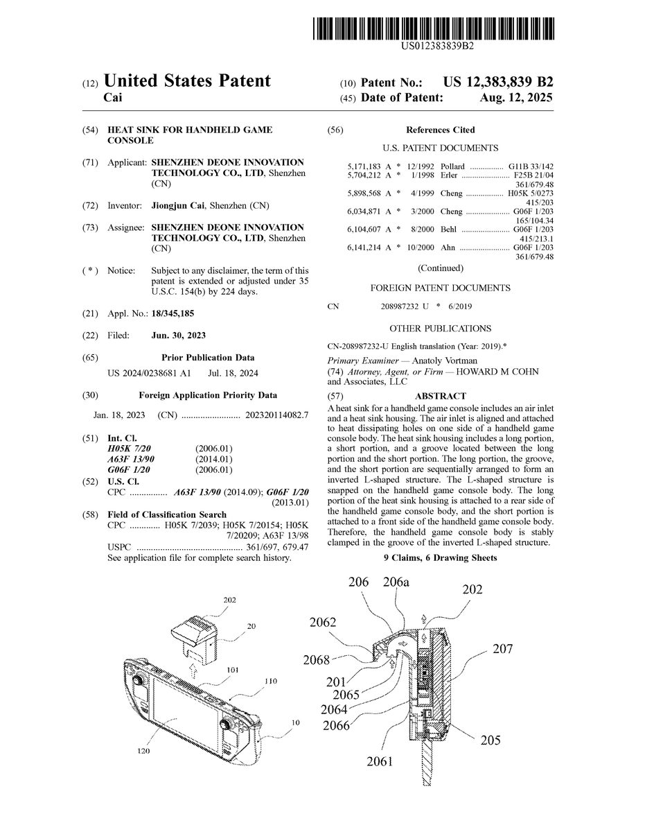
A heat sink for a handheld game console includes an air inlet and a heat sink housing. The air inlet is aligned and attached to heat dissipating holes on one side of a handheld game console body. The heat sink housing includes a long portion, a short portion, and a groove located between the long portion and the short portion. The long portion, the groove, and the short portion are sequentially arranged to form an inverted L-shaped structure. The L-shaped structure is snapped on the handheld game console body. The long portion of the heat sink housing is attached to a rear side of the handheld game console body, and the short portion is attached to a front side of the handheld game console body. Therefore, the handheld game console body is stably clamped in the groove of the inverted L-shaped structure.
Description
DETAILED DESCRIPTION In order to well understand the purpose, structure, features and functions of the present disclosure, a heat sink for a handheld game console of the present disclosure will be further described in conjunction with the accompanying drawings and specific embodiments. As shown inFIGS.1-7, the present disclosure provides the heat sink for the handheld game console. The handheld game console comprises a handheld game console body10and heat dissipating holes101defined on one side of the handheld game console body10. The heat sink comprises a heat sink housing20, an air inlet201defined on a surface of the heat sink housing20, an air outlet202defined on the surface of the heat sink housing20, a heat dissipating fan203arranged in the heat sink housing20, and a circuit board204arranged in the heat sink housing20. A flow guide groove205is formed between the air inlet201and the air outlet202. The heat dissipating fan203is connected to the flow guide groove205to form a flow guide cavity. The air inlet201is connected to the heat dissipating holes101on the one side of the handheld game console body10. In the embodiment, the handheld game console body10comprises four sides, which are respectively a top side, a bottom side, a left side, and a right side. Any two sides arranged opposite to each other, of the four sides, are parallel to each other, and the heat dissipating holes101of the handheld game console body10are defined on the top side of the handheld game console body10. Of course, in other embodiments, the heat dissipating holes101of the handheld game console body may also be defined on other side of the handheld game console body10, such as the bottom side, the left side, or the right side of the handheld game console body10, which is not limited thereto. The air inlet201and the air outlet202of the heat sink are defined on the surface ...
DETAILED DESCRIPTION
In order to well understand the purpose, structure, features and functions of the present disclosure, a heat sink for a handheld game console of the present disclosure will be further described in conjunction with the accompanying drawings and specific embodiments.
As shown inFIGS.1-7, the present disclosure provides the heat sink for the handheld game console. The handheld game console comprises a handheld game console body10and heat dissipating holes101defined on one side of the handheld game console body10. The heat sink comprises a heat sink housing20, an air inlet201defined on a surface of the heat sink housing20, an air outlet202defined on the surface of the heat sink housing20, a heat dissipating fan203arranged in the heat sink housing20, and a circuit board204arranged in the heat sink housing20. A flow guide groove205is formed between the air inlet201and the air outlet202. The heat dissipating fan203is connected to the flow guide groove205to form a flow guide cavity. The air inlet201is connected to the heat dissipating holes101on the one side of the handheld game console body10.
In the embodiment, the handheld game console body10comprises four sides, which are respectively a top side, a bottom side, a left side, and a right side. Any two sides arranged opposite to each other, of the four sides, are parallel to each other, and the heat dissipating holes101of the handheld game console body10are defined on the top side of the handheld game console body10. Of course, in other embodiments, the heat dissipating holes101of the handheld game console body may also be defined on other side of the handheld game console body10, such as the bottom side, the left side, or the right side of the handheld game console body10, which is not limited thereto.
The air inlet201and the air outlet202of the heat sink are defined on the surface of the heat sink housing20. The heat dissipating fan203and the circuit board204of the heat sink are arranged inside the heat sink housing20. The flow guide groove is U-shaped and is formed between the air inlet201and the air outlet202. A rear portion of the flow guide groove205is attached to an inner side surface of the heat sink housing20to form a closed side surface. A front portion of the flow guide groove205defines an open portion. The open portion faces the air inlet201. A top portion of the flow guide groove205defines a top opening. The top opening faces the air outlet202. The heat dissipating fan203is connected to the flow guide groove205to form the flow guide cavity. Specifically, the heat dissipating fan203is connected to the open portion on the front portion of the flow guide groove205to form the flow guide cavity. A front surface of the heat dissipating fan203faces the open portion. The air inlet201is connected to the heat dissipating holes101defined on the one side of the handheld game console body10. Specifically, the air inlet201is aligned with and attached to the heat dissipating holes101on the one side of the handheld game console body10. An opening area of the air inlet201is not less than an opening area of the heat dissipating holes101on the one side of the handheld game console body10.
By defining the flow guide groove205between the air inlet201and air outlet202of the heat sink for the handheld game console, the heat dissipating fan203is connected to the flow guide groove205to form the flow guide cavity, so that the air inlet201is connected to the heat dissipating holes101on the one side of the handheld game console body10. Through rotation of the heat dissipating fan203, air inside the handheld game console is introduced into the flow guide cavity, and the heat dissipating fan203accelerates and guides the air, so that the air is discharged through the air outlet202, which in turn enables heat inside the handheld game console to be completely discharged from the heat sink housing in time, thereby effectively avoiding the handheld game console from being under a high temperature environment for a long time. Therefore, shortening of service life of components inside the handheld game console and burning out of the handheld game console are avoided.
As shown inFIGS.4-7, the heat dissipating fan203comprises a heat dissipating fan shell and fan blades. The heat dissipating fan shell comprises an air inlet flow guide port and an air outlet flow guide port. The fan blades are arranged at the air inlet flow guide port. The air inlet flow guide port faces the air inlet201. The air outlet flow guide port faces the air outlet202. The air inlet flow guide port is connected to the flow guide groove205to form the flow guide cavity.
In the embodiment, the air inlet flow guide port is connected to the flow guide groove205to form the flow guide cavity. The air inlet flow guide port is connected and attached to the flow guide groove205. Of course, in other embodiments, the air inlet flow guide port is clamped with the flow guide groove205or the air inlet flow guide port is connected to the flow guide groove205by another connection mode, which is not limited thereto. Through rotation of the fan blades, the air inside the handheld game console is introduced into the flow guide cavity, and the heat dissipating fan203accelerates and guides the air, so that the air is discharged through the air outlet202, which in turn enables the heat inside the handheld game console to be completely discharged from the heat sink housing.
In one optional embodiment of the present disclosure, an area of the air inlet flow guide port matches an area of the fan blades. Specifically, the area of the air inlet flow guide port is equal to an area of a circle formed by combining the fan blades. Of course, in other embodiments, the area of the air inlet flow guide port maybe greater than the area of the circle formed by combining the fan blades, or the area of the air inlet flow guide port may be less than the area of the circle formed by combining the fan blades, which is not limited thereto.
As shown inFIGS.5-7, the heat sink housing20comprises a bottom shell206and a top cover207, the bottom shell206and the top cover207are connected to form an accommodating cavity. The bottom shell206is connected to the top cover207through fasteners210. Of course, in other embodiments, the bottom shell206is clamped with the top cover207or the bottom shell206is bonded to the top cover207, which is not limited thereto. The heat dissipating fan203and the circuit board204are arranged in the accommodating cavity. An outer side surface of the bottom shell206is attached to the handheld game console body10. The flow guide groove205is defined on a surface, facing the accommodating cavity, of the bottom shell206. The air inlet flow guide port is connected to the flow guide groove205to form the flow guide cavity.
In one optional embodiment of the present disclosure, the air inlet flow guide port is attached to a groove surface of the flow guide groove205to form the flow guide cavity. Of course, in other embodiments, the air inlet flow guide port may be connected to the groove surface of the flow guide groove205in other forms, e.g., the air inlet flow guide port may be clamped with the groove surface of the flow guide groove205or the air inlet flow guide port may be embedded in the groove surface of the flow guide groove205, which is not limited thereto.
As shown inFIGS.1-6, the air inlet201is defined on the bottom shell206. The air inlet201is matched with and connected to the heat dissipating holes101on the one side of the handheld game console body10. The air outlet202is defined on the top side surface206aof the bottom shell206. The air outlet202is away from the air inlet201. Of course, in other embodiments, the air inlet201may be defined on the bottom shell206of the heat sink for the handheld game console, and the air outlet202is defined on the top cover207. Alternatively, the air outlet202is defined on the bottom shell206and the top cover207of the heat sink for the handheld game console, which is not limited thereto.
In the embodiment, the heat sink housing20comprises a long portion2061, a short portion2062, and a groove2063located between the long portion2061and the short portion2062. The short portion2062is arranged adjacent to the groove2063. The groove2063is arranged adjacent to the long portion2061. The long portion2061, the groove2063, and the short portion2062are sequentially arranged to form an inverted L-shaped structure. The inverted L-shaped structure is snapped on the handheld game console body10.
In one optional embodiment of the present disclosure, the long portion2061, the groove2063, and the short portion2062of the heat sink housing20are integrally formed. Specifically, the heat sink housing20comprises the long portion2061, the short portion2062, and the groove2063located between the long portion2061and the short portion2062. The short portion2062is arranged adjacent to the groove2063. The groove2063is arranged adjacent to the long portion2061. The long portion2061, the groove2063, and the short portion2062are sequentially arranged to form the inverted L-shaped structure. The bottom shell206of the inverted L-shaped structure is snapped on the handheld game console body10.
Furthermore, the groove2063comprises an inner side surface2064. The air inlet201is defined on a bottom portion2065of the inner side surface2064of the groove2063. The air outlet202is defined on the top side surface206aof the bottom shell206. The inner side surface2064of the groove2063is attached to the one side of the handheld game console body where the heat dissipating holes are defined. The air inlet201is attached to the heat dissipating holes defined on the one side of the handheld game console body.
The long portion2061comprises a first side surface2066arranged adjacent to the inner side surface2064of the groove2063and a second side surface2067connected to the first side surface2066. The first side surface2066of the long portion2061is attached to a rear side110of the handheld game console body10.
The short portion2062comprises a third side surface2068arranged adjacent to the inner side surface of the groove2063and a fourth side surface2069connected to the third side surface2068. The third side surface2068is attached to a front side120of the handheld game console body10.
In the embodiment, the heat sink housing20is arranged in the inverted L-shaped structure, so that the long portion2061of the heat sink housing20is attached to the rear side110of the handheld game console body10, and the short portion2062is attached to the front side120of the handheld game console body10. Therefore, the handheld game console body10is clamped in the groove2063of the inverted L-shaped structure of the heat sink housing20, thereby effectively clamping the handheld game console body10and preventing the heat sink from falling off from the handheld game console body10.
In one optional embodiment of the present disclosure, the heat dissipating fan203and the circuit board204are arranged in the long portion2061of the heat sink housing20. Specifically, the heat dissipating fan203is arranged in an upper half space of the long portion2061of the heat sink housing20. The circuit board204is arranged in a lower half space of the long portion2061of the heat sink housing20.
In the embodiment, the heat dissipating fan203and the circuit board204are arranged in the long portion2061of the heat sink housing20, so that a center of gravity of the heat sink falls on the rear side110of the handheld game console body10, thereby further preventing the heat sink from falling off from the handheld game console body10and the heat sink is clamped firmly.
As shown inFIGS.6-7, a fan speed regulator is arranged on the circuit board204, and the fan speed regulator is configured to adjust a rotation speed of the heat dissipating fan203.
In the embodiment, the fan speed regulator is a knob switch. The knob switch is electrically connected to the circuit board204. The rotation speed of the heat dissipating fan203is adjusted by rotating the knob switch.
To sum up, in the heat sink for the handheld game console of the present disclosure, the heat sink housing is arranged in the inverted L-shaped structure, so that the long portion of the heat sink housing is attached to the rear side110of the handheld game console body, and the short portion is attached to the front side120of the handheld game console body. Therefore, the handheld game console body is clamped in the groove of the inverted L-shaped structure of the heat sink housing. Moreover, the heat dissipating fan and the circuit board are arranged in the long portion of the heat sink housing, so that the center of the gravity of the heat sink falls on the rear side of the handheld game console body, thereby further preventing the heat sink from falling off from the handheld game console body and the heat sink is clamped firmly.
The above detailed description is only a description of optional embodiments of the present disclosure, and does not limit the patent scope of the present disclosure. Therefore, all equivalent technical changes made based on the description and illustrations of the present disclosure are included in the protection scope of the present disclosure.
Claims
- A heat sink for a handheld game console defining a handheld game console body and heat dissipating holes defined on one side of the handheld game console body, comprising: a heat sink housing, an air inlet defined on a surface of the heat sink housing, an air outlet defined on the surface of the heat sink housing, a heat dissipating fan arranged in the heat sink housing, and a circuit board arranged in the heat sink housing;wherein the air inlet is aligned and attached to the heat dissipating holes on the one side of the handheld game console body;the heat sink housing comprises a long portion, a short portion, and a groove located between the long portion and the short portion;the short portion is arranged adjacent to the groove;the groove is arranged adjacent to the long portion;the long portion, the groove, and the short portion are sequentially arranged to form an inverted L-shaped structure;the inverted L-shaped structure is snapped on the handheld game console body.
- The heat sink according to claim 1, wherein the groove comprises an inner side surface;the inner side surface of the groove is attached to the one side of the handheld game console body, and the heat dissipating holes are on the one side of the handheld game console body.
- The heat sink according to claim 2, wherein the air inlet is defined on a bottom portion of the inner side surface of the groove.
- The heat sink according to claim 3, wherein the long portion comprises a first side surface arranged adjacent to the inner side surface of the groove and a second side surface connected to the first side surface of the long portion;the first side surface of the long portion is attached to a rear side of the handheld game console body.
- The heat sink according to claim 4, wherein the short portion comprises a third side surface arranged adjacent to the inner side surface of the groove and a fourth side surface connected to the third side surface of the short portion;the third side surface is attached to a front side of the handheld game console body.
- The heat sink according to claim 1, wherein the heat sink housing comprises a bottom shell and a top cover;the bottom shell comprises the long portion, the short portion, and the groove arranged between the long portion and the short portion.
- The heat sink according to claim 6, wherein the bottom shell and the top cover are connected to form an accommodating cavity;the heat dissipating fan and the circuit board are arranged in the accommodating cavity.
- The heat sink according to claim 7, wherein the bottom shell is connected to the top cover through fasteners.
- The heat sink according to claim 6, wherein the air outlet is defined on a top side surface of the bottom shell.
Disclaimer: Data collected from the USPTO and may be malformed, incomplete, and/or otherwise inaccurate.