U.S. Pat. No. 12,370,456
DRY BAG FOR GAME CONTROLLER
Issue DateJuly 12, 2023
Illustrative Figure
Abstract
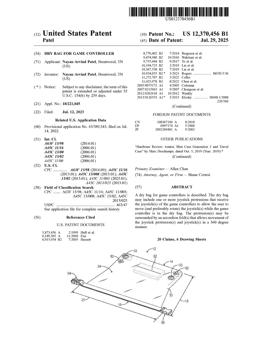
A dry bag for game controllers is described. The dry bag may include one or more joystick protrusions that receive the joystick(s) of the game controllers to allow the user to move (and preferably rotate) the joystick(s) while the game controller is in the dry bag. The protrusion(s) may be surrounded by an accordion fold(s) that allows movement of the joystick protrusion(s) and joystick(s) in a 360 degree manner.
Description
DETAILED DESCRIPTION With reference toFIGS.1-11the present disclosure provides a dry bag generally denoted by the numeral12for providing a waterproof/water-resistant environment for a game controller10. In the drawings, not all reference are included in all drawings for clarity. In addition, the drawings are drawn to scale but other dimensions are possible. As shown inFIGS.1-11, like a typical dry bag, the dry bag12may comprise a closed bottom14, an open top16, a length18extending from the closed bottom14to the open top16, a width20perpendicular to the length18, a thickness22perpendicular to the length18and width20, at least one flexible wall24that may extend about the length18, width20and thickness22and provide a flexible waterproof/water-resistant barrier26separating a bag exterior28from a bag interior30. The bag interior30is preferably configured to hold a game controller10. The dry bag12may also include a fastener32that may be configured to seal the dry bag12. As shown inFIGS.1-11, the fastener32may be attached to the at least one flexible wall24and may be located adjacent the open top16. As shown inFIGS.3-5, a user may use the dry bag12by inserting the game controller10through the open top16and into the bag interior30so that the game controller10confronts the bag bottom14. Then, as shown inFIG.6, a user may fold the open top16toward the closed bottom14and connect the fastener32to seal the open top16, like a typical dry bag12. Optionally, as shown inFIGS.1-11, the at least one flexible sidewall24is comprised of a front panel50and a rear panel52. Optionally, as shown inFIGS.1-11, the fastener is a buckle32. Optionally, as shown inFIGS.1-11, the front panel50and rear panel52are connected and are separated by the bag interior30and the buckle32is comprised of a buckle hook54(male member) and buckle receptacle56(female member) configured to releasably receive the hook54and the hook and receptacle54/56are connected to opposite sides of the front panel50and the rear panel52. Optionally, as shown inFIGS.1-11, the entire at least one flexible wall24(or at ...
DETAILED DESCRIPTION
With reference toFIGS.1-11the present disclosure provides a dry bag generally denoted by the numeral12for providing a waterproof/water-resistant environment for a game controller10. In the drawings, not all reference are included in all drawings for clarity. In addition, the drawings are drawn to scale but other dimensions are possible.
As shown inFIGS.1-11, like a typical dry bag, the dry bag12may comprise a closed bottom14, an open top16, a length18extending from the closed bottom14to the open top16, a width20perpendicular to the length18, a thickness22perpendicular to the length18and width20, at least one flexible wall24that may extend about the length18, width20and thickness22and provide a flexible waterproof/water-resistant barrier26separating a bag exterior28from a bag interior30. The bag interior30is preferably configured to hold a game controller10. The dry bag12may also include a fastener32that may be configured to seal the dry bag12. As shown inFIGS.1-11, the fastener32may be attached to the at least one flexible wall24and may be located adjacent the open top16.
As shown inFIGS.3-5, a user may use the dry bag12by inserting the game controller10through the open top16and into the bag interior30so that the game controller10confronts the bag bottom14. Then, as shown inFIG.6, a user may fold the open top16toward the closed bottom14and connect the fastener32to seal the open top16, like a typical dry bag12.
Optionally, as shown inFIGS.1-11, the at least one flexible sidewall24is comprised of a front panel50and a rear panel52. Optionally, as shown inFIGS.1-11, the fastener is a buckle32. Optionally, as shown inFIGS.1-11, the front panel50and rear panel52are connected and are separated by the bag interior30and the buckle32is comprised of a buckle hook54(male member) and buckle receptacle56(female member) configured to releasably receive the hook54and the hook and receptacle54/56are connected to opposite sides of the front panel50and the rear panel52.
Optionally, as shown inFIGS.1-11, the entire at least one flexible wall24(or at least the portion directly in front of the game controller10) is transparent to allow the user to see the game controller10in the dry bag12.
Optionally, the game controller10is a wireless game controller and comprises a transmitter, which allows the game controller10to be played without taking the game controller10outside of the bag12.
As known in the art, game controllers10typically include one or more joysticks34and/or one or more buttons84. Optionally, preferably, unlike typical dry bags12, as shown inFIGS.1-11, the at least one flexible wall24further comprises one or more joystick protrusions33that extend laterally outward (i.e., away from the bag interior30) and are configured to receive a joystick34and allow the user to move the respective joystick34within the joystick protrusion(s)33. For example, in some embodiments, as shown inFIGS.1-11, the joystick protrusions33are generally cylindrical in shape and comprise a generally circular top35, a base36, and a sidewall38located between the top35and the base36. Optionally, as shown inFIGS.1-11, the at least one flexible sidewall24comprises at least one accordion fold adjacent to the base36of each joystick protrusion33. More particularly, in some embodiments, as shown inFIGS.1-11, the at least one flexible sidewall24further comprises two generally circular troughs40, each of which extends around a circumference of the base36of the joystick protrusion33, and two ridges42, each of which extends around a circumference of a generally circular trough40. Optionally, each generally circular top35is configured to tilt toward a generally circular ridge42in any direction about the circumference of the generally circular ridge42to allow 360 degree movement of the joystick34. Optionally, the method further comprises tilting the generally circular top35and the joystick34towards a first location of the ridge42while in the at least one joystick protrusion33. The movement of the joystick34and joystick protrusion33is best seen by comparingFIG.8withFIG.7. Optionally, the ridge42comprises a height parallel to the dry bag thickness22, the height of the ridge42increases at the first location of the ridge42as the generally circular top35tilts toward the first location (left ridge inFIG.8) and, as best seen inFIG.8, the height of the ridge42decreases at a second location of the ridge (right ridge inFIG.8) located 180 degrees from the first location as the generally circular top35tilts away from the second location. Optionally, at rest, the ridge42is an inverted v-shaped accordion fold, as best seen inFIGS.7and11. Optionally, the at least one joystick protrusion33, trough40and ridge42are a single piece of material. Optionally, as best seen inFIG.11, the joystick protrusion33comprises a height extending from the base36to the generally circular top35and the protrusion height is parallel to the dry bag thickness22. Optionally, as shown inFIGS.1-11, the at least one joystick protrusion33is located on the front panel50. Optionally, the joystick protrusion33is closer to the bottom14than the open top16.
Optionally, as shown inFIGS.1-11, the at least one flexible wall24further comprises at least two button protrusions82extending laterally outward to receive buttons of the game controller84(to allow the user to push the buttons through the dry bag12). Optionally, the button protrusions82are generally circular in shape. Optionally, as shown inFIGS.1-11, at least one group of the button protrusions82is located between the closed bottom14and the joystick protrusion33and at least one group of the button protrusions82is located between the open top16and the joystick protrusion33. Optionally, the joystick protrusion(s)33extends laterally outward to a greater degree than the button protrusions82(e.g., has a greater height). Optionally, the joystick34and button protrusions82are molded (in order to fit the contours of the controller10). Optionally, the joystick protrusion(s)33and the button protrusions82have a length parallel to the length of the dry bag12and the length of the joystick protrusion(s)33is greater than the length of each of the two button protrusions82.
Optionally, prior to inserting the game controller10, the dry bag12tapers in decreasing height from adjacent the joystick protrusion33toward the open top16(e.g., from the top-most protrusion33to the open top16). Optionally, prior to inserting the game controller10, the dry bag12tapers in increasing width20from a location adjacent the closed bottom14toward the open top16(in order to allow enough slack to allow the game controller10be pushed into place). Optionally, prior to inserting the game controller10, the closed bottom14is rectangular in shape, and the game controller10is generally rectangular in shape (so the dry bag12is form fitting around the rectangular controller10so air does not get trapped). Optionally, prior to inserting the game controller10, the length18of the dry bag12is between about 8 inches and about 16 inches. Optionally, after folding the open top16toward the closed bottom14and connecting the fastener32to seal the open top16the length of the dry bag18is the length of the controller10plus approximately 1 inch to 4 inches to allow for folded up dry bag12and buckle32.
Optionally, as shown inFIGS.1-11, the dry bag12further comprises a floatation aid62connected to the rear panel52, the floatation aid62is buoyant and configured to allow the dry bag12with included game controller10to float in water. Optionally, the floatation aid62is adjacent the open top16.
The at least one flexible wall24may be comprised of any suitable material, including, for example, one or more of nylon, vinyl, polyethylene, polyvinyl chloride or such like material that provides flexibility while holding some form. Optionally, the at least one flexible wall24is comprised of a plurality of materials.
Optionally, as shown inFIG.6, the dry bag12further comprises a loop or wrist strap80connected to the at least one flexible wall24, the loop80configured to receive a user's wrist. Optionally, the loop80is located adjacent to the open top16. Optionally the method further comprises placing a user's hand through the loop80.
Optionally, the game controller10comprises a left side44, a right side46, and a game controller width48extending from the left side to the right side, and, as shown inFIG.4, the game controller width48is substantially equal to the width of the closed bottom14(so air does not get trapped—e.g., the closed bottom width is no more than about 0.5 inches greater than the game controller width48).
Part ListGame controller10Dry bag12Dry bag closed bottom14Dry bag open top16Dry bag length18Dry bag width20Dry bag thickness22Flexible wall24Flexible waterproof/water-resistant barrier26Dry bag exterior28Dry bag interior30Fastener/Buckle32Joystick protrusion33Joystick34Joystick protrusion circular top35Joystick protrusion base36Joystick protrusion flexible sidewall38Circular trough40Circular ridge42Game controller left side44Game controller right side46Game controller width48Flexible sidewall front panel50Flexible sidewall rear panel52Buckle hook54Buckle receptacle56Dry bag loop60Floatation aid62Loop/wrist strap80Button Protrusion82Controller Button84
Having now described the invention in accordance with the requirements of the patent statutes, those skilled in the art will understand how to make changes and modifications to the disclosed embodiments to meet their specific requirements or conditions. Changes and modifications may be made without departing from the scope and spirit of the invention. In addition, the steps of any method described herein may be performed in any suitable order and steps may be performed simultaneously if needed. Use of the singular embraces the plural.
Terms of degree such as “generally”, “substantially”, “about”, and “approximately” as used herein mean a reasonable amount of deviation of the modified term such that the end result is not significantly changed. For example, these terms can be construed as including a deviation of at least ±5% of the modified term if this deviation would not negate the meaning of the word it modifies.
Claims
- A method of providing a waterproof/water-resistant environment for a game controller comprising the steps of: a) providing a game controller, the game controller comprising at least one joystick;b) providing a dry bag comprising a closed bottom, an open top, a length extending from the closed bottom to the open top, a width perpendicular to the length, a thickness perpendicular to the length and width, at least one flexible sidewall providing a flexible waterproof/water-resistant barrier separating a bag exterior from a bag interior, the bag interior configured to hold the game controller, and a fastener located adjacent the open top, wherein the at least one flexible sidewall further comprises at least one joystick protrusion extending laterally outward and configured to receive the at least one joystick, wherein the at least one joystick protrusion is generally cylindrical in shape and comprises a generally circular top, a base, and a protrusion sidewall located between the top and the base, and wherein the at least one flexible sidewall further comprises a generally circular trough extending around a circumference of the base of the at least one joystick protrusion and a ridge extending around a circumference of the generally circular trough;c) placing the game controller in the bag interior so that the at least one joystick is located in the at least one joystick protrusion;and d) folding the open top toward the closed bottom and connecting the fastener to seal the open top.
- The method of claim 1 wherein the ridge is generally circular in shape and comprises a circumference, and further wherein the generally circular top is configured to tilt toward the generally circular ridge in any direction about the circumference of the generally circular ridge to allow 360 degree movement of the at least one joystick.
- The method of claim 1 wherein the method further comprises tilting the generally circular top and the at least one joystick towards a first location of the ridge while in the at least one joystick protrusion.
- The method of claim 3 wherein the ridge comprises a height parallel to the dry bag thickness, wherein the height of the ridge increases at the first location of the ridge as the generally circular top tilts toward the first location and wherein the height of the ridge decreases at a second location of the ridge located 180 degrees from the first location as the generally circular top tilts away from the second location.
- The method of claim 1 wherein the ridge is an inverted v-shaped accordion fold.
- The method of claim 1 wherein the at least one joystick protrusion, trough and ridge are a single piece of material.
- The method of claim 1 wherein the joystick protrusion comprises a height extending from the base to the generally circular top and further wherein the protrusion height is parallel to the dry bag thickness.
- The method of claim 1 wherein the at least one flexible sidewall comprises at least one accordion fold adjacent to the base of the at least one joystick protrusion.
- The method of claim 1 wherein the at least one flexible sidewall is comprised of a front panel and a rear panel.
- The method of claim 9 wherein the at least one joystick protrusion is located on the front panel.
- The method of claim 10 wherein the fastener is a buckle, wherein the front panel and rear panel are connected and are separated by the bag interior and further wherein the buckle is comprised of a buckle hook and buckle receptacle configured to releasably receive the hook and further wherein the hook and receptacle are connected to opposite sides of the front panel and the rear panel.
- The method of claim 1 wherein the dry bag further comprises a floatation aid connected to the rear panel, the floatation aid buoyant and configured to allow the dry bag with included game controller to float in water.
- The method of claim 1 wherein, in step a), the dry bag tapers in increasing width from a location adjacent the closed bottom toward the open top.
- The method of claim 13 wherein the game controller comprises a left side, a right side, and a game controller width extending from the left side to the right side, and further wherein the game controller width is substantially equal to the width of the closed bottom.
- The method of claim 1 wherein at least the portion of the at least one flexible sidewall located in front of the game controller is transparent.
- The method of claim 1 wherein the entire at least one flexible sidewall is transparent.
- The method of claim 1 wherein in step a) the closed bottom is generally rectangular in shape.
- The method of claim 17 wherein the game controller is generally rectangular in shape, and the dry bag is form fitting around the rectangular controller so air does not get trapped.
- The method of claim 1 wherein the at least one joystick protrusion is closer to the bottom than the open top.
- The method of claim 1 wherein the game controller is a wireless game controller and comprises a transmitter.
Disclaimer: Data collected from the USPTO and may be malformed, incomplete, and/or otherwise inaccurate.