U.S. Pat. No. 12,337,230
GAME CONTROLLER AND KEY THEREOF
AssigneeSHENZHEN GULI TECHNOLOGY CO., LTD.
Issue DateMay 9, 2023
Illustrative Figure
Abstract
A game controller key includes a base, a casing and a key switch. The casing is fastened to the base to form a cavity; the key switch is disposed in the cavity; the top of the key switch is exposed from a surface of the casing; conductive silica gel is installed at the bottom of the key switch; a through hole is provided at a position on the base that corresponds to the conductive silica gel; a spring is installed between the key switch and the base; a side wall of the key switch is provided with a first bump; a plate body is installed on the base; a gap is present between each of two sides of the plate body and the base; and the plate body is provided with a second bump matching the first bump. The spring is used for controlling the force of the key.
Description
Signs in figures:1—base;2—casing;3—key switch;4—conductive silica gel;5—spring;6—first bump;7—plate body;8—gap;9—second bump;31—cross switch;32—switch shell;33—sleeve;10—dustproof cap;21—clamping groove;11—clamping hook; and12—step. DETAILED DESCRIPTION OF THE EMBODIMENTS In order to enable those in the technical field to better understand the present application solutions, the technical solutions in the embodiment of the present application will be clearly and completely described in combination with the drawings in the embodiment of the present application. Obviously, the described embodiment is only a part of the embodiments of the present application, not all of the embodiments. Based on the embodiments in the present application, all other embodiments obtained by ordinary technicians in the art without creative efforts should fall within the scope of protection in the present application. It is to be noted that the terms “first”, “second” and the like in the description and claims of the present application and the above drawings are used for distinguishing similar objects, and need not be used to describe a specific order or sequence It is to be understood that the number used in this way can be interchanged under appropriate circumstances to facilitate the embodiments of the present application described herein. In addition, the terms “including” and “having” as well as any variation of them are intended to cover non-exclusive inclusion. For example, a process, method, system, product or device that contains a series of steps or units need not be limited to those steps or units that are clearly listed, but may include other steps or units that are not clearly listed or are inherent in these processes, methods, products or devices. In the present application, the terms “installation”, “provide”, “dispose”, “connection” and “linkage” should be understood broadly. For example, “connection” can be fixed connection, removable connection, or integral structure; it can be mechanical connection or electrical connection; it can be direct ...
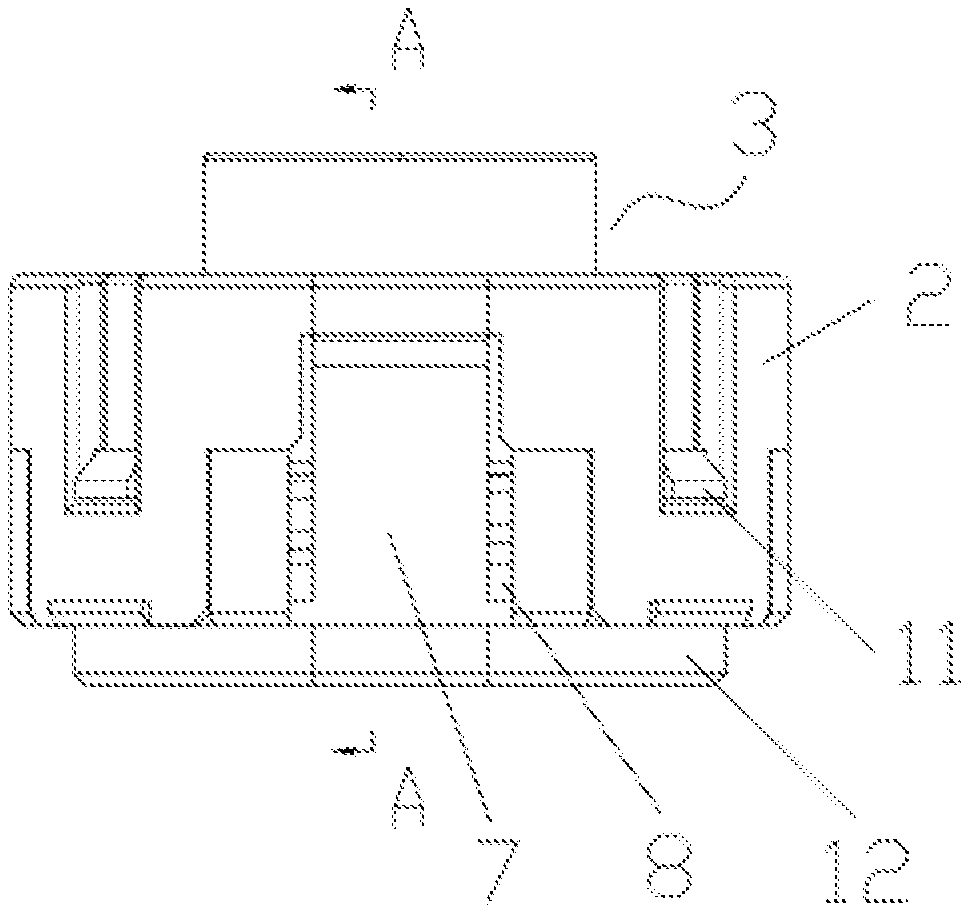
Signs in figures:1—base;2—casing;3—key switch;4—conductive silica gel;5—spring;6—first bump;7—plate body;8—gap;9—second bump;31—cross switch;32—switch shell;33—sleeve;10—dustproof cap;21—clamping groove;11—clamping hook; and12—step.
DETAILED DESCRIPTION OF THE EMBODIMENTS
In order to enable those in the technical field to better understand the present application solutions, the technical solutions in the embodiment of the present application will be clearly and completely described in combination with the drawings in the embodiment of the present application. Obviously, the described embodiment is only a part of the embodiments of the present application, not all of the embodiments. Based on the embodiments in the present application, all other embodiments obtained by ordinary technicians in the art without creative efforts should fall within the scope of protection in the present application.
It is to be noted that the terms “first”, “second” and the like in the description and claims of the present application and the above drawings are used for distinguishing similar objects, and need not be used to describe a specific order or sequence It is to be understood that the number used in this way can be interchanged under appropriate circumstances to facilitate the embodiments of the present application described herein. In addition, the terms “including” and “having” as well as any variation of them are intended to cover non-exclusive inclusion. For example, a process, method, system, product or device that contains a series of steps or units need not be limited to those steps or units that are clearly listed, but may include other steps or units that are not clearly listed or are inherent in these processes, methods, products or devices.
In the present application, the terms “installation”, “provide”, “dispose”, “connection” and “linkage” should be understood broadly. For example, “connection” can be fixed connection, removable connection, or integral structure; it can be mechanical connection or electrical connection; it can be direct connection, indirect connection through an intermediate medium, or internal connection between two devices, elements or components. For those skilled in the art, the specific meaning of the above terms in the present application can be understood according to the specific situation.
It is noted that the embodiments in the present application and the features in the embodiments can be combined with each other without conflict. The present application will be described in detail below with reference to the accompanying drawings and in combination with embodiments.
According to the embodiments of the present application, as shown inFIGS.1-5, a game controller key in the present application includes a base1, a casing2and a key switch3; the casing2is fastened on the base1to form a cavity; the key switch3is disposed in the cavity; the top of the key switch3is exposed from a surface of the casing2; conductive silica gel4is installed at the center of the bottom of the key switch3; a through hole is provided at a position on the base1that corresponds to the conductive silica gel4; a spring5is installed between the key switch3and the base1; a side wall of the key switch3is provided with a first bump6; a plate body7is installed on the base1; a gap8is present between each of two sides of the plate body7and the base1; and the plate body7is provided with a second bump9matching the first bump6. The gap8is present, so that when the key switch3is pressed, the spring5is compressed, the key switch3extrudes the second bump9outwards through the first bump6, the plate body7is driven to incline outwards by the second bump9, and thus the force curve of a traditional conductive adhesive can be simulated.
The spring5is used for controlling the force of the key switch3, the characteristics of good production consistency and long service life of the spring5are utilized, and the force of the spring5can be conveniently adjusted, so that various keys with different forces can be conveniently produced.
The key switch3is independently made, and meanwhile, the problems of key clamping, abrasion and uneven pressing of a key cap of a traditional game controller key are solved.
The key switch is independently made, so that the key cap can be conveniently replaced, and rapid mass production and personalized customization are realized.
Specifically, the key switch3includes a cross switch31, a switch shell32and a sleeve33; the cross switch31is installed on the top of the switch shell32; the sleeve33is installed at the center of the bottom of the switch shell32; the conductive silica gel4is installed in the sleeve33; the top of the cross switch31is exposed from the surface of the casing2; the spring5is installed between the switch shell32and the base1; and the first bump6is disposed on the side wall of the switch shell32.
The conductive silica gel4is used in the center part, and a contact of a contact circuit is still conductive adhesive, so that the hand feeling and the mute are guaranteed; and because the design of a traditional silica gel bowl is omitted, the silica gel bowl structure part which is most prone to breakage is avoided.
Preferably, in the present application, the first bumps6are disposed on four side walls of the switch shell32, and two plate bodies7are installed at the positions, corresponding to the two opposite first bumps6, of the base1. According to the present application, the four first bumps6are disposed, so that production is facilitated and the installing efficiency is ensured; the four first bumps6guarantee that the switch shell32is directly connected with the base1without considering whether the first bumps6correspond to second bumps9on the plate bodies7or not, and the installation efficiency is improved.
Preferably, in the present application, the number of the second bumps9on the plate bodies7can be consistent with that of the first bumps6, namely the number of the second bumps9and the number of the first bumps6are both four, but pressing the key switch3is strenuous due to such arrangement.
Preferably, in the present application, the number of the first bumps6of the switch shell32and the number of the second bumps9on the plate bodies7can be odd, such as one or three, but the key switch3is unevenly stressed during pressing, and abrasion of the first bumps6and the second bumps9is aggravated because of such number.
Specifically, the game controller key further includes a dustproof cap10, and the dustproof cap10sleeves and disposed outside the cross switch31and is connected with the switch shell32, so that dust can be effectively prevented from entering, and the service life is prolonged.
Specifically, the casing2is detachably connected with the base1, which facilitates installing and replacing the key switch3.
Specifically, a clamping groove21is formed in the casing2; a clamping hook11matching the clamping groove21is disposed on the base1; and the base1is connected with the clamping groove21of the casing2through the clamping hook11.
Preferably, four clamping grooves21are disposed in the casing2and four clamping hooks11are disposed on the base1, and thus the connection stability of the casing2and the base1is guaranteed.
Specifically, the casing2and the base1are both rectangular, which can effectively prevent the interference problem during key layout.
Specifically, because the casing2and the base1are both rectangular, the cavity formed by the casing2and the base1is also rectangular, thus the switch shell32is also rectangular, and matching of the switch shell32and the cavity is guaranteed.
Specifically, the first bump6and the second bump9are both hemispherical.
Specifically, the first bump6and the second bump9are both made of POM plastic, and the POM plastic is good in toughness, resistant to abrasion and long in service life.
Specifically, a step12is disposed at the bottom of the base1; and due to the step12, the key can be installed at the top or the bottom, so that the game controller with different modes and functions can be designed.
Specifically, one end, far away from the casing2, of the plate body7is connected to the base1, and the plate body7and the base1are of an integrated structure.
One end, far away from the casing2, of the plate body7is connected to the base1, so that when the key switch3extrudes the second bump9outwards through the first bump6, the second bump9easily drives the plate body7to incline outwards; and the plate body7and the base1are of an integrated structure, so the structural strength can be improved.
Specifically, in order to facilitate relative sliding between the first bump6and the second bump9, the surface of the first bump6and the surface of the second bump9are curved surfaces.
Specifically, the through hole is formed on the casing2; the cross switch31and the dustproof cap10are exposed from the through hole which extends out of the casing2; and the outer surface of the dustproof cap10is attached to the inner surface of the through hole of the casing2.
The outer surface of the dustproof cap10is attached to the inner surface of the through hole of the casing2, so that the dustproof cap10can seal the gap between the key switch3and the through hole of the casing2, and dust is prevented from entering.
Specifically, in order to facilitate manufacturing of the key switch3, the cross switch31, the dustproof cap10, the switch shell32and the sleeve33can be of an integrated structure, and thus the key switch3can be integrally formed during manufacturing.
Based on the same technical concept, the present application further provides a game controller which includes the abovementioned game controller key.
According to the game controller provided by the present application, the abovementioned game controller key is adopted, the installation mode of the game controller key can be flexibly set, for example, the game controller key can be installed at the top or the bottom; the game controller key further has the technical effect of simulating the force curve of traditional conductive adhesive; the spring5is used for controlling the force of the switch key3, the characteristics of good production consistency and long service life of the spring5are utilized, and the force of the spring5can be conveniently adjusted, so that various keys with different forces can be conveniently produced; the key switch3is independently made, and meanwhile, the problems of key clamping, abrasion and uneven pressing of a key cap of a traditional game controller key are solved; and the key cap can be conveniently replaced, and rapid mass production and personalized customization are realized.
Although the embodiments of the present application are described in combination with the drawings, those skilled in the art can make various modifications and variations without departing from the spirit and scope of the present application. Such modifications and variations fall within the scope defined by the appended claims.
Claims
- A game controller key, comprising a base, a casing and a key switch;wherein the casing is fastened to the base to form a cavity;the key switch is disposed in the cavity;a top of the key switch is exposed from a surface of the casing;conductive silica gel is installed at a bottom of the key switch;a through hole is provided at a position on the base, wherein the position on the base corresponds to the conductive silica gel;a spring is installed between the key switch and the base;a side wall of the key switch is provided with a first bump;a plate body is installed on the base;a gap is present between each of two sides of the plate body and the base;and the plate body is provided with a second bump matching the first bump.
- The game controller key according to claim 1, wherein the key switch comprises a cross switch, a switch shell and a sleeve;wherein the cross switch is installed on a top of the switch shell;the sleeve is installed at a bottom of the switch shell;the conductive silica gel is installed in the sleeve;a top of the cross switch is exposed from the surface of the casing;the spring is installed between the switch shell and the base;and the first bump is disposed on a side wall of the switch shell.
- The game controller key according to claim 2, further comprising a dustproof cap, wherein the dustproof cap sleeves the cross switch and is connected to the switch shell.
- The game controller key according to claim 1, wherein the casing is detachably connected to the base.
- The game controller key according to claim 4, wherein a clamping groove is formed in the casing;and a clamping hook matching the clamping groove is installed on the base.
- The game controller key according to claim 2, wherein the casing and the base are rectangular.
- The game controller key according to claim 6, wherein the switch shell is rectangular.
- The game controller key according to claim 1, wherein the first bump and the second bump are semispherical.
- The game controller key according to claim 1, wherein the first bump and the second bump are made of polyformaldehyde (POM) plastic.
- The game controller key according to claim 1, wherein a step is disposed at a bottom of the base.
- The game controller key according to claim 1, wherein an end, of the plate body is connected to the base, wherein the end of the plate body is away from the casing;and the plate body and the base are of an integrated structure.
- The game controller key according to claim 1, wherein a surface of the first bump and a surface of the second bump are curved surfaces.
- The game controller key according to claim 3, wherein the through hole is formed on the casing, and the cross switch and the dustproof cap are exposed from the through hole, wherein the through hole extends out of the casing;and an outer surface of the dustproof cap is attached to an inner surface of the through hole of the casing.
- The game controller key according to claim 3, wherein the cross switch, the dustproof cap, the switch shell and the sleeve are of an integrated structure.
- A game controller, comprising the game controller key according to claim
- The game controller according to claim 15, wherein in the game controller key, the key switch comprises a cross switch, a switch shell and a sleeve;wherein the cross switch is installed on a top of the switch shell;the sleeve is installed at a bottom of the switch shell;the conductive silica gel is installed in the sleeve;a top of the cross switch is exposed from the surface of the casing;a second spring is installed between the switch shell and the base;and the first bump is disposed on a side wall of the switch shell.
- The game controller according to claim 16, wherein the game controller key further comprises a dustproof cap, wherein the dustproof cap sleeves the cross switch and is connected to the switch shell.
- The game controller according to claim 15, wherein in the game controller key, the casing is detachably connected to the base.
- The game controller according to claim 18, wherein in the game controller key, a clamping groove is formed in the casing;and a clamping hook matching the clamping groove is installed on the base.
- The game controller according to claim 16, wherein in the game controller key, the casing and the base are rectangular.
Disclaimer: Data collected from the USPTO and may be malformed, incomplete, and/or otherwise inaccurate.