U.S. Pat. No. 12,306,658
ROCKER MECHANISM AND GAME CONTROLLER
AssigneeGUANGDONG K-SILVER INDUSTRIAL CO., LTD.
Issue DateMarch 26, 2024
Illustrative Figure
Abstract
Disclosed are a rocker mechanism and a game controller, and the rocker mechanism includes a rocker assembly, an adjusting cover, an adjusting plate and an electronic control assembly. The rocker assembly includes a rocker base, a rocker body, a damping adjuster and a first spring. The adjusting cover is located outside the rocker base. The top surface of the adjusting plate is in contact with the surface of the rotating part, and the peripheral edge of the adjusting plate is threaded with the adjusting cover. The electronic control assembly is connected to the adjusting cover in a driving manner to drive the adjusting cover to rotate, so as to drive the adjusting plate to move closer to or away from the rocker body.
Description
The realization of the purpose, functional characteristics, and advantages of the present application will be further described in conjunction with the embodiments and with reference to the accompanying drawings. DETAILED DESCRIPTION OF THE EMBODIMENTS The technical solutions in the embodiments of the present application will be described clearly and completely below with reference to the accompanying drawings in the embodiments of the present application. It is obvious that the described embodiments are only some rather than all of the embodiments of the present application. All other embodiments obtained by those skilled in the art based on the embodiments of the present application without creative efforts shall fall within the scope of the present application. It should be noted that all the directional indications (such as up, down, left, right, front, rear . . . ) in the embodiments of the present application are only used to explain the relative positional relationship, movement, etc. of the components in a certain posture (as shown in the drawings). If the specific posture changes, the directional indication will change accordingly. In the present application, unless otherwise expressly stipulated and limited, the terms “connection” and “fixation” should be understood in a broad sense. For example, “connection” can be a fixed connection, a detachable connection, or an integral body; it can be a mechanical connection or an electrical connection; it can be a direct connection or an indirect connection through an intermediate medium; it can be an internal connection between two elements or an interactive relationship between two elements, unless otherwise clearly limited. For those skilled in the art, the specific meanings of the above terms in the present application can be understood according to specific circumstances. It should be noted that, it there are descriptions such as “first” and “second” in the embodiments of the ...
The realization of the purpose, functional characteristics, and advantages of the present application will be further described in conjunction with the embodiments and with reference to the accompanying drawings.
DETAILED DESCRIPTION OF THE EMBODIMENTS
The technical solutions in the embodiments of the present application will be described clearly and completely below with reference to the accompanying drawings in the embodiments of the present application. It is obvious that the described embodiments are only some rather than all of the embodiments of the present application. All other embodiments obtained by those skilled in the art based on the embodiments of the present application without creative efforts shall fall within the scope of the present application.
It should be noted that all the directional indications (such as up, down, left, right, front, rear . . . ) in the embodiments of the present application are only used to explain the relative positional relationship, movement, etc. of the components in a certain posture (as shown in the drawings). If the specific posture changes, the directional indication will change accordingly.
In the present application, unless otherwise expressly stipulated and limited, the terms “connection” and “fixation” should be understood in a broad sense. For example, “connection” can be a fixed connection, a detachable connection, or an integral body; it can be a mechanical connection or an electrical connection; it can be a direct connection or an indirect connection through an intermediate medium; it can be an internal connection between two elements or an interactive relationship between two elements, unless otherwise clearly limited. For those skilled in the art, the specific meanings of the above terms in the present application can be understood according to specific circumstances.
It should be noted that, it there are descriptions such as “first” and “second” in the embodiments of the present application, the descriptions such as “first” and “second” are merely for descriptive purposes, and cannot be understood as indicating or implying relative importance or implicitly indicating the number of the indicated technical features. Therefore, the feature defined with “first” or “second” can explicitly or implicitly include at least one such feature. In addition, the meaning of “and/or” in the entire text is to include three parallel solutions, taking “A and/or B” as an example, including A solution, or B solution, or solutions that both A and B meet. In addition, the technical solutions between the various embodiments can be combined with each other, but the combination must be based on the realization of those skilled in the art. When the combination of technical solutions is contradictory or cannot be achieved, it should be considered that such combination of technical solutions does not exist, and is not within the scope of the present application.
The present application provides a rocker mechanism.
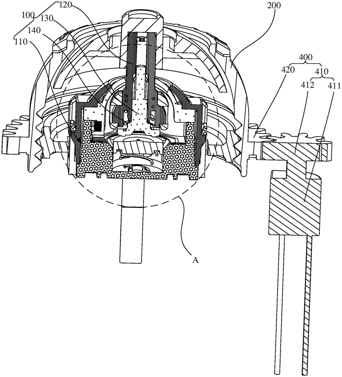
Referring toFIG.1toFIG.3, in one embodiment of the present application, the rocker mechanism includes a rocker assembly100, an adjusting cover200, an adjusting plate300and an electronic control assembly400. The rocker assembly100includes a rocker base110, a rocker body120, a damping adjuster130and a first spring140. The rocker body120is movably mounted on the rocker base110and is provided with a telescopic channel121extending along a length direction of the rocker body120. The damping adjuster130includes a sliding part131and a rotating part132connected to the sliding part131, and the sliding part131can slide through the telescopic channel121. The first spring140is sleeved on the sliding part131and is provided between the rotating part132and the rocker body120. The adjusting cover200is located outside the rocker base110. The adjusting plate300is movably connected to the rocker base110, the top in surface of the adjusting plate300is in contact with the surface of rotating part132, and the peripheral edge of the adjusting plate300is threaded with the adjusting cover200. The electronic control assembly400is connected to the adjusting cover200in a driving manner to drive the adjusting cover200to rotate, so as to drive the adjusting plate300to move closer to or away from the rocker body120.
It can be understood, when the rocker body120is in the center position, the rotating part132of the damping adjuster130is closer to the rocker body120. That is, the greater the initial compression of the first spring140, the greater the force that the user needs to apply when turning and tilting the rocker body120, and therefore the greater the damping. The farther the rotating part132of the damping adjuster130is from the rocker body120, that is, the smaller the initial compression of the first spring140, the smaller the force that the user needs to apply when turning and tilting the rocker body120. In this embodiment, by controlling the electronic control assembly400to drive the rotation of the adjusting cover200, the adjusting plate300is driven to move closer to or away from the rocker body120, thereby driving the rotating part132of the damping adjuster130to move closer to or away from the rocker body, adjusting the distance between the rotating part132of the damping adjuster130and the rocker body120, and achieving the purpose of adjusting the damping of the rocker body120in the rocker mechanism. This solution allows for the direct rotation of the adjusting cover200by the electronic control assembly400to achieve the adjustment of the damping of the rocker body120in the rocker mechanism. There is no need to disassemble the decorative shell of the outer layer of the rocker mechanism, functional parts that hinder the damping adjuster130, and other parts that interfere with the user's adjustment of the position of the damping adjuster130. In this way, the user can save the tedious steps of disassembling parts and manually adjusting the distance between the rotating part132of the damping adjuster130and the rocker body120, so as to quickly adjust the damping of the rocker body120of the rocker mechanism. It can be seen that the damping adjustment steps of the rocker body120in the rocker mechanism of the technical solution of the present application are simple, and the damping of the rocker body120of the rocker mechanism can be quickly adjusted, thereby increasing the user's sense of comfort.
In this embodiment, the sliding part131of the damping adjuster130is a sliding rod. The sliding rod extends into the telescopic channel121and slides with the inner wall of the telescopic channel121. When the user turns and tilts the rocker body120, there is a certain contact area between the rotating part132of the damping adjuster130and the adjusting plate300, causing the rotational fulcrum of the damping adjuster130and the rocker body120not located at the axis position shown in the figure. So the relative distance between the rotation part132of the damping adjuster130and the rocker body120becomes smaller. Therefore, the first spring140, which is in contact with the rocker body120and the rotating part132of the damping adjuster130, is compressed, causing the rocker body120to tend to return to center.
In one embodiment, an installation cavity is provided at one end of the rocker body120close to the rotating part132of the damping adjuster130. The first spring140is sleeved on the sliding part131and is at least partially received in the installation cavity. Both ends of the first spring140are respectively in contact with the rotating part132of the damping adjuster130and the rocker body120. In other embodiments, the rocker body120can be formed with a sliding rod, and the sliding part131of the damping adjuster130can be formed with a cavity that accommodates the sliding rod and is slidably matched with the sliding rod, thereby also achieving the effect of making the sliding part131and the rocker body120telescopically nested and slidingly matched.
In one embodiment, the electronic control assembly400includes a driving assembly410and a transmission part420provided on the peripheral surface of the adjusting cover200, the driving assembly410is connected to the transmission part420in a driving manner to drive the transmission part420to rotate. This electronic control assembly400has a simple structure, making it not only easy to process but also easy to install, thereby saving production costs.
In one embodiment, the transmission part420is configured as a first gear. This is because the transmission accuracy of the gear is high, which can improve the accuracy of the electronic control assembly400in controlling the distance between the rotating part132of the damping adjuster130and the rocker body120, thereby helping to improve the damping adjustment accuracy of the rocker body120of the rocker mechanism. Moreover, the gear works reliably and has a long life span, which can increase the life span of the electronic control assembly400. Of course, the present application is not limited to this. In another embodiments, the transmission part420can also be configured as a transmission wheel, and the driving assembly410includes a motor, a driving wheel of an output shaft provided on the motor, and a transmission belt. The driving wheel drives the transmission wheel to rotate through the transmission belt, thereby driving the adjusting cover200to rotate.
In one embodiment, the driving assembly410includes a rotating motor411and a second gear412provided on an output shaft of the rotating motor411, the transmission teeth of the first gear mesh with the transmission teeth of the second gear412. Such a driving assembly410has high transmission accuracy, which can improve the accuracy of the electronic control assembly400in controlling the distance between the rotating part132of the damping adjuster130and the rocker body120, thereby improving the damping adjustment accuracy of the rocker body120of the rocker mechanism.
It should be noted that the electronic control assembly400also includes a control key and a main control board, and the control key and the driving assembly410are electrically connected to the main control board respectively. When it needs to adjust the damping of the rocker body120of the rocker mechanism, the user can trigger the control key, and the control key sends information to the main control board. After receiving the information, the main control board sends a control command to the driving assembly410. After receiving the command, the driving assembly410drives the adjusting cover200to rotate, thereby driving the adjusting plate300to extend the thread pattern of the adjusting cover200to move closer to or away from the rocker body120. Then, the rotating part132of the damping adjuster130is pushed towards or away from the rocker body, thereby adjusting the distance between the rotating part132of the damping adjuster130and the rocker body120, and finally realizing the damping adjustment of the rocker body120of the rocker mechanism.
The control button can be configured as a touch button or a physical button. There is no specific restriction on the structural form of the control button, as long as it can send commands from the user.
It can be understood that the driving assembly410is electrically connected to the main control board, which means that the driving part of the driving assembly410is electrically connected to the main control board. The driving part is the power source. For example, when the driving assembly410includes a rotating motor411and a second gear412, the rotating motor411is electrically connected to the main control board, and when the driving assembly410includes a linear motor or a cylinder and a rack, the linear motor or cylinder is electrically connected to the main control board.
The diameter of the first gear is larger than the diameter of the second gear412. It can be understood that the first gear is the large gear, and the second gear412is the small gear. Using the small gear to drive the large gear can help in deceleration, which is beneficial for fine-tuning. Moreover, providing a large gear and a small gear facilitates controlling the exchange ratio of the driving part's motion path through the diameter and number of teeth. Of course, the present application is not limited thereto. In other embodiments, the diameter of the first gear may also be equal to the diameter of the second gear412.
In one embodiment, the driving assembly410includes a rotating motor411and a worm provided on an output shaft of the rotating motor411, the transmission teeth of the first gear mesh with the transmission teeth of the worm. In another embodiment, the driving assembly410includes a linear motor and a rack provided on an output shaft of the linear motor, and the transmission teeth of the rack mesh with the transmission teeth of the first gear. The user can select the appropriate driving assembly410according to the spatial arrangement of the rocker assembly100or their hands. The electronic control assembly400only needs to be able to drive the adjusting cover200to rotate. The specific composition of the electronic control assembly400is not limited here.
In one embodiment, the transmission part420and the adjusting cover200are integrally formed, which can increase the connection strength between the transmission part420and the adjusting cover200. Of course, the present application is not limited to this. In other embodiments, the transmission part420and the adjusting cover200can also be formed separately and then welded or bonded together.
Referring toFIG.3toFIG.7, in one embodiment, the rocker base110also includes a rocker shell111, the rocker body120is movably installed in the rocker shell111, and the wall of the rocker shell111is provided in a plurality of avoidance channels111a. The adjusting plate300includes a sustaining part310, a threaded part320provided outside the sustaining part310, and a plurality of penetration parts330connecting the sustaining part310and the threaded part320. One penetration part330is provided corresponding to one of the avoidance channels111a, and the penetration part330is movably penetrated in the avoidance channel111a. The sustaining part310is provided in the rocker shell111, and the top surface of the sustaining part310is in connect with the surface of the rotating portion132. The threaded part320is threaded to cooperate with the threads of the adjusting cover200. Such a structure can not only better protect the internal components of the rocker base110without interfering with the movement of the adjusting plate300, but also increase the life span of the rocker assembly100.
In one embodiment, the threaded part320is configured as an external thread provided on the peripheral surface of the adjusting plate300, and an internal thread is formed on the inner wall of the adjusting cover200corresponding to the external thread of the adjusting plate300. The external threads and internal threads cooperate, so that when the adjusting cover200rotates, the adjusting plate300can be driven to move towards or away from the rocker body120relative to the rocker shell111along the lines of the internal threads of the adjusting cover200. This drives the rotating part132of the damping adjuster130closer to or away from the rocker body120, so that when the rocker body120is in the center position, the initial compression amount of the first spring140changes, thereby adjusting the damping of the rocker body120.
It can be understood, when the rocker body120is in the center position, the rotating part132of the damping adjuster130is closer to the rocker body120. That is to say, the greater the initial compression of the first spring140, the greater the force that the user needs to apply when turning and tilting the rocker body120, and therefore the greater the damping. The farther the damping adjuster130is from the rocker body120, that is, the smaller the initial compression of the first spring140, the smaller the force that the user needs to apply when turning and tilting the rocker body120, and therefore the smaller the damping. In this way, the player can adjust the damping of the rocker body120according to his own preference by controlling the electronic control assembly400to drive the adjusting cover200. The steps for adjusting the damping of the rocker body120of such a rocker mechanism are simple, and the damping of the rocker body120of the rocker mechanism can be quickly adjusted.
Of course, in other embodiments, the inner wall of the adjusting cover200may be formed with a plurality of protrusions, and the adjusting plate300may be formed with a groove extending spirally along its outer circumference. The plurality of protrusions extend into the groove. The adjusting cover200is connected to the adjusting plate300through the matching of protrusions and grooves, which can also achieve the effect of driving the adjusting cover200to rotate through the electronic control assembly400, thereby driving the damping adjuster130to move and adjusting the damping of the rocker body120. Meanwhile, in other embodiments, the adjusting cover200may be formed with external threads on its outer wall, and the adjusting plate300may be formed with a cylindrical structure surrounding the outer wall of the adjusting cover200. The inner wall of the cylindrical structure is formed with internal threads corresponding to the external threads. So that, the adjusting cover200can also be rotatably connected to the adjusting plate300through a threaded structure.
In this embodiment, the number of turns of the internal thread of the adjusting cover200is greater than the number of turns of the external thread of the adjusting plate300, so as to achieve a larger adjustment range. Of course, the present application is not limited to this. The number of turns of the internal thread of the adjusting cover200and the number of turns of the external thread of the adjusting plate300can be adaptively adjusted according to actual adjustment requirements (such as thread pitch, adjustment range).
In this embodiment, although the rocker shell111includes an upper shell111band a lower shell111c, the present application is not limited thereto. The rocker shell111can be integrally formed by injection molding. The rocker shell111can be made of plastic or metal, and is used to be fixed on an input device such as a game controller and provide fixation and support for other components of the rocker assembly100.
In this embodiment, a plurality of limiting holes are also provided between the sustaining part310and the threaded part320of the adjusting plate300. The upper shell111band the lower shell111cof the rocker shell111are formed with a plurality of limiting columns corresponding to the limiting holes. The limiting column passes through the limiting hole to limit the rotation of the adjusting plate300relative to the rocker shell111, so that the adjusting plate300can only move within the rocker shell111.
In other embodiments, the rocker shell111can be formed with a limiting hole, and the adjusting plate300can be formed with a limiting column. In this case, the adjusting plate300can also be movably connected to the rocker shell111.
In one embodiment, the rocker assembly100also includes a second spring. Two ends of the second spring respectively are in contact with the lower surface of the adjusting plate300and the bottom of the rocker shell111, so as to support and balance the load of the adjusting plate300, so that the electronic control assembly400can rotate the adjusting cover200more smoothly and has a better feel of usage.
In order to maintain better structural stability, in this embodiment, the second spring is a conical coil spring. Of course, the present application is not limited to this. In other embodiments, the rocker assembly100may not include the second spring, and its basic damping adjustment effect can still be achieved.
In one embodiment, the rocker base110includes an upper rocker arm112, a lower rocker arm113, a first magnet114, a second magnet115, a pressing base116, a circuit board117, a metal dome118and a Hall integrated circuit, the upper rocker arm112and the lower rocker arm113are respectively rotatably installed in the rocker shell111and cover each other to form a rotation space inside, and a part of the rocker body120is limited to the rotation space and can be tilted and rotated by the user. The first magnet114is installed on the upper rocker arm112, the second magnet115is installed on the lower rocker arm113, and the pressing base116is connected to the lower rocker arm113. The circuit board117is provided below the pressing base116, and the metal dome118and the Hall integrated circuit are installed on the circuit board117. The pressing base116can be driven by the lower rocker arm113to press the metal dome118to achieve a click operation of the rocker. The first magnet114and the second magnet115are respectively coupled to the Hall integrated circuit on the circuit board117, so as to convert the rotation information of the upper rocker arm112and the lower rocker arm113into electrical signals and output them through the circuit board117. It is worth noting that detailed instructions on how to install and rotate the rocker assembly100and how to convert magnetic field changing information into electrical signals have been disclosed in detail in relevant patent documents, and it is also well known to those skilled in the art, so it will not be described here again.
In other embodiments, the rocker assembly100with a potentiometer can be used to replace the first magnet114, the second magnet115, the pressing base116, the circuit board117, the metal dome118and the Hall integrated circuit. In some special cases, the rocker assembly100may only include a rocker, an upper rocker arm112and a lower rocker arm113. In this case, the rocker assembly100may not output an electrical signal but only for testers to debug the usage feeling of the rocker assembly100. The above-mentioned situations are all included in the protection scope of the present application.
The present application further provides a game controller, including a controller shell and a rocker mechanism. The specific structure of the rocker mechanism refers to the above-mentioned embodiments. Since the game controller adopts all the technical solutions of the above embodiments, it has at least all the beneficial effects brought by the technical solutions of the above embodiments, which will not be described again here. The rocker mechanism is installed inside the controller shell.
The above are only some embodiments of the present application, and do not limit the scope of the present application. Under the concept of the present application, any equivalent structural transformations made by using the description and accompanying drawings of the present application, or direct/indirect application in other related technical fields, are included in the scope of the present application.
Claims
- A rocker mechanism, comprising: a rocker assembly, comprising a rocker base, a rocker body, a damping adjuster and a first spring, wherein the rocker body is movably provided on the rocker base and is provided with a telescopic channel extending along a length direction of the rocker body, the damping adjuster comprises a sliding part and a rotating part connected to the sliding part, the sliding part is configured to slide through the telescopic channel, and the first spring is sleeved on the sliding part and is provided between the rotating part and the rocker body;an adjusting cover, located outside the rocker base;an adjusting plate, movably connected to the rocker base, wherein a top surface of the adjusting plate is in contact with a surface of the rotating part, and a peripheral edge of the adjusting plate is threaded to cooperate with threads of the adjusting cover;and an electronic control assembly, connected to the adjusting cover in a driving manner to drive the adjusting cover to rotate, so as to drive the adjusting plate to move closer to or away from the rocker body.
- The rocker mechanism of claim 1, wherein the electronic control assembly comprises a driving assembly and a transmission part provided on a peripheral surface of the adjusting cover, and the driving assembly is connected to the transmission part in a driving manner to drive the transmission part to rotate.
- The rocker mechanism of claim 2, wherein the transmission part and the adjusting cover are integrally formed.
- The rocker mechanism of claim 2, wherein the transmission part is configured as a first gear.
- The rocker mechanism of claim 4, wherein the driving assembly comprises a rotating motor and a worm provided on an output shaft of the rotating motor, and transmission teeth of the first gear mesh with transmission teeth of the worm.
- The rocker mechanism of claim 4, wherein the driving assembly comprises a linear motor and a rack provided on an output shaft of the linear motor, and transmission teeth of the rack mesh with transmission teeth of the first gear.
- The rocker mechanism of claim 4, wherein the driving assembly comprises a rotating motor and a second gear provided on an output shaft of the rotating motor, and transmission teeth of the first gear mesh with transmission teeth of the second gear.
- The rocker mechanism of claim 7, wherein a diameter of the first gear is larger than a diameter of the second gear.
- The rocker mechanism of claim 1, wherein the rocker base comprises a rocker shell, the rocker body is movably installed in the rocker shell, and a wall of the rocker shell is provided in a plurality of avoidance channels;the adjusting plate comprises a sustaining part, a threaded part provided outside the sustaining part, and a plurality of penetration parts connecting the sustaining part and the threaded part;one penetration part is provided corresponding to one of the avoidance channels, and the penetration part is movably penetrated in the avoidance channel;the sustaining part is provided in the rocker shell, and a top surface of the sustaining part is in connect with a surface of the rotating portion;and the threaded part is threaded to cooperate with threads of the adjusting cover.
- The rocker mechanism of claim 9, wherein the rocker base comprises an upper rocker arm, a lower rocker arm, a first magnet, a second magnet, a pressing base, a circuit board, a metal dome and a Hall integrated circuit, the upper rocker arm and the lower rocker arm are respectively rotatably installed in the rocker shell and cover each other to form a rotation space inside, and a part of the rocker body is limited to the rotation space;the first magnet is installed on the upper rocker arm, the second magnet is installed on the lower rocker arm, and the pressing base is connected to the lower rocker arm;and the circuit board is provided below the pressing base, and the metal dome and the Hall integrated circuit are installed on the circuit board.
- A game controller, comprising: a controller shell;and the rocker mechanism of claim 1, wherein the rocker mechanism is installed inside the controller shell.
Disclaimer: Data collected from the USPTO and may be malformed, incomplete, and/or otherwise inaccurate.