U.S. Pat. No. 12,290,746
MOBILE GAME CONTROLLER AND FULL FEATURE GAME CONTROLLER COMBINATION DEVICE
AssigneeACCO BRANDS CORPORATION
Issue DateSeptember 6, 2022
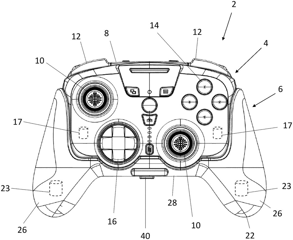
Illustrative Figure
Abstract
A device may include a first unit and a second unit. The first unit may include a first body that has a controller interface that is operatively connected to one or more processors disposed in the first body and configured to operatively connect to a gaming device. The first body may include one or more rumble motors to provide haptic feedback to a user in response to the gaming device. A first communication port may be operatively mounted to the first body and operatively connected to the one or more processors. The second unit may include a second body separate from the first body, one or more second rumble motors operatively installed to the second body, and a second communication port configured to communicatively connect to the first communication port such that the one or more processors effectively controls the one or more second rumble motors.
Description
DETAILED DESCRIPTION FIGS.1-4illustrate an exemplary mobile game controller and full feature game controller combination device2comprising a first unit4and a second unit6. When in a combined configuration (as shown inFIG.1) the combination device2may act as an at home full feature game controller. However, when the first unit4is separated from the second unit6(as shown inFIG.2), the first unit4may act as a mobile video game controller. The first unit4includes a first body8. Operatively installed to the first body8may be at least one analog stick10, at least two trigger buttons12(which may include shoulder trigger inputs12aand lower trigger inputs12b), at least one action button14, and at least one directional pad16. The analog stick10, trigger buttons12, action button14, and directional pad16of the first unit4may serve as a first control interface between the controller's user and a desired video game. Furthermore, the control interface of the first unit4may include one or more first rumble motors17(shown ghosted inFIG.1) or other haptic feedback device disposed within the first body8. In the embodiments depicted in the exemplary device inFIGS.1-4the control interface of the first body8includes two analog sticks10, two trigger buttons12, a plurality of action buttons14, and one directional pad16. In other embodiments, the control interface may include other types of control devices (e.g., track ball, voice controller, etc.) or may include different combinations of the control devices disclosed herein and other types of control devices. The control interface may be mapped and reprogramed to control the video game as desired. The first unit4may also include a processor702(shown inFIG.7) disposed within the first body8. The processor702may be implemented as one or more processors. The processor702may be operatively connected to a gaming device (e.g., a video game console, personal computer, laptop, mobile device, tablet, Smart TV, streaming device, etc.) and the control interface (including analog stick10, trigger buttons12, action button14, directional ...
DETAILED DESCRIPTION
FIGS.1-4illustrate an exemplary mobile game controller and full feature game controller combination device2comprising a first unit4and a second unit6. When in a combined configuration (as shown inFIG.1) the combination device2may act as an at home full feature game controller. However, when the first unit4is separated from the second unit6(as shown inFIG.2), the first unit4may act as a mobile video game controller.
The first unit4includes a first body8. Operatively installed to the first body8may be at least one analog stick10, at least two trigger buttons12(which may include shoulder trigger inputs12aand lower trigger inputs12b), at least one action button14, and at least one directional pad16. The analog stick10, trigger buttons12, action button14, and directional pad16of the first unit4may serve as a first control interface between the controller's user and a desired video game. Furthermore, the control interface of the first unit4may include one or more first rumble motors17(shown ghosted inFIG.1) or other haptic feedback device disposed within the first body8. In the embodiments depicted in the exemplary device inFIGS.1-4the control interface of the first body8includes two analog sticks10, two trigger buttons12, a plurality of action buttons14, and one directional pad16. In other embodiments, the control interface may include other types of control devices (e.g., track ball, voice controller, etc.) or may include different combinations of the control devices disclosed herein and other types of control devices. The control interface may be mapped and reprogramed to control the video game as desired.
The first unit4may also include a processor702(shown inFIG.7) disposed within the first body8. The processor702may be implemented as one or more processors. The processor702may be operatively connected to a gaming device (e.g., a video game console, personal computer, laptop, mobile device, tablet, Smart TV, streaming device, etc.) and the control interface (including analog stick10, trigger buttons12, action button14, directional pad16, rumble motors17, etc.) to receive user input and output user feedback. The processor702may communicate with the gaming device via a wired (input port62) or a wireless connection. The control interface may receive user input and transmit it to the processor702which communicates with the gaming device to control a video game. The processor702may receive video game feedback from the gaming device and may cause the one or more rumble motors17to vibrate to provide haptic feedback to the user.
The first unit4may also include a first communication port20operatively mounted to the first body8. The first communication port20may be operatively connected to the processor702. In the illustrated embodiment, the communication port20is disposed on the bottom surface of the first body8. In other embodiments, the communication port20may be disposed on other surfaces of the first body8such as the backside or sides of the first body8. In other embodiments, the communication port20may be a wireless communication port.
The second unit6includes a second body22. The second body22is separate form the first body8. The second unit6may include one or more second rumble motors23(shown ghosted inFIG.1) operatively installed to and disposed within the second body22. The second unit6may also include one or more advance gaming buttons30. The advance gaming buttons30may be disposed along the second body22. The second body22may further include a second communication port24that is operatively mounted to the second body22. The second communication port24may be configured to communicatively connect to the first communication port20such that the processor702effectively controls the one or more second rumble motors23to vibrate to provide haptic feedback to the user and the advance gaming buttons30to provide additional user inputs. Thus, the rumble motors23, the advance gaming buttons30and any other control device of the second unit6may serve as a second control interface between the user of the controller2and a desired video game when the second unit6is connected to the first unit4.
The first and second communication ports20,24may be comprised of a first and second electrical connector, such as, for example, a plug and socket electrical connector, as shown, configured to connect to each other. However, it is to be appreciated that any suitable electrical connector may be utilized. In other embodiments, the first and second communication ports20,24may include first and second wireless communication devices. The first and second wireless communication devices may be comprised of Wi-Fi, Bluetooth, Infrared wireless connection, induction wireless connection, or any other suitable wireless communication devices. In those embodiments, the second wireless communication device is configured to wirelessly connect to the first wireless communication device.
In an embodiment the first unit4may be configured such that, when operated by itself, it operates as a mobile video game controller. The first body8of the first unit4may be configured such that it has a substantially rectangular shape that is relatively compact so that the first unit4may be easily stored and transported. The first body8may be shaped in other suitable configurations such as ovular, circular, or triangular, etc. as long as it remains relatively compact.
The second body22of the second unit6may resemble a grip portion of a conventional video game controller such that, when the second body22is installed to the first body8, the resulting device2has an ergonomically correct shape to accommodate the hands of a user. The second body22may, for example, have two extending handhold members or wings26. The wings26may be connected to one another via a central potion28. The central portion28may have a cavity that is complementary to the first body8to receive the first body8and allow the second body22to couple to the first body8. When the first body8is coupled to the second body22such that it is fully received with the central portion28, the combination controller device2resembles a full featured game controller.
In one embodiment, the first body8may removably engage and connect to the second body22by a mechanical retaining structure. For example, the mechanical retaining structure may include at least one tongue32disposed within the central portion28of the second body22. The at least one tongue32may be disposed on an interior surface of the central portion28. The at least one tongue32is configured to engage an at least one receiving groove or slot34in the first body8. The at least one receiving groove34may be disposed on a side wall of the first body8. However, at least one receiving groove34may be disposed anywhere along the first body8so long as it corresponds with the at least one tongue32of the second body22. Other suitable mechanical retaining structures are possible. The combination device2may include a securing mechanism or lock40to ensure the first body8does not accidentally disengage from the second body22. For example, the securing mechanism40may be a slide lock comprised of a slidable engagement feature protruding portion44disposed in the second body22and a slidable engagement feature receiving portion46in the first body8. The engagement feature may be engaged and disengaged by sliding it to a locked position and to an unlocked position. Any other suitable means of locking may be used for securing the first body8to the second body22.
Coupling the first communication port20to the second communication 24 port may configure the processor702to effectively control the one or more second rumble motors23. In one embodiment, coupling the first communication port20to the second communication 24 port configures the processor702to control the second rumble motors23instead of or in addition to the first rumble motors17to provide haptic feedback to the user at a higher intensity and/or lower frequency compared to an intensity and/or frequency provided to the user by the mobile video game controller4alone. In an embodiment, when the first body8and second body22are coupled together via the first communication port20and second communication port24, the processor702communicates with the first unit4and second unit6to cease operating (e.g., turn off) the one or more first rumble motors17in the first body8and begin operating (e.g., turn on) the one or more second rumble motors23in the second body22. In another embodiment, when the first body8and second body22are coupled together via the first and second communication port20,24, the connection causes the processor702to initiate control of the one or more second rumble motors23and to continue operation of the one or more first rumble motors17.
In another embodiment, the first unit4may include a microphone configured on the first body8. The microphone may communicate with the processor to relay audio inputs to a video game.
In another embodiment, the first unit4may include an audio input/output port50disposed along the bottom side of the first body8to receive a wired headphone or headphone/microphone combination connection. For example, the audio input/output port50may be a 3.5-millimeter (mm) audio input jack or other suitable input/output port for a wired audio connection. The second unit6may also include an aperture52disposed along the bottom side of the second body22such that its location corresponds with the location of the audio input/output port50of the first body8so the port50may be accessed.
In another embodiment, the first unit4may include a first power supply60disposed in the first body8. The first power supply60may include, for example, a rechargeable battery, or any other suitable means for providing power to the first unit4. Furthermore, when the first unit4and second unit6are coupled together to form the full feature combination device2, the first power supply60may power the second unit6. The first body8may include a charging input62to charge the batteries of the first power supply60. The charging input62, for example, may be any suitable means of charging such as USB-C, micro-USB, etc. The charging input62may power the first device2when connected to an external power supply by a charging cable. The input62may additionally serve as the wired interface between the device2and the gaming device (e.g., console, PC, etc.) Furthermore, the first body8may include an indicator light64for indicating that the first power supply60is charging. In another embodiment, the second unit6may include a second power supply. In one embodiment, the second power supply may provide a backup power supply to the first power supply60.
In the embodiment ofFIG.5, the video game controller device2includes a mobile device clip120that includes a clamp122for securing a mobile device (e.g., smart phone, tablet, etc.) to the device2. The mobile device clip120may include rotational elements124such that a user may adjust the orientation of the mobile device mounted to the clip120. The mobile device clip120may be configured such that it is removably attached from the device2.
Exemplary methods may be better appreciated with reference to the flow diagram ofFIG.6. While for purposes of simplicity of explanation, the illustrated methodologies are shown and described as a series of blocks, it is to be appreciated that the methodologies are not limited by the order of the blocks, as some blocks can occur in different orders or concurrently with other blocks from that shown and described. Moreover, less than all the illustrated blocks may be required to implement an exemplary methodology. Furthermore, additional methodologies, alternative methodologies, or both can employ additional blocks, not illustrated.
In the flow diagrams, blocks denote “processing blocks” that may be implemented with logic. The processing blocks may represent a method step or an apparatus element for performing the method step. The flow diagrams do not depict syntax for any particular programming language, methodology, or style (e.g., procedural, object-oriented). Rather, the flow diagrams illustrate functional information one skilled in the art may employ to develop logic to perform the illustrated processing. It will be appreciated that in some examples, program elements like temporary variables, routine loops, and so on, are not shown. It will be further appreciated that electronic and software applications may involve dynamic and flexible processes so that the illustrated blocks can be performed in other sequences that are different from those shown or that blocks may be combined or separated into multiple components. It will be appreciated that the processes may be implemented using various programming approaches like machine language, procedural, object oriented or artificial intelligence techniques.
FIG.6illustrates a flow diagram for an exemplary method200for controlling a video game. At210, the method200may include interfacing a mobile video game controller to a video game device. At220, the method200includes receiving user video game control instructions from a first video game control user interface including one or more of a) an analog stick, b) a trigger button, c) an action button, and d) a directional pad. At230, the method200includes communicating computer video game control instructions corresponding to the user video game control interface to the video game device. At240, the method200includes receiving video game feedback and causing one or more first rumble motors to vibrate based on the video game feedback to provide haptic feedback to the user. At250, the method200includes interfacing the mobile video game controller to a complementary unit to form an enhanced video game controller. At260, the method200includes receiving video game feedback and causing one or more second rumble motors to vibrate based on the video game feedback to provide enhanced haptic feedback to the user at a higher intensity and/or lower frequency compared to an intensity and/or frequency provided to the user by the mobile video game controller alone.
In one embodiment, interfacing the mobile video game controller to the complementary unit results in the enhanced video game controller being ergonomically correct to accommodate hands of a user.
In one embodiment, interfacing the mobile video game controller to the complementary unit includes mechanically coupling the mobile video game controller and the complementary unit.
In one embodiment, interfacing the mobile video game controller to the complementary unit further includes mechanically and data communicatively coupling the mobile video game controller and the complementary unit resulting in the enhanced video game controller being ergonomically correct to accommodate hands of a user and the user receiving the enhanced haptic feedback.
In one embodiment, interfacing the mobile video game controller to the complementary unit further includes making an electrical connection between the mobile video game controller and the complementary unit.
In one embodiment, interfacing the mobile video game controller to the complementary unit includes making a wireless connection between the mobile video game controller and the complementary unit.
In one embodiment, interfacing the mobile video game controller to the complementary unit initiates control of the one or more second rumble motors.
FIG.7illustrates a block diagram of an exemplary full feature game controller combination device2. The device2includes a processor702, a memory704, the port20, and a storage712operably connected by a bus708.
In one example, the device2may transmit input and output signals as described above via, for example, ports20,24. The device2may also communicate with a gaming device via I/O Ports714. The device2may receive user input via the analog stick10, trigger buttons12, action buttons14, directional pad16, advance gaming buttons30, etc. and transmit user input signals to the gaming device via the I/O Ports714. Similarly, the device2may receive user feedback signals from the gaming device via I/O Ports714and transmit user feedback via the rumble motors17and23.
The processor702can be a variety of various processors including dual microprocessor and other multi-processor architectures. The memory704can include volatile memory or non-volatile memory. The non-volatile memory can include, but is not limited to, ROM, PROM, EPROM, EEPROM, and the like. Volatile memory can include, for example, RAM, synchronous RAM (SRAM), dynamic RAM (DRAM), synchronous DRAM (SDRAM), double data rate SDRAM (DDR SDRAM), and direct RAM bus RAM (DRRAM). The storage712may be operably connected to the processor702via the bus708. The storage712can include, but is not limited to, devices like a magnetic disk drive, a solid-state disk drive, a flash memory card, or a memory stick. The memory704can store processes or data. The storage712or memory704can store an operating system that controls and allocates resources of the device2.
The bus708can be a single internal bus interconnect architecture or other bus or mesh architectures. While a single bus is illustrated, it is to be appreciated that device2may communicate with various devices, logics, and peripherals using other busses that are not illustrated (e.g., PCIE, SATA, Infiniband, 1394, USB, Ethernet). The bus708can be of a variety of types including, but not limited to, a memory bus or memory controller, a peripheral bus or external bus, a crossbar switch, or a local bus. The local bus can be of varieties including, but not limited to, an industrial standard architecture (ISA) bus, a microchannel architecture (MCA) bus, an extended ISA (EISA) bus, a peripheral component interconnect (PCI) bus, a universal serial (USB) bus, and a small computer systems interface (SCSI) bus.
The device2may interact with input/output devices via I/O Ports714. Input/output devices can include, but are not limited to, a keyboard, a microphone, a pointing and selection device, cameras, video cards, displays, gaming devices, and the like. The I/O Ports714can include but are not limited to, serial ports, parallel ports, and USB ports. The device2can operate in a network environment and thus may be connected to network devices via the I/O Ports714. Through the I/O Ports714, the device2may interact with a network. Through the network, the device2may be logically connected to remote devices. The networks with which the device2may interact include, but are not limited to, a local area network (LAN), a wide area network (WAN), and other networks. The I/O Ports714can connect to LAN technologies including, but not limited to, fiber distributed data interface (FDDI), copper distributed data interface (CDDI), Ethernet (IEEE 802.3), token ring (IEEE 802.5), wireless computer communication (IEEE 802.11), Bluetooth (IEEE 802.15.1), Zigbee (IEEE 802.15.4) and the like. Similarly, the I/O Ports714can connect to WAN technologies including, but not limited to, point to point links, circuit switching networks like integrated services digital networks (ISDN), packet switching networks, and digital subscriber lines (DSL). While individual network types are described, it is to be appreciated that communications via, over, or through a network may include combinations and mixtures of communications.
DEFINITIONS
The following includes definitions of selected terms employed herein. The definitions include various examples or forms of components that fall within the scope of a term and that may be used for implementation. The examples are not intended to be limiting. Both singular and plural forms of terms may be within the definitions.
An “operable connection,” or a connection by which entities are “operably connected,” is one in which signals, physical communications, or logical communications may be sent or received. Typically, an operable connection includes a physical interface, an electrical interface, or a data interface, but it is to be noted that an operable connection may include differing combinations of these or other types of connections sufficient to allow operable control. For example, two entities can be operably connected by being able to communicate signals to each other directly or through one or more intermediate entities like a processor, operating system, a logic, software, or other entity. Logical or physical communication channels can be used to create an operable connection.
To the extent that the term “includes” or “including” is employed in the detailed description or the claims, it is intended to be inclusive in a manner similar to the term “comprising” as that term is interpreted when employed as a transitional word in a claim. Furthermore, to the extent that the term “or” is employed in the detailed description or claims (e.g., A or B) it is intended to mean “A or B or both.” When the applicants intend to indicate “only A or B but not both” then the term “only A or B but not both” will be employed. Thus, use of the term “or” herein is the inclusive, and not the exclusive use. See, Bryan A. Garner, A Dictionary of Modern Legal Usage624(2d. Ed. 1995).
While example systems, methods, and so on, have been illustrated by describing examples, and while the examples have been described in considerable detail, it is not the intention of the applicants to restrict or in any way limit scope to such detail. It is, of course, not possible to describe every conceivable combination of components or methodologies for purposes of describing the systems, methods, and so on, described herein. Additional advantages and modifications will readily appear to those skilled in the art. Therefore, the invention is not limited to the specific details, the representative apparatus, and illustrative examples shown and described. Thus, this application is intended to embrace alterations, modifications, and variations that fall within the scope of the appended claims. Furthermore, the preceding description is not meant to limit the scope of the invention. Rather, the scope of the invention is to be determined by the appended claims and their equivalents.
Claims
- A mobile game controller and full feature game controller combination device, comprising: a first unit including: a first body, at least one analog stick, at least two trigger buttons, at least one action button, at least one directional pad, and one or more first rumble motors operatively installed to the first body, one or more processors disposed in the first body and configured to operatively connect to a gaming device and operatively connected to the at least one analog stick, the at least two trigger buttons, the at least one action button, the at least one directional pad, and the one or more rumble motors to receive user input via the at least one analog stick, the at least two trigger buttons, the at least one directional pad, and the at least one action button and control a video game executed by the gaming device and to receive video game feedback and cause the one or more rumble motors to vibrate to provide haptic feedback to the user, and a first communication port operatively mounted to the first body and operatively connected to the one or more processors;a second unit including: a second body separate from the first body, wherein the second body has a shape complementary of a shape of the first body for coupling of the second body to the first body one or more second rumble motors operatively installed to the second body, and a second communication port operatively mounted to the second body and configured to communicatively connect to the first communication port such that the one or more processors effectively controls the one or more second rumble motors to vibrate to provide enhanced haptic feedback to the user.
- The mobile game controller and full feature game controller combination device of claim 1, wherein the second body has an ergonomically correct shape to accommodate hands of a user.
- The mobile game controller and full feature game controller combination device of claim 1, wherein the second body has a shape complementary of a shape of the first body such that coupling of the second body to the first body resembles a full feature game controller.
- The mobile game controller and full feature game controller combination device of claim 1, wherein the first body has a substantially rectangular shape and the second body has an ergonomically correct shape to accommodate hands of a user, wherein the second body has a shape complementary of the shape of the first body such that coupling of the second body to the first body resembles a full feature game controller.
- The mobile game controller and full feature game controller combination device of claim 1, wherein the first communication port includes a first electrical connector and the second communication port includes a second electrical connector configured to connect to the first electrical connector.
- The mobile game controller and full feature game controller combination device of claim 1, wherein the first communication port includes a first wireless communication device and the second communication port includes a second wireless communication device configured to wirelessly connect to the first wireless communication device.
- The mobile game controller and full feature game controller combination device of claim 1, wherein coupling the first communication port to the second communication port configures the one or more processors to effectively control the one or more second rumble motors to vibrate and coupling the first body to the second body configures the one or more second rumble motors to provide haptic feedback to the user at a higher intensity and/or lower frequency compared to an intensity and/or frequency provided to the user by the one or more first rumble motors alone.
- The mobile game controller and full feature game controller combination device of claim 1, wherein coupling the first body to the second body causes the one or more processors to initiate control of the one or more second rumble motors and to cease operation of the one or more first rumble motors.
- The mobile game controller and full feature game controller combination device of claim 1, wherein coupling the first body to the second body causes the one or more processors to initiate control of the one or more second rumble motors and to continue operation of the one or more first rumble motors.
- A video game controller kit, comprising: a mobile video game controller including: a first body, a first video game control user interface including one or more of a) an analog stick, b) a trigger button, c) an action button, and d) a directional pad and one or more first rumble motors operatively installed to the first body, one or more processors disposed in the first body and configured to operatively connect to a gaming device and operatively connected to the first video game control user interface to receive user input and control a video game executed by the gaming device and to receive video game feedback and cause the one or more first rumble motors to vibrate to provide haptic feedback to the user, and a first communication port operatively mounted to the first body and operatively connected to the one or more processors;a complementary unit including: a second body separate from the first body, wherein the second body has a shape complementary of a shape of the first body for coupling of the second body to the first body, a second video game user interface including one or more second rumble motors operatively installed to the second body, and a second communication port operatively mounted to the second body and configured to communicatively connect to the first communication port such that the one or more processors effectively controls the second video game user interface including causing the one or more second rumble motors to vibrate to provide enhanced haptic feedback to the user.
- The video game controller kit of claim 10, wherein the second body has an ergonomically correct shape to accommodate hands of a user.
- The video game controller kit of claim 10, wherein the second body has a shape complementary of a shape of the first body to accommodate coupling of the second body to the first body.
- The video game controller kit of claim 10, wherein the first body has a substantially rectangular shape and the second body has an ergonomically correct shape to accommodate hands of a user, wherein the second body is configured to couple to the first body.
- The video game controller kit of claim 10, wherein the first communication port includes a first electrical connector and the second communication port includes a second electrical connector configured to connect to the first electrical connector.
- The video game controller kit of claim 10, wherein the first communication port includes a first wireless communication device and the second communication port includes a second wireless communication device configured to wirelessly connect to the first wireless communication device.
- The video game controller kit of claim 10, wherein coupling the first communication port to the second communication port configures the one or more processors to effectively control the one or more second rumble motors to vibrate and coupling the first body to the second body configures the kit to provide haptic feedback to the user at a higher intensity and/or lower frequency compared to an intensity and/or frequency provided to the user by the mobile video game controller alone.
- The video game controller kit of claim 10, wherein coupling the first body to the second body causes the one or more processors to initiate control of the one or more second rumble motors and to cease operation of the one or more first rumble motors.
- The video game controller kit of claim 10, wherein coupling the first body to the second body causes the one or more processors to initiate control of the one or more second rumble motors and to continue operation of the one or more first rumble motors.
- A video game controller set, comprising: a video game controller including: a first body, a first video game control user interface including one or more first user input devices and one or more first user output devices operatively installed to the first body, one or more processors disposed in the first body and configured to operatively connect to a gaming device and operatively connected to the first video game control user interface to receive user input via the one or more first user input devices to control a video game executed by the gaming device and to receive a feedback signal to cause the one or more first user output devices to provide feedback to the user, and a first communication port operatively mounted to the first body and operatively connected to the one or more processors;a complementary video game controller unit including: a second body separate from the first body, wherein the second body has a shape complementary of a shape of the first body for coupling of the second body to the first body, a second video game control user interface installed to the second body and including at least one or more of: one or more second user input devices, one or more second user output devices, a second communication port operatively mounted to the second body and configured to communicatively connect to the first communication port such that the one or more processors effectively controls the second video game control user interface to at least one of (a) receive user input via the one or more second user input devices to control the video game executed by the gaming device, and (b) receive video game feedback to cause the one or more second user output devices to provide enhanced feedback to the user.
- The video game controller set of claim 19, wherein the second body has an ergonomically correct shape complementary of a shape of the first body such that coupling of the first body and the second body results in an ergonomically correct set to accommodate hands of a user.
- The video game controller set of claim 19, wherein the one or more second user input devices of the second video game control user interface include one or more advanced gaming buttons.
- The video game controller set of claim 19, wherein the one or more second user output devices of the second video game control user interface include one or more rumble motors.
- The video game controller set of claim 19, wherein the second video game control user interface includes both one or more second user input devices and one or more second user output devices, wherein the one or more second user input devices include one or more advanced gaming buttons and the one or more second user output devices include one or more rumble motors.
Disclaimer: Data collected from the USPTO and may be malformed, incomplete, and/or otherwise inaccurate.