U.S. Pat. No. 12,285,676
Dynamically Changing Button Indicia for a Game Controller
AssigneeBackbone Labs, Inc.
Issue DateJune 5, 2024
Illustrative Figure
Abstract
A gaming device that includes a handheld controller having a handle and a depressible button on the handle configured to receive user input. The depressible button includes a first marking layer including a first indicia, a first light source configured to illuminate the first indicia in the first marking layer, a second marking layer stacked with the first marking layer and including a second indicia, and a second light source configured to illuminate the second indicia in the second marking layer.
Description
DETAILED DESCRIPTION As described herein, aspects are directed to dynamically changing button indicia for gaming input devices. Configurations of the disclosure include buttons that utilize multiple sources of light and a layered button structure to illuminate different indicia and thus display different indicia at the surface of the button. Accordingly, configurations of the disclosure limit the clutter of permanent markings on gaming input devices, limit confusion for users, and allow for flexibility between modes of gameplay or button function for various games. FIG.1depicts a front view of an example gaming input device101that may be used in configurations of the disclosed technology. As illustrated inFIG.1, the gaming input device101interfaces with a mobile device103, and the gaming input device101may be capable of replicating the console controller experiences of consoles like XBOX™ and PlayStation™ or otherwise serving as an input device for a variety of games to be played on the mobile device103. For purposes of the disclosure, “mobile device” refers to a portable, handheld computing device, such as a smartphone, tablet, or other comparable mobile device. The gaming input device101may be, for example, the game controller for a mobile device as disclosed in patent U.S. Pat. No. 11,389,721. As illustrated inFIG.1, the game controller101includes handles104. Each handle104in the example configuration includes user-accessible, hardware interfaces105, such as one or more of a button, an analog stick, a touchscreen, a touchpad, a knob, a slider, a switch, a wheel, a dial, a directional pad, or another such feature configured to accept touch inputs from a user's finger or a stylus. One or more of the user-accessible, hardware interfaces105may be dynamically changing buttons100, as described more fully below. FIG.2depicts a front view of another example gaming input device102that may be used in configurations of the disclosed technology. As with the gaming input device101ofFIG.1, the gaming ...
DETAILED DESCRIPTION
As described herein, aspects are directed to dynamically changing button indicia for gaming input devices. Configurations of the disclosure include buttons that utilize multiple sources of light and a layered button structure to illuminate different indicia and thus display different indicia at the surface of the button. Accordingly, configurations of the disclosure limit the clutter of permanent markings on gaming input devices, limit confusion for users, and allow for flexibility between modes of gameplay or button function for various games.
FIG.1depicts a front view of an example gaming input device101that may be used in configurations of the disclosed technology. As illustrated inFIG.1, the gaming input device101interfaces with a mobile device103, and the gaming input device101may be capable of replicating the console controller experiences of consoles like XBOX™ and PlayStation™ or otherwise serving as an input device for a variety of games to be played on the mobile device103. For purposes of the disclosure, “mobile device” refers to a portable, handheld computing device, such as a smartphone, tablet, or other comparable mobile device. The gaming input device101may be, for example, the game controller for a mobile device as disclosed in patent U.S. Pat. No. 11,389,721. As illustrated inFIG.1, the game controller101includes handles104. Each handle104in the example configuration includes user-accessible, hardware interfaces105, such as one or more of a button, an analog stick, a touchscreen, a touchpad, a knob, a slider, a switch, a wheel, a dial, a directional pad, or another such feature configured to accept touch inputs from a user's finger or a stylus. One or more of the user-accessible, hardware interfaces105may be dynamically changing buttons100, as described more fully below.
FIG.2depicts a front view of another example gaming input device102that may be used in configurations of the disclosed technology. As with the gaming input device101ofFIG.1, the gaming input device102ofFIG.2may be capable of replicating the console controller experiences of consoles like XBOX™ and PlayStation™ or otherwise serving as an input device for a variety of games to be played on the gaming input device102. As illustrated inFIG.2, the gaming input device102includes a display screen106integrated into a handheld game controller107and does not require interfacing with a user's mobile device103. The gaming input device102further includes handles104. Each handle104in the example configuration includes user-accessible, hardware interfaces105, such as one or more of a button, an analog stick, a touchscreen, a touchpad, a knob, a slider, a switch, a wheel, a dial, a directional pad, or another such feature configured to accept touch inputs from a user's finger or a stylus. One or more of the user-accessible, hardware interfaces105may be dynamically changing buttons100, as described more fully below.
For purposes of the discussion that follows, references to a gaming input device could refer to the gaming input device101ofFIG.1, the gaming input device102ofFIG.2, or any other gaming input device having physical buttons. Also, as used in this disclosure, “indicia” means the shapes, symbols, letters, or other markings on a button and that designate the button's function.
FIG.3is a detail view of a handle104of a gaming input device. As illustrated inFIG.3, the handle104may include one or more dynamically changing buttons100. The dynamically changing buttons100display different indicia108to match the appropriate gameplay environment. For example, as illustrated inFIG.4, the dynamically changing buttons100may follow a first configuration and display indicia108associated with those on XBOX™ controllers, without displaying other indicia. In addition, as illustrated inFIG.5, the same dynamically changing buttons100may instead follow a second configuration and display indicia108associated with those on PlayStation™ controllers. The references to indicia associated with those on XBOX™ controllers and to indicia associated with those on XBOX™ controllers are used as examples only, as they would be familiar to most game players. The indicia108, however, are not limited to those configurations and could include any indicia necessary or useful for gameplay or other activities with the gaming input device.
In configurations, when the gaming input device is not in use, or when a mode of use has not been selected, the dynamically changing buttons100appear blank or dark, as illustrated inFIG.3, because they are not internally illuminated in this third configuration. As discussed in further detail below, the dynamically changing buttons100thus display a dark background without visible indicia108.
In configurations, each of the dynamically changing buttons100is controlled individually. In such versions, then, the buttons100do not need to all be in the same configuration. Hence, for example, some buttons100could be in the first configuration, some could be in the second configuration, and some could be in the third configuration. In other configurations, all of the dynamically changing buttons100are in the same configuration.
Accordingly, in versions, the gaming input device may have dynamically changing buttons100that are configured to change between an “off” configuration in which the dynamically changing buttons100are not internally illuminated and at least one “on” configuration in which the dynamically changing buttons100are internally illuminated. In some example versions, there may be only one marking layer, such as the first marking layer110, and one light source, such as the first light source112. In other example versions, there may be more than one marking layer, such as the first marking layer110and the second marking layer113, and more than one light source, such as the first light source112and the second light source115. In other example versions, the gaming input device may have dynamically changing buttons100that are configured to change between at least two different “on” configurations in which the dynamically changing buttons100are internally illuminated, in which the “on” configurations are different because different indicia108are illuminated or because one or more of the indicia108that are illuminated in one of the “on” configurations is not illuminated in the other “on” configuration. These example versions may or may not include the top casing109(described below) in all versions of such configurations. Also, the dynamically changing buttons100may be controlled individually or all together in these example versions.
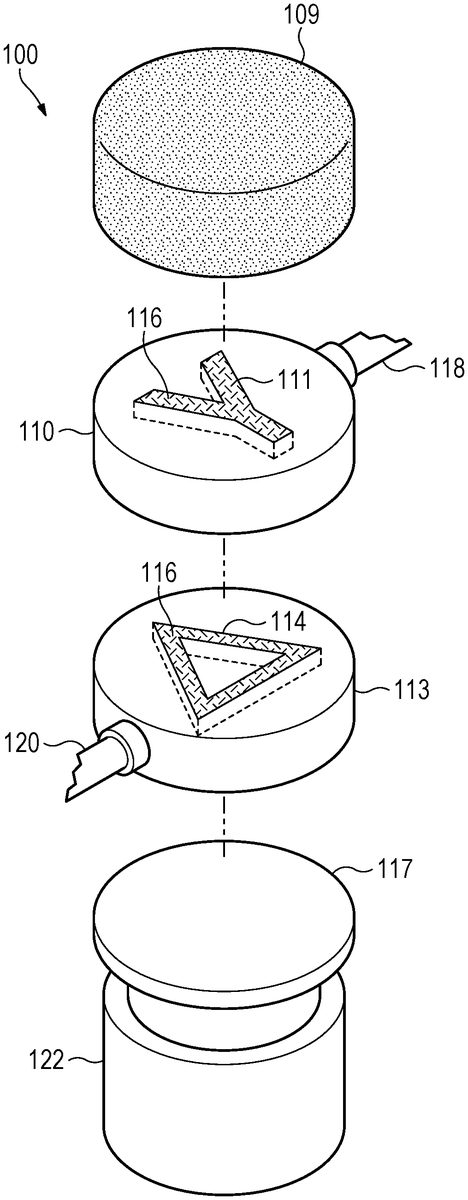
FIG.6depicts an example of a layered structure for the dynamically changing buttons100, according to example configurations.FIG.7is a perspective view of the dynamically changing button ofFIG.6, andFIG.8is an exploded view of the dynamically changing button ofFIG.7. As illustrated inFIGS.6-8, the dynamically changing buttons100may include a top casing109. The top casing109is semi-transparent and may be tinted to give the dynamically changing buttons100a dark, smoky appearance when the indicia108are not internally illuminated, while allowing light to pass through and display the indicia108when the indicia108are internally illuminated. In the illustrated configuration, below the top casing109is a first marking layer110with a first indicia111. The first marking layer110receives light from a first light source112, as described further below, illuminating the first indicia111and allowing the first indicia111to be displayed through the top casing109and thus displayed to the user. In the illustrated configuration, below the first marking layer110is a second marking layer113, which includes a second indicia114. The second marking layer113receives light from a second light source115, which is separate from the first light source112.
In versions, the first light source112and the second light source115may emit light that is colored, meaning that the emitted light is not white.
The first marking layer110and the second marking layer113are transparent, allowing light to shine through, but each is tinted with a color corresponding to its respective light source. In other words, the tinting is substantially the same color as the light emitted from the respective light source. As used in this context, “substantially the same color” means that the two colors are closely situated to each other in a defined color space. An example of a standard color space is the Adobe RGB (1998), or opRGB, color space, which is also defined by International Electrotechnical Commission standard IEC 61966-2-5:1999. Color spaces often use the CIE xy chromaticity diagram, derived from experiments performed by the International Commission on Illumination, to describe the color space by referring to x- and y-coordinates on the CIE xy chromaticity diagram. Hence, for example, the primary color blue may be described as have an x-coordinate of 0.15 and a y-coordinate of 0.06 on the CIE xy chromaticity diagram. Accordingly, two colors may be “substantially the same color” as used in this disclosure if the x-coordinate and the y-coordinate are each within 0.2 of the respective coordinate of the two colors. Hence, using the example of the primary color blue having an x-coordinate of 0.15 and a y-coordinate of 0.06, a substantially similar color would have (i) an x-coordinate between 0.0 and 0.35, and (ii) a y-coordinate between 0.0 and 0.26. As another example, the primary color green may have an x-coordinate of 0.21 and a y-coordinate of 0.71 on the CIE xy chromaticity diagram. In that example, a substantially similar color would have (i) an x-coordinate between 0.01 and 0.41, and (ii) a y-coordinate between 0.51 and 0.91. In reality, some of these example values would fall outside of the visible spectrum. Hence, the actual boundaries of what is “substantially the same color” would be further limited to colors within the visible spectrum.
As such, the dynamically changing buttons100will illuminate either the first marking layer110or second marking layer113and display either the first indicia111or the second indicia114to the user. Each of the first marking layer110and the second marking layer113may also include texturing or etching116for scattering light from the respective light source to make the indicia108more visible. The texturing116may be, for example, frosting on the marking layer. Specifically, the texturing116is configured to redirect light from the respective light source toward the top casing109. In configurations, the texturing116is configured to concentrate light rays on the indicia of the respective marking layer by allowing the light emitted from the respective light source to pass through transparent (non-textured or -etched) portions but break and reflect from the textured or etched portions. WhileFIG.8illustrates the texturing116as coinciding with the indicia, in configurations the texturing116may instead or also coincide with the surface of the marking layer surrounding the indicia. Accordingly,FIG.9shows an example of texturing116on the top surface123of the first marking layer110and on the top surface124of the second marking layer113. As noted, the texturing116may also be on both the top surface and the indicia.
As illustrated, the dynamically changing buttons100also include a base layer117, which may be made of a light-colored, substantially opaque material in example configurations. As used in this context, “substantially opaque” means largely or essentially impenetrable to light, without requiring perfect barricade to all light. The light-colored material may be, for example, white, at least on a surface of the base layer117facing the marking layers. This light, substantially opaque material allows for uniform distribution of the light sources in the first marking layer110and the second marking layer113, contributing to the evenness of the first indicia111and the second indicia114at the surface by reflecting toward the top casing109light that might otherwise be absorbed by a darker-colored base layer117. In configurations, the light-colored material may be a light shade of grey. As used in this context, if 0% is pure white and 100% is pure black, the light shade of grey may be 10% or less.
As illustrated, the dynamically changing buttons100also include a button base122. The button base122couples the dynamically changing buttons100to the printed circuit board121. The button base122may also include a spring mechanism, such as a compression spring, to allow the dynamically changing buttons100to be depressed by the user, such as during typical gameplay.
As noted above, the dynamically changing buttons100utilize multiple light sources to accomplish illuminating different indicia108at different times. With reference to the example configuration illustrated inFIG.6, the first marking layer110is connected to a first light pipe118. The first light pipe118is connected to a first light source112and conveys light from the first light source112to the first marking layer110to illuminate the first indicia111. The first light pipe118is surrounded by a substantially opaque material119to help prevent leakage of light through the first light pipe118and to help increase the amount of light reaching the first indicia111. The opaque material119also reduces the amount of light from the first light pipe118that may leak to the second indicia114and illuminate the second indicia114when not desired. When the light from the first light source112illuminates the first indicia111, the first indicia111is visible to the user through the top casing109, without displaying the second indicia114. Similarly, when the second indicia114is needed instead of the first indicia111, a second light source115may send light through a second light pipe120to the second marking layer113and illuminate the second indicia114. The second light pipe120is likewise surrounded by a substantially opaque material119. Each of the first light source112and the second light source115may be, for example, coupled to a printed circuit board121within the handle104.
In sum, alternating between modes of gameplay involves alternating between the first light source112and the second light source115, which in turn leads to the illumination of either the first indicia111or the second indicia114from the perspective of the user. Illumination by light sources within the handle104, such as the first light source112and the second light source115, is what is meant by being “internally illuminated” in this disclosure, contrasted with external illumination coming from light sources outside of the game controller.
As mentioned, in configurations of the disclosure, each of the first marking layer110and the second marking layer113is transparent but tinted with a color corresponding to each of the first light source112and the second light source115. In configurations, the colors of the tinting and of the first light source112and the second light source115are selected to be complementary colors, meaning colors that are on opposite sides of a standard color wheel (e.g., blue and orange, green and red, yellow and purple). An example of a standard color wheel is provided inFIG.10. Such complementary colors, when mixed, tend to cancel each other out by producing a grayscale color. When the colors are selected in this way, the tinting of the first marking layer110tends to reinforce light emitted from the first light source112and to diminish any light leaking through from the second marking layer113and its opposite tinting. Likewise, the second marking layer113tends to reinforce light emitted from the second light source115and to diminish any light leaking through from the first marking layer110and its opposite tinting. Accordingly, such color selection may enhance the visibility of one of the indicia108(for example, the first indicia111) and limit any potential leak-through of the other of the indicia108(for example, the second indicia114).
In configurations, the colors of the tinting and of the first light source112and the second light source115are selected to be near-complementary colors, meaning colors that are adjacent to the color on the opposite side of a standard color wheel. With reference to the example color wheel inFIG.10, the near-complementary colors of green would be magenta and vermilion. Similarly, the near-complimentary colors of blue would be vermilion and amber. In the same way, the near-complimentary colors of violet would be orange and yellow.
Hence, for example, one of the first light source112or the second light source115may emit light that is blue, while the other of the first light source112or the second light source115emits light that is orange. As another example, one of the first light source112or the second light source115may emit light that is green, while the other of the first light source112or the second light source115emits light that is purple. As yet another example, one of the first light source112or the second light source115may emit light that is yellow, while the other of the first light source112or the second light source115emits light that is purple. As still another example, one of the first light source112or the second light source115may emit light that is red, while the other of the first light source112or the second light source115emits light that is green.
Even so, this disclosure does not necessarily require selection of complementary or near-complementary colors on a color wheel and should not be read to limit color selection in those ways.
As described above, in embodiments the dynamically changing buttons100may display indicia reflecting a single mode of gameplay at a time, such as XBOX™ indicia, when a user is engaged in a game. All the while, the dynamically changing buttons100maintain the ability to switch to a different set of indicia, such as PlayStation™ indicia, without displaying any extra and potentially confusing markings to the user. Nonetheless, configurations of the disclosure may allow both marking layers to be illuminated simultaneously.
While described above with regard to buttons, the disclosed technology and concepts can also be applied to other types of user-accessible, hardware interfaces105, including knobs, sliders, switches, dials, directional pads, and other such features configured to accept touch inputs from a user's finger or a stylus and that include indicia.
Furthermore, the disclosed technology and concepts can also be applied to other types of user-accessible, hardware interfaces that are not components of gaming devices. Hence, the disclosed technology and concepts can be used on other user-accessible, hardware interfaces—such as buttons, knobs, sliders, switches, dials, directional pads, and other such features configured to accept touch inputs from a user's finger or a stylus—where there would be a benefit to displaying different indicia on the user-accessible, hardware interface at different times.
EXAMPLES
Illustrative examples of the disclosed technologies are provided below. A particular configuration of the technologies may include one or more, and any combination of, the examples described below.
Example 1 includes a gaming device, comprising a handheld controller including a handle, and a depressible button on the handle configured to receive user input, the depressible button comprising: a first marking layer including a first indicia; a first light source configured to illuminate the first indicia in the first marking layer; a second marking layer stacked with the first marking layer and including a second indicia; and a second light source configured to illuminate the second indicia in the second marking layer.
Example 2 includes the gaming device of Example 1, in which the depressible button further comprises a top casing, the first marking layer being between the top casing and the second marking layer, the top casing configured to allow the first indicia to be visible to a user through the top casing when the first indicia is illuminated by the first light source, the top casing further configured to allow the second indicia to be visible to the user through the top casing when the second indicia is illuminated by the second light source.
Example 3 includes the gaming device of Example 2, in which the top casing has a smoky tint.
Example 4 includes the gaming device of any of Examples 1-3, in which the depressible button further comprises a substantially opaque base layer, the second marking layer being between the base layer and the first marking layer.
Example 5 includes the gaming device of Example 4, in which the base layer is white.
Example 6 includes the gaming device of Example 4, in which the base layer is a light shade of grey.
Example 7 includes the gaming device of any of Examples 1-6, in which the first light source is configured to illuminate the first indicia in the first marking layer in an “on” status of the first light source and to not illuminate the first indicia in the first marking layer in an “off” status of the first light source, in which the second light source is configured to illuminate the second indicia in the second marking layer in an “on” status of the second light source and to not illuminate the second indicia in the second marking layer in an “off” status of the second light source, in which the first light source is configured to be in the “off” status of the first light source when the second light source is in the “on” status of the second light source, and in which the second light source is configured to be in the “off” status of the second light source when the first light source is in the “on” status of the first light source.
Example 8 includes the gaming device of any of Examples 1-7, in which the first light source emits light that is colored, and in which the first marking layer is tinted in a first-marking-layer color that is substantially the same color as the light emitted from the first light source.
Example 9 includes the gaming device of any of Examples 1-8, in which the second light source emits light that is colored, and in which the second marking layer is tinted in a second-marking-layer color that is substantially the same color as the light emitted from the second light source.
Example 10 includes the gaming device of Example 9, in which the first-marking-layer color and the second-marking-layer color are complementary colors.
Example 11 includes the gaming device of Example 9, in which one of the first light source or the second light source emits light that is colored blue, and the other of the first light source or the second light source emits light that is colored orange.
Example 12 includes the gaming device of Example 9, in which one of the first light source or the second light source emits light that is colored green, and the other of the first light source or the second light source emits light that is colored purple.
Example 13 includes the gaming device of Example 9, in which one of the first light source or the second light source emits light that is colored yellow, and the other of the first light source or the second light source emits light that is colored purple.
Example 14 includes the gaming device of Example 9, in which one of the first light source or the second light source emits light that is colored red, and the other of the first light source or the second light source emits light that is colored green.
Example 15 includes the gaming device of any of Examples 1-14, in which the first marking layer includes texturing configured to scatter light emitted by the first light source.
Example 16 includes the gaming device of any of Examples 1-15, in which the second marking layer includes texturing configured to scatter light emitted by the second light source.
Example 17 includes the gaming device of any of Examples 1-16, in which the depressible button further comprises: a first light pipe configured to convey light emitted by the first light source to the first marking layer; and a second light pipe configured to convey light emitted by the second light source to the second marking layer.
Example 18 includes a depressible button for a gaming device, the depressible button comprising: a first marking layer including a first indicia; a first light source configured to illuminate the first indicia in the first marking layer; a second marking layer stacked with the first marking layer and including a second indicia; and a second light source configured to illuminate the second indicia in the second marking layer.
Example 19 includes the depressible button of Example 18, further comprising a top casing, the first marking layer being between the top casing and the second marking layer, the top casing configured to allow the first indicia to be visible to a user through the top casing when the first indicia is illuminated by the first light source, the top casing further configured to allow the second indicia to be visible to the user through the top casing when the second indicia is illuminated by the second light source.
Example 20 includes the depressible button of Example 19, in which the top casing has a smoky tint.
Example 21 includes the depressible button of any of Examples 18-20, further comprising a substantially opaque base layer, the second marking layer being between the base layer and the first marking layer.
Example 22 includes the depressible button of Example 21, in which the base layer is white.
Example 23 includes the depressible button of Example 21, in which the base layer is a light shade of grey.
Example 24 includes the depressible button of any of Examples 18-23, in which the first light source is configured to illuminate the first indicia in the first marking layer in an “on” status of the first light source and to not illuminate the first indicia in the first marking layer in an “off” status of the first light source, in which the second light source is configured to illuminate the second indicia in the second marking layer in an “on” status of the second light source and to not illuminate the second indicia in the second marking layer in an “off” status of the second light source, in which the first light source is configured to be in the “off” status of the first light source when the second light source is in the “on” status of the second light source, and in which the second light source is configured to be in the “off” status of the second light source when the first light source is in the “on” status of the first light source.
Example 25 includes the depressible button of any of Examples 18-24, in which the first light source is configured to emit light that is colored, and in which the first marking layer is tinted in a first-marking-layer color that is substantially the same color as the light emitted from the first light source.
Example 26 includes the depressible button of any of Examples 18-25, in which the second light source is configured to emit light that is colored, and in which the second marking layer is tinted in a second-marking-layer color that is substantially the same color as the light emitted from the second light source.
Example 27 includes the depressible button of Example 26, in which the first-marking-layer color and the second-marking-layer color are complementary colors.
Example 28 includes the depressible button of any of Examples 18-27, in which the first marking layer includes texturing configured to scatter light emitted by the first light source.
Example 29 includes the depressible button of any of Examples 18-28, in which the second marking layer includes texturing configured to scatter light emitted by the second light source.
Example 30 includes the depressible button of any of Examples 18-29, further comprising: a first light pipe configured to convey light emitted by the first light source to the first marking layer; and a second light pipe configured to convey light emitted by the second light source to the second marking layer.
Example 31 includes a user-accessible, hardware interface configured to accept touch inputs, the hardware interface comprising: a first marking layer including a first indicia; a first light source configured to illuminate the first indicia in the first marking layer; a second marking layer stacked with the first marking layer and including a second indicia; and a second light source configured to illuminate the second indicia in the second marking layer.
Example 32 includes the hardware interface of Example 31, further comprising a top casing, the first marking layer being between the top casing and the second marking layer, the top casing configured to allow the first indicia to be visible to a user through the top casing when the first indicia is illuminated by the first light source, the top casing further configured to allow the second indicia to be visible to the user through the top casing when the second indicia is illuminated by the second light source.
Example 33 includes the hardware interface of any of Examples 31-32, further comprising a substantially opaque base layer, the second marking layer being between the base layer and the first marking layer.
Example 34 includes the hardware interface of any of Examples 31-33, in which the first light source is configured to emit light that is colored, and in which the first marking layer is tinted in a first-marking-layer color that is substantially the same color as the light emitted from the first light source.
Example 35 includes the hardware interface of any of Examples 31-34, in which the second light source is configured to emit light that is colored, and in which the second marking layer is tinted in a second-marking-layer color that is substantially the same color as the light emitted from the second light source.
Example 36 includes the hardware interface of Example 35, in which the first-marking-layer color and the second-marking-layer color are complementary colors.
The previously described versions of the disclosed subject matter have many advantages that were either described or would be apparent to a person of ordinary skill. Even so, all of these advantages or features are not required in all versions of the disclosed apparatus, systems, or methods.
Additionally, this written description makes reference to particular features. It is to be understood that the disclosure in this specification includes all possible combinations of those particular features. For example, where a particular feature is disclosed in the context of a particular example configuration, that feature can also be used, to the extent possible, in the context of other example configurations.
Also, when reference is made in this application to a method having two or more defined steps or operations, the defined steps or operations can be carried out in any order or simultaneously, unless the context excludes those possibilities.
Furthermore, the term “comprises” and its grammatical equivalents are used in this application to mean that other components, features, steps, processes, operations, etc. are optionally present. For example, an article “comprising” or “which comprises” components A, B, and C can contain only components A, B, and C, or it can contain components A, B, and C along with one or more other components.
Although specific example configurations have been described for purposes of illustration, it will be understood that various modifications may be made without departing from the spirit and scope of the disclosure.
Claims
- A handheld gaming controller comprising: a handle;and a user input device on the handle, wherein the user input device comprises: first indicia in a first marking layer indicating a first function of the user input device for a first game;and second indicia in a second marking layer indicating a second function of the user input device for a second game, wherein the second game is different from the first game;a first light source;a first channel configured to convey light emitted by the first light source to the first marking layer to illuminate the first indicia;a second light source;and a second channel configured to convey light emitted by the second light source to the second marking layer to illuminate the second indicia;wherein: the first light source is configured to be selectively activated in response to the handheld gaming device being configured for the first game;and the second light source is configured to be selectively activated in response to the handheld gaming device being configured for the second game.
- The handheld gaming controller of claim 1, wherein the user input device comprises a button, an analog stick, a touchscreen, a touch pad, a knob, a slider, a switch, a wheel, a dial, or a directional pad.
- The handheld gaming controller of claim 1, wherein the user input device further comprises a top casing, the first marking layer being between the top casing and the second marking layer, the top casing configured to allow the first indicia to be visible to a user through the top casing when the first indicia is illuminated by the first light source, the top casing further configured to allow the second indicia to be visible to the user through the top casing when the second indicia is illuminated by the second light source.
- The handheld gaming controller of claim 1, wherein the user input device further comprises a substantially opaque base layer, the second marking layer being between the base layer and the first marking layer.
- The handheld gaming controller of claim 1, wherein: the first light source is configured to illuminate the first indicia in the first marking layer in an “on” status of the first light source and to not illuminate the first indicia in the first marking layer in an “off” status of the first light source;the second light source is configured to illuminate the second indicia in the second marking layer in an “on” status of the second light source and to not illuminate the second indicia in the second marking layer in an “off” status of the second light source;the first light source is configured to be in the “off” status of the first light source when the second light source is in the “on” status of the second light source;and the second light source is configured to be in the “off” status of the second light source when the first light source is in the “on” status of the first light source.
- The handheld gaming controller of claim 1, wherein the first light source emits light that is colored, and wherein the first marking layer is tinted in a first-marking-layer color that is substantially the same color as the light emitted from the first light source.
- The handheld gaming controller of claim 1, wherein the first marking layer includes texturing configured to scatter light emitted by the first light source.
- A handheld gaming controller comprising: a handle;and a user input device on the handle, wherein the user input device comprises: first indicia in a first marking layer indicating a first function of the user input device for a first mode of gameplay;and second indicia in a second marking layer indicating a second function of the user input device for a second mode of gameplay, wherein the second mode of gameplay is different from the first mode of gameplay;a first light source;a first channel configured to convey light emitted by the first light source to the first marking layer to illuminate the first indicia;a second light source;and a second channel configured to convey light emitted by the second light source to the second marking layer to illuminate the second indicia;wherein: the first light source is configured to be selectively activated in response to the handheld gaming device being configured for the first mode of gameplay;and the second light source is configured to be selectively activated in response to the handheld gaming device being configured for the second mode of gameplay.
- The handheld gaming controller of claim 8, wherein the user input device comprises a button, an analog stick, a touchscreen, a touch pad, a knob, a slider, a switch, a wheel, a dial, or a directional pad.
- The handheld gaming controller of claim 8, wherein the user input device further comprises a top casing, the first marking layer being between the top casing and the second marking layer, the top casing configured to allow the first indicia to be visible to a user through the top casing when the first indicia is illuminated by the first light source, the top casing further configured to allow the second indicia to be visible to the user through the top casing when the second indicia is illuminated by the second light source.
- The handheld gaming controller of claim 8, wherein the user input device further comprises a substantially opaque base layer, the second marking layer being between the base layer and the first marking layer.
- The handheld gaming controller of claim 8, wherein: the first light source is configured to illuminate the first indicia in the first marking layer in an “on” status of the first light source and to not illuminate the first indicia in the first marking layer in an “off” status of the first light source;the second light source is configured to illuminate the second indicia in the second marking layer in an “on” status of the second light source and to not illuminate the second indicia in the second marking layer in an “off” status of the second light source;the first light source is configured to be in the “off” status of the first light source when the second light source is in the “on” status of the second light source;and the second light source is configured to be in the “off” status of the second light source when the first light source is in the “on” status of the first light source.
- The handheld gaming controller of claim 8, wherein the first light source emits light that is colored, and wherein the first marking layer is tinted in a first-marking-layer color that is substantially the same color as the light emitted from the first light source.
- The handheld gaming controller of claim 8, wherein the first marking layer includes texturing configured to scatter light emitted by the first light source.
- A handheld gaming controller comprising: a handle;and a user input device on the handle;wherein the user input device comprises: first indicia in a first marking layer indicating a first function of the user input device, wherein the first indicia is configured to be illuminated by a first light source conveying light emitted through a first channel to the first indicia in response to the first light source being selectively activated in response to the handheld gaming device being configured for a first game;and second indicia in a second marking layer indicating a second function of the user input device, wherein the second indicia is configured to be illuminated by a second light source conveying light emitted through a second channel to the second indicia in response to the second light source being selectively activated in response to the handheld gaming device being configured for a second game, the second game being different from the first game.
- The handheld gaming controller of claim 15, wherein the user input device comprises a button, an analog stick, a touchscreen, a touch pad, a knob, a slider, a switch, a wheel, a dial, or a directional pad.
- The handheld gaming controller of claim 15, wherein the user input device further comprises a top casing, the first marking layer being between the top casing and the second marking layer, the top casing configured to allow the first indicia to be visible to a user through the top casing when the first indicia is illuminated by the first light source, the top casing further configured to allow the second indicia to be visible to the user through the top casing when the second indicia is illuminated by the second light source.
- The handheld gaming controller of claim 15, wherein the user input device further comprises a substantially opaque base layer, the second marking layer being between the base layer and the first marking layer.
- The handheld gaming controller of claim 15, wherein the first light source emits light that is colored, and wherein the first marking layer is tinted in a first-marking-layer color that is substantially the same color as the light emitted from the first light source.
- The handheld gaming controller of claim 15, wherein the first marking layer includes texturing configured to scatter light emitted by the first light source.
Disclaimer: Data collected from the USPTO and may be malformed, incomplete, and/or otherwise inaccurate.