U.S. Pat. No. 12,268,956
GAME CONTROLLER FOR A MOBILE DEVICE WITH AUDIO WAVEGUIDE FEATURE
AssigneeBackbone Labs, Inc.
Issue DateOctober 18, 2021
Illustrative Figure
Abstract
A game controller for a mobile device, the game controller including a first handle, a bridge, and an acoustic waveguide. The first handle is configured to contact and support a mobile device and includes a user-accessible, first hardware interface on a main body portion of the first handle that is configured to accept touch inputs. The bridge extends from the main body portion of the first handle. The acoustic waveguide is at a juncture of the first handle and the bridge. The acoustic waveguide is configured to redirect sound emitted from the mobile device toward at least one of a front side of the game controller, a top side of the game controller, and a bottom side of the game controller.
Description
DETAILED DESCRIPTION As described in this document, embodiments are directed to a game controller for a mobile device with a hold-open feature. Keeping the handles pulled apart while inserting the mobile device into a game controller can be difficult. For example, a user holding a mobile device in the user's right hand may need to use the user's left hand to pull the two handles apart when placing the mobile device between the two handles of the game controller. This difficulty with insertion may be exacerbated when the game controller connects to the mobile device via a connector, such as USB-C connector, because the user must also ensure that the mobile device is aligned with the connector when inserting it. The removal of the mobile device may be equally vexing as the user must once again attempt to pull the two handles apart with one hand. But in embodiments of the disclosed game controller, once the handles are pulled apart sufficiently, the handles lock in place, allowing the user to easily insert the mobile device. Then, by applying light pressure on the handles, the user can unlock the handles and snap the device shut, securing the mobile device to the game controller. With regard to terminology used in this disclosure, it is noted that the “first” and “second” designation is largely arbitrary, meaning, for example, that the choice of which of the two handles is the “first handle” and which is the “second handle” is not critical unless the context requires otherwise. Hence, while the drawings illustrate the second handle102as being on the right side of the game controller100and the first handle101as being on the left side of the game controller100, it could also be that the handle designated as being the second handle102is on the left side of the ...
DETAILED DESCRIPTION
As described in this document, embodiments are directed to a game controller for a mobile device with a hold-open feature.
Keeping the handles pulled apart while inserting the mobile device into a game controller can be difficult. For example, a user holding a mobile device in the user's right hand may need to use the user's left hand to pull the two handles apart when placing the mobile device between the two handles of the game controller. This difficulty with insertion may be exacerbated when the game controller connects to the mobile device via a connector, such as USB-C connector, because the user must also ensure that the mobile device is aligned with the connector when inserting it. The removal of the mobile device may be equally vexing as the user must once again attempt to pull the two handles apart with one hand.
But in embodiments of the disclosed game controller, once the handles are pulled apart sufficiently, the handles lock in place, allowing the user to easily insert the mobile device. Then, by applying light pressure on the handles, the user can unlock the handles and snap the device shut, securing the mobile device to the game controller.
With regard to terminology used in this disclosure, it is noted that the “first” and “second” designation is largely arbitrary, meaning, for example, that the choice of which of the two handles is the “first handle” and which is the “second handle” is not critical unless the context requires otherwise. Hence, while the drawings illustrate the second handle102as being on the right side of the game controller100and the first handle101as being on the left side of the game controller100, it could also be that the handle designated as being the second handle102is on the left side of the game controller100and the handle designated as being the first handle101is on the right side of the game controller100. For that reason, features that are described in this Detailed Description as being on the “second handle,” for example, may be claimed as being on the “first handle” to avoid the potentially confusing situation of reciting a “second” without a “first.”
FIG.1is a perspective view showing portions of a game controller100, according to embodiments. As illustrated inFIG.1, a game controller100may include a first handle101, a second handle102, and a bridge119. Each of the first handle101and the second handle102is configured to contact and support a mobile device199, though not all contemplated embodiments will include the second handle102. An exemplary mobile device199is shown in broken lines to illustrate how the game controller100may contact and support a mobile device199in some embodiments. The mobile device199may be, as examples, a smartphone or a tablet computer.
As illustrated inFIG.1, the first handle101includes a guide portion113and a main body portion105. The guide portion113extends from the main body portion105and along a first end115of the span120of the bridge119. (See alsoFIGS.5and6.) The guide portion113of the first handle101is configured to align the bridge119with the main body portion105of the first handle101.
As illustrated, the first handle101includes a user-accessible, first hardware interface103on the main body portion105of the first handle101. The first hardware interface103could be a button, an analog stick, a touchscreen, a touchpad, a knob, a slider, a switch, a wheel, a dial, a directional pad, or another such feature configured to accept touch inputs from a user's finger or a stylus. As shown inFIG.1, the first hardware interface103may include multiple such hardware interfaces.
Likewise, the second handle102includes a guide portion114and a main body portion106. The guide portion114extends from the main body portion106and along a second end116of the span120of the bridge119. (See alsoFIGS.5and6.) The guide portion114of the second handle102is configured to align the bridge119with the main body portion106of the second handle102.
As illustrated, the second handle102further includes a user-accessible, second hardware interface104on the main body portion106of the second handle102. As above for the first hardware interface103of the first handle101, the second hardware interface104could be a button, an analog stick, a touchscreen, a touchpad, a knob, a slider, a switch, a wheel, a dial, a directional pad, or another such feature configured to accept touch inputs from a user's finger or a stylus. The second hardware interface104may include multiple such hardware interfaces, as illustrated inFIG.1.
One or both of the first handle101and the second handle102may include a connector125for physical and electrical connection to the mobile device199. The connector125may be, for example, a USB-C connector.
FIGS.2-4are top views of the game controller100ofFIG.1, showing an example process of how the game controller100may contact and support an example mobile device199. As illustrated inFIG.2, the mobile device199may be placed over the bridge119, between the first handle101and the second handle102of the game controller100. As illustrated inFIG.3, the connector125of the game controller100may be joined with a corresponding connector on the mobile device199.FIGS.2and3show examples of an extended configuration of the game controller100. InFIG.4, the mobile device199is secured between the first handle101and the second handle102of the game controller100.FIG.4illustrates an example of a retracted configuration of the game controller100. The extended configuration and the retracted configuration of the game controller100will be described in more detail below. The reader will note, though, that there is more than one retracted configuration. For example,FIG.4illustrates an example of a retracted configuration when the game controller100is securing a mobile device199. As another example,FIG.5(described below) illustrates an example of a retracted configuration when the game controller100is not securing a mobile device199.
FIG.5is a front, partial sectional view of the game controller100ofFIG.1in an example of a retracted configuration of the game controller100.FIG.6is a front, partial sectional view of the game controller100ofFIG.1in an example of an extended configuration of the game controller100. As illustrated inFIGS.5-6, a game controller100may include a first handle101, a second handle102, and a bridge119, each as described above forFIGS.1-4. In each ofFIGS.5-6, external portions of the first handle101, the second handle102, and the bridge119are not shown to make certain internal features visible.
As illustrated, the bridge119is in sliding engagement with the first handle101. As illustrated, the bridge119is not telescoping, meaning that segments of the bridge119do not slide within another segment of the bridge119to allow for lengthening or shortening of the bridge119. The bridge119has a span120extending away from the main body portion105of the first handle101, and the span120has a transverse midline121.
The bridge119and the first handle101are configured to allow the main body portion105of the first handle101to translate in a retraction direction122toward the midline121of the bridge119and into a retracted configuration, such as one of the example retracted configurations illustrated inFIG.4or5. The bridge119and the first handle101are configured to allow the main body portion105of the first handle101to also translate in an extension direction123away from the midline121of the bridge119into an extended configuration, such as one of the example extended configurations illustrated inFIG.2or6.
As used in this disclosure, the transverse midline121of the bridge119is a reference datum used to define the extension direction123and the retraction direction122. That is, the retraction direction122is toward the transverse midline121, while the retraction direction122is away from the transverse midline121. Accordingly, the transverse midline121of the bridge119may or may not coincide with a physical structure on the game controller100.
Likewise, the bridge119, as illustrated, is in sliding engagement with the second handle102, and the span120of the bridge119extends away from the main body portion106of the second handle102. The bridge119and the second handle102are configured to allow the main body portion106of the second handle102to translate in the retraction direction122toward the midline121of the bridge119and into the retracted configuration. The bridge119and the second handle102are configured to allow the main body portion106of the second handle102to also translate in the extension direction123away from the midline121of the bridge119into the extended configuration.
As illustrated inFIGS.5-6, the game controller100may also include a first spring mechanism107, a second spring mechanism108, a first latch mechanism109, a second latch mechanism110, a first linear rack111, a second linear rack112, and a pinion124. These are described below.
The first spring mechanism107is configured to bias the first handle101toward the retracted configuration. In addition, the first spring mechanism107exerts a first retraction force on the first latch mechanism109in the retraction direction122. As illustrated, the first spring mechanism107may be attached to the first handle101through a shaft117and is also attached to the bridge119. The first spring mechanism107may be or include a first constant-load spring connecting the first handle101to the bridge119. The first constant-load spring is configured to exert a substantially constant force on the first handle101in the retraction direction122. As used in this disclosure, “substantially constant” means largely or essentially invariable, yet without requiring perfect constancy, as the game controller100transitions from the retracted configuration to the extended configuration and from the extended configuration to the retracted configuration.
The second spring mechanism108is configured to bias the second handle102toward the retracted configuration. In addition, the second spring mechanism108exerts a second retraction force on the second latch mechanism110in the retraction direction122. As illustrated, the second spring mechanism108is attached to the second handle102through a shaft118and is also attached to the bridge119. The second spring mechanism108may be or include a second constant-load spring connecting the second handle102to the bridge119. The second constant-load spring is configured to exert a substantially constant force on the second handle102in the retraction direction122.
The first latch mechanism109is configured to temporarily lock the bridge119in the extended configuration. The first latch mechanism109is further configured to require a first disengagement force in the retraction direction122to unlock the bridge119from the extended configuration. The first disengagement force is greater than the first retraction force exerted by the first spring mechanism107in the retraction direction122. The additional force (that is, that portion of the first disengagement force that exceeds the first retraction force) may be provided by, for example, pressure from the user's hands exerted in the retraction direction122.
Likewise, the second latch mechanism110is configured to temporarily lock the bridge119in the extended configuration. The second latch mechanism110is further configured to require a second disengagement force in the retraction direction122to unlock the bridge119from the extended configuration. The second disengagement force is greater than the second retraction force exerted by the second spring mechanism108in the retraction direction122. The additional force (that is, that portion of the second disengagement force that exceeds the second retraction force) may be provided by, for example, pressure from the user's hands exerted in the retraction direction122.
As illustrated, the first linear rack111is coupled to the first handle101and is in sliding engagement with the bridge119. The first linear rack111extends substantially along the span120of the bridge119. As used in this disclosure, “substantially along” means largely or essentially in the direction of, without requiring perfect conformity. The first linear rack111may further include a step126or indentation, which may engage with the first latch mechanism109as described more fully below. As used in this disclosure, “to engage” means “to interlock with; to fit together.”
The second linear rack112is coupled to the second handle102and is in sliding engagement with the bridge119. The second linear rack112extends substantially along the span120of the bridge119. The second linear rack112may further include a step126, which may engage with the second latch mechanism110as described more fully below.
As illustrated, the pinion124is affixed to the bridge119. The pinion124is in contact with each of the first linear rack111and the second linear rack112. The pinion124is configured to rotate relative to the bridge119as the first linear rack111is translated relative to the pinion124. The pinion124is also configured to rotate as the second linear rack112is translated relative to the pinion124.
FIG.7is a close-up of a portion of the game controller100ofFIGS.5and6, illustrating an example latch mechanism in an unlatched configuration.FIG.8is a close-up of a portion of the game controller100ofFIGS.5and6, illustrating the example latch mechanism ofFIG.7in a latched configuration. While illustrated and described for the first-handle side of the game controller100, the discussion forFIGS.7and8applies equally to the second-handle side of the game controller100. Hence, the example latch mechanism ofFIGS.7and8may be the first latch mechanism109described above forFIGS.5and6, the second latch mechanism110described above forFIGS.5and6, or both the first latch mechanism109and the second latch mechanism110.
As illustrated inFIGS.7and8, the example latch mechanism may include a catch127coupled to the bridge119. The catch127is configured to contact and engage the step126on the first linear rack111in the extended configuration and disengage from the step126on the first linear rack111in the retracted configuration. To facilitate the engagement and disengagement of the catch127from the step126, the step126may be angled or rounded, or a portion of the catch127facing the step126may be angled or rounded, or both.
As illustrated, the catch127is coupled to the bridge119through a pivot128. The first latch mechanism109may also include a cantilevered spring129configured to apply a torque to the catch127about the pivot128to bias the catch127against the first linear rack111. The cantilevered spring129may be coupled to the bridge119by one or more attachment points130.
With particular reference toFIGS.2-8, in use the game controller100may initially be in a retracted configuration, such as the retracted configuration illustrated inFIG.5. In the retracted configuration, the catch127is disengaged from the step126on the first linear rack111. In versions having a catch127on a second linear rack112(also or instead of the catch127on the first linear rack111), in the retracted configuration, the catch127is disengaged from the step126on the second linear rack112.
Then, the user may apply a force (using, for example, the user's hands) to the first handle101or the second handle102, or both, in the extension direction123to move the game controller100into an extended configuration, such as the extended configurations illustrated inFIGS.1,2, and6. In other words, the user may pull the first handle101and the second handle102apart from each other.
In transitioning to the extended configuration, the first linear rack111slides relative to the catch127for the first end115of the span120until that catch127is aligned with the step126in the first linear rack111. During the transition, the first spring mechanism107continues to bias the first handle101toward the retracted configuration and exerts a first retraction force on the first latch mechanism109in the retraction direction122. The cantilevered spring129then causes the catch127for the first end115of the span120to engage the step126of the first linear rack111by forcing the catch127into the step126. The first latch mechanism109is now temporarily locking the bridge119in the extended configuration by way of the catch127.
In versions having a catch127on a second linear rack112(also or instead of the catch127on the first linear rack111), in transitioning to the extended configuration, the second linear rack112slides relative to the catch127for the second end116of the span120until the catch127is aligned with the step126in the second linear rack112. During the transition, the second spring mechanism108continues to bias the second handle102toward the retracted configuration and exerts a second retraction force on the second latch mechanism110in the retraction direction122. The cantilevered spring129then causes the catch127for the second end116of the span120to engage the step126of the second linear rack112by forcing the catch127into the step126. The second latch mechanism110is now temporarily locking the bridge119in the extended configuration by way of the catch127.
With the bridge119temporarily locked in the extended configuration, the user may then insert a mobile device199into the game controller100by placing the mobile device199over the bridge119, such as illustrated inFIG.2. If necessary, the connector125of the game controller100may then be joined with a corresponding connector on the mobile device199, such as illustrated inFIG.3.
To unlock the hold-open feature, where the bridge119is temporarily locked in the extended configuration, and return the game controller100to a retracted configuration, the user typically applies a force to the first handle101in the retraction direction122. This user-applied force, coupled with the first retraction force exerted by the first spring mechanism107, causes the catch127for the first end115of the span120to disengage from the step126in the first linear rack111. Once disengaged, the first retraction force exerted by the first spring mechanism107causes the game controller100to transition to a retracted configuration.
In versions having a catch127on a second linear rack112(also or instead of the catch127on the first linear rack111), the user may apply a force to the second handle102in the retraction direction122. This user-applied force, coupled with the second retraction force exerted by the second spring mechanism108, causes the catch127for the second end116of the span120to disengage from the step126in the second linear rack112. Once disengaged, the second retraction force exerted by the second spring mechanism108causes the game controller100to transition to a retracted configuration.
Since moving the game controller100from the retracted configuration to the extended configuration is often done by using both of the user's hands (such as, for example, one hand on each of the first handle101and the second handle102), the hold-open feature allows the user—once the game controller100is temporarily locked in the extended configuration—to remove one or both of the user's hands from the game controller100(such as, for example, from either the first handle101or the second handle102, or both) to manipulate the mobile device199into position, such as the position illustrated inFIG.2. Hence, embodiments of the disclosed technology allow the user to efficiently and easily insert and remove a mobile device199from the game controller100.
FIG.9is a close-up of a portion of an alternative arrangement for the game controller100ofFIGS.5and6, illustrating an example latch mechanism in an unlatched configuration.FIG.10is a close-up of a portion of an alternative arrangement for the game controller100ofFIGS.5and6, illustrating the example latch mechanism ofFIG.9in a latched configuration. While illustrated and described for the first-handle side of the game controller100, the discussion forFIGS.9and10applies equally to the second-handle side of the game controller100. Hence, the example latch mechanism ofFIGS.9and10may be the first latch mechanism109described above forFIGS.5and6, the second latch mechanism110described above forFIGS.5and6, or both the first latch mechanism109and the second latch mechanism110.
As illustrated inFIGS.9and10, the example latch mechanism may include a tension spring132coupled to the bridge119. An engagement portion131of the tension spring132is configured to contact and engage the step126on the first linear rack111in the extended configuration and disengage from the step126on the first linear rack111in the retracted configuration. To facilitate the engagement and disengagement of the catch127from the step126, the step126may be angled or rounded.
As illustrated, the tension spring132is coupled to the bridge119through one or more attachment points133. The tension spring132is configured to bias the engagement portion131of the tension spring132against the first linear rack111. The engagement portion131is configured to engage the step126in the extended configuration.
Accordingly, in transitioning from the retracted configuration (an example of which is illustrated inFIG.9) to the extended configuration (an example of which is illustrated inFIG.10), the first linear rack111slides relative to the engagement portion131of the tension spring132until the engagement portion131is aligned with the step126in the first linear rack111. The tension spring132then causes the engagement portion131to engage the step126of the first linear rack111by forcing the engagement portion131into the step126. Likewise, in transitioning from the extended configuration to the retracted configuration, the engagement portion131of the tension spring132is disengaged from the step126in the first linear rack111. Otherwise, operation of this example latch mechanism is substantially as described above forFIGS.2-8.
FIG.11is a close-up of a portion of an alternative arrangement for the game controller100ofFIGS.5and6, illustrating an example latch mechanism in an unlatched configuration.FIG.12is a close-up of a portion of an alternative arrangement for the game controller100ofFIGS.5and6, illustrating the example latch mechanism ofFIG.11in a latched configuration. While illustrated and described for the first-handle side of the game controller100, the discussion forFIGS.11and12applies equally to the second-handle side of the game controller100. Hence, the example latch mechanism ofFIGS.11and12may be the first latch mechanism109described above forFIGS.5and6, the second latch mechanism110described above forFIGS.5and6, or both the first latch mechanism109and the second latch mechanism110.
As illustrated inFIGS.11and12, the example latch mechanism may include a catch134coupled to the bridge119. The catch134is configured to contact and engage the step126on the first linear rack111in the extended configuration and disengage from the step126on the first linear rack111in the retracted configuration. To facilitate the engagement and disengagement of the catch134from the step126, the step126may be angled or rounded, or a portion of the catch134facing the step126may be angled or rounded, or both.
As illustrated, the catch134is coupled to the bridge119through a pivot135. The first latch mechanism109may also include a cantilevered spring136configured to apply a torque to the catch134about the pivot135to bias the catch134against the first linear rack111. As illustrated, the cantilevered spring136may be integral to and extend from the catch134. Accordingly, the cantilevered spring136may be configured to slide through one or more guide points137of the bridge119, which constrain an end of the cantilevered spring136opposite the catch134.
Operation of this example latch mechanism is substantially as described above forFIGS.2-8.
FIG.13is a close-up of a portion of an alternative arrangement for the game controller100ofFIGS.5and6, illustrating an example latch mechanism in an unlatched configuration.FIG.14is a close-up of a portion of an alternative arrangement for the game controller100ofFIGS.5and6, illustrating the example latch mechanism ofFIG.13in a latched configuration. While illustrated and described for the first-handle side of the game controller100, the discussion forFIGS.13and14applies equally to the second-handle side of the game controller100. Hence, the example latch mechanism ofFIGS.13and14may be the first latch mechanism109described above forFIGS.5and6, the second latch mechanism110described above forFIGS.5and6, or both the first latch mechanism109and the second latch mechanism110.
As illustrated inFIGS.13and14, the example latch mechanism may include an elastic body138coupled to the bridge119. The elastic body138is configured to contact and frictionally engage a raised portion139on the first linear rack111in the extended configuration and disengage from the raised portion139in the retracted configuration. To facilitate the engagement and disengagement of the elastic body138from the raised portion139, the raised portion139may be angled or rounded, or the raised portion139may be angled or rounded, or both. As illustrated, the elastic body138is configured to elastically distort when engaged with the raised portion139of the first linear rack111.
Accordingly, in transitioning from the retracted configuration (an example of which is illustrated inFIG.13) to the extended configuration (an example of which is illustrated inFIG.14), the first linear rack111slides relative to the elastic body138until the elastic body138contacts the raised portion139of the first linear rack111. The elastic body138then elastically distorts and frictionally engages the raised portion139on the first linear rack111. Likewise, in transitioning from the extended configuration to the retracted configuration, the elastic body138is disengaged from the raised portion139of the first linear rack111. Otherwise, operation of this example latch mechanism is substantially as described above forFIGS.2-8.
FIG.15is a close-up of a portion of an alternative arrangement for the game controller100ofFIGS.5and6, illustrating an example latch mechanism in an unlatched configuration.FIG.16is a close-up of a portion of an alternative arrangement for the game controller100ofFIGS.5and6, illustrating the example latch mechanism ofFIG.15in a latched configuration. While illustrated and described for the first-handle side of the game controller100, the discussion forFIGS.15and16applies equally to the second-handle side of the game controller100. Hence, the example latch mechanism ofFIGS.15and16may be the first latch mechanism109described above forFIGS.5and6, the second latch mechanism110described above forFIGS.5and6, or both the first latch mechanism109and the second latch mechanism110.
As illustrated inFIGS.15and16, the example latch mechanism may include one or more resilient clips140on the first handle101. As illustrated, the resilient clip140may be within the guide portion113of the first handle101. The resilient clip140is configured to contact and engage an outer edge of the bridge119in the extended configuration and to disengage from the outer edge of the bridge119in the retracted configuration. To facilitate the engagement and disengagement of the resilient clip140from the outer edge of the bridge119, the resilient clip140may be angled or rounded, the outer edge may be angled or rounded, or both. The resilient clip140is biased against the outer edge of the bridge119. As illustrated inFIG.15, the resilient clips140may be disengaged from the outer edge of the bridge119while still being in contact with the outer edge.
As illustrated inFIG.16, the resilient clip140engages a terminus of the bridge119. In other embodiments, the resilient clip140may engage an indentation or step on the outer edge of the bridge119, the indentation or step not being at the terminus of the bridge119.
Alternatively, one or more resilient clips140may be on the bridge119and be configured to contact and engage the first handle101in the extended configuration and to disengage from the first handle101in the retracted configuration.
With specific reference to the embodiment illustrated inFIGS.15and16, in transitioning from the retracted configuration (an example of which is illustrated inFIG.15) to the extended configuration (an example of which is illustrated inFIG.16), the bridge119slides relative to the first handle101until the resilient clip140engages the terminus of the bridge119. Likewise, in transitioning from the extended configuration to the retracted configuration, the resilient clip140is disengaged from the terminus of the bridge119. Otherwise, operation of this example latch mechanism is analogous to what is described above forFIGS.2-8.
FIG.17is a top, perspective view of the game controller100ofFIG.1in an example of a retracted configuration of the game controller100and illustrated next to an example mobile device199.FIG.18is a top, perspective view of the game controller100ofFIG.17, in an example of an extended configuration of the game controller100and illustrating how the example mobile device199fits into the game controller100in configurations. As illustrated inFIGS.17and18, the game controller100includes the first handle101, the second handle102, and the bridge119, each as discussed above. The configuration illustrated inFIGS.17-23may include any or all of the features discussed in this disclosure for other configurations of the game controller100.
In current models of mobile devices, such as the example mobile device199illustrated inFIGS.17and18, the mobile device199has one or more speaker access holes141and one or more microphone access holes142, and these are often at the same end of the mobile device199as the connector port143. The speaker access holes141allow sound generated by the mobile device199to emanate from the mobile device199. The microphone access holes142allow sound generated outside of the mobile device199, such as the user's voice, to travel to one or more microphones located within mobile device199.
As illustrated, the example mobile device199, once fitted into the game controller100, is positioned such that a display144of the mobile device is visible to a human user positioned to view the front side of the game controller. While the game controller100may have a number of orientations in actual use, for purposes of this disclosure, the front side of the game controller100is the side shown inFIG.24, the bottom side of the game controller100is the side shown inFIG.22, the top side of the game controller100is the side shown inFIG.25, and the rear side of the game controller100is the side shown inFIG.23. Accordingly, the front side of the game controller100is normally toward the user's face during typical use of the game controller100.
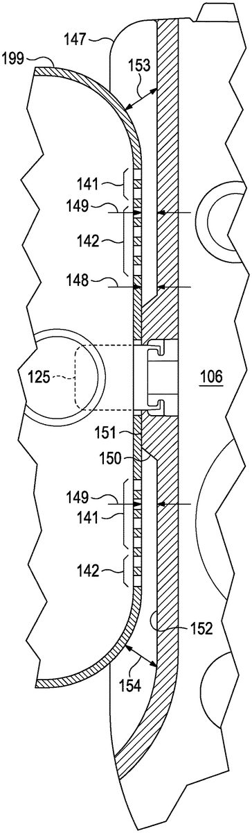
FIG.19is a detail view of the second handle102and mobile device199ofFIG.18.FIG.20is a partial, bottom-view cutaway of the second handle102and example mobile device199as defined inFIG.19.FIG.21is a partial, front-view cutaway of the second handle102and example mobile device199ofFIG.18. As illustrated inFIGS.19-21, configurations of the game controller100may include an acoustic waveguide145.
The acoustic waveguide145may be, as illustrated, at the juncture of the second handle102and the bridge119. The acoustic waveguide145is configured to redirect sound emitted from the mobile device199, such as through the speaker access holes141of the mobile device199, toward one or more of the front side of the game controller100, the top side of the game controller100, and the bottom side of the game controller100. Arrows146inFIGS.18and19illustrate the approximate directions in which the acoustic waveguide145is configured to redirect sound. As used in the context of redirecting sound, “in a direction toward the user” means toward one or more of the front side of the game controller100, the top side of the game controller100, and the bottom side of the game controller100.
In configurations, sound traveling toward the back side of the game controller100(meaning the side opposite to the front side of the game controller100), may be reflected by a backstop portion147of the acoustic waveguide145. Sound reflected by the backstop portion147of the acoustic waveguide145is redirected toward one or more of the front side of the game controller100, the top side of the game controller100, and the bottom side of the game controller100. In configurations, the backstop portion147of the acoustic waveguide145is integrated with the guide portion114of the second handle102.
Accordingly, sound emitted from the mobile device199is redirected toward the user (in typical use of the game controller100) by the acoustic waveguide145. In the reverse direction, sound coming from the user or near the user, such as the user's voice, is directed toward the microphone access holes142of the mobile device199by the acoustic waveguide145. Consequently, in configurations the game controller100does not have its own loudspeaker because the game controller100is configured to direct sound waves from the loudspeaker. In addition, in configurations the game controller100does not have its own microphone because the game controller100is configured to direct sound waves toward the microphone of the mobile device199. In configurations, the handle with the acoustic waveguide145(labeled as the second handle102in the illustrated configuration) does not have a loudspeaker, does not have a microphone, or does not have either.
Additionally, in configurations the game controller100does not have any holes or other internal passages whose purpose is to allow sound from the mobile device199to pass through the game controller100(or, specifically, the second handle102) to reach the user (or for sound from the user to reach the microphone access holes142of the mobile device199) because external surfaces of the game controller100(or, specifically, the second handle102) are configured to direct sound waves from the loudspeaker (and also toward the microphone of the mobile device199).
In configurations, the acoustic waveguide145includes an acoustic gap148between the second handle102and the mobile device199. The acoustic gap148is configured to provide a pathway to channel sound from the mobile device199toward at least one of the front side of the game controller, the top side of the game controller, and the bottom side of the game controller. In configurations, in the same way the acoustic gap148is configured to provide a pathway to channel sound toward the microphone access holes142of the mobile device199.
Preferably, the acoustic gap148has a gap width149between about 0.5 mm and about 4 mm. More preferably, the gap width149is between about 1.5 mm and about 3 mm. Even more preferably, the gap width149is between 1.75 mm and 2.25 mm. As illustrated inFIG.20, the gap width149is the distance between the mobile device199and the acoustic reflector152(described below) at the location of the speaker access holes141of the mobile device199. A gap width149outside of the preferred range may cause sound emitted by the speaker access holes141of the mobile device199to either be too attenuated (a smaller gap width149) or too diffuse (a wider gap width149). In each case, the sound may not be sufficiently directed toward the user.
In configurations, the second handle102includes a standoff protrusion150. The standoff protrusion150is configured to maintain the acoustic gap148between the second handle102and the mobile device199. The acoustic gap148, at its narrowest, is the distance between a distal end151of the standoff protrusion150and the acoustic reflector152(described below). The acoustic gap148, however, may widen toward a top portion153of the acoustic gap148or a bottom portion154of the acoustic gap148, an example of which is illustrated inFIG.21. In configurations, the connector125, as discussed above, extends from the standoff protrusion150.
In configurations, the acoustic waveguide145includes an acoustic reflector152. The acoustic reflector152is configured to direct sound from the mobile device toward at least one of the front side of the game controller, the top side of the game controller, and the bottom side of the game controller. As illustrated inFIGS.17-21, in configurations the acoustic reflector152defines one boundary of the acoustic gap148, and the acoustic reflector152is positioned across the acoustic gap148from the speaker access holes141of the mobile device. In configurations, the acoustic reflector152is molded into the main body portion106of the second handle102. In configurations, the acoustic reflector152may be or include an arcuate surface155whose center of curvature156is within the acoustic gap148or otherwise outside of the main body portion106of the second handle102.
EXAMPLES
Illustrative examples of the disclosed technologies are provided below. A particular configuration of the technologies may include one or more, and any combination of, the examples described below.
Example 1 includes a game controller for a mobile device, the game controller comprising: a first handle configured to contact and support a mobile device, the first handle comprising a user-accessible, first hardware interface on a main body portion of the first handle and configured to accept touch inputs; a bridge extending from the main body portion of the first handle; and an acoustic waveguide at a juncture of the first handle and the bridge, the acoustic waveguide configured to redirect sound emitted from the mobile device toward at least one of a front side of the game controller, a top side of the game controller, and a bottom side of the game controller.
Example 2 includes the game controller of Example 1, in which the acoustic waveguide is configured to redirect sound emitted from the mobile device toward the front side of the game controller and at least one of the top side of the game controller and the bottom side of the game controller.
Example 3 includes the game controller of any of Examples 1-2, in which the acoustic waveguide comprises an acoustic gap between the first handle and a mobile device supported by the first handle, the acoustic gap configured to channel sound from the mobile device toward at least one of the front side of the game controller, the top side of the game controller, and the bottom side of the game controller.
Example 4 includes the game controller of Example 3, in which the acoustic waveguide further comprises an acoustic reflector, the acoustic reflector defining one boundary of the acoustic gap, the acoustic reflector configured to direct sound from the mobile device toward at least one of the front side of the game controller, the top side of the game controller, and the bottom side of the game controller.
Example 5 includes the game controller of Example 4, in which the acoustic reflector is molded into the main body portion of the first handle.
Example 6 includes the game controller of any of Examples 1-5, in which the game controller includes no loudspeaker.
Example 7 includes the game controller of any of Examples 1-6, in which the game controller includes no microphone.
Example 8 includes the game controller of any of Examples 1-7, in which the first handle includes a standoff protrusion, the standoff protrusion configured to maintain an acoustic gap between the first handle and a mobile device to be supported by the first handle, the acoustic gap being a minimum distance between a distal end of the standoff protrusion and an acoustic reflector, the acoustic reflector configured to direct sound from the mobile device toward at least one of the front side of the game controller, the top side of the game controller, and the bottom side of the game controller.
Example 9 includes the game controller of Example 8, further comprising a connector extending from the standoff protrusion, the connector configured to provide physical and electrical connection to the mobile device.
Example 10 includes the game controller of any of Examples 8-9, in which the acoustic reflector comprises an arcuate surface having a center of curvature outside of the main body portion of the first handle.
Example 11 includes the game controller of any of Examples 1-10, further comprising a second handle configured to contact and support a mobile device, the second handle comprising a user-accessible, second hardware interface on a main body portion of the second handle and configured to accept touch inputs, the bridge extending from the main body portion of the second handle and coupling the second handle to the first handle.
Example 12 includes the game controller of Example 11, in which a guide portion of the first handle extends from the main body portion of the first handle and along the bridge, the guide portion of the first handle configured to align the bridge with the main body portion of the first handle, and in which a guide portion of the second handle extends from the main body portion of the second handle and along the bridge, the guide portion of the second handle configured to align the bridge with the main body portion of the second handle.
Example 13 includes the game controller of any of Examples 1-12, the acoustic waveguide comprising a backstop portion configured to redirect sound emitted from the mobile device away from a back side of the game controller and toward at least one of the front side of the game controller, the top side of the game controller, and the bottom side of the game controller.
Example 14 includes a game controller for a mobile device, the game controller comprising: a first handle configured to contact and support a mobile device, the first handle comprising a user-accessible, first hardware interface on a main body portion of the first handle and configured to accept touch inputs; a bridge extending from the main body portion of the first handle; and an acoustic waveguide at a juncture of the first handle and the bridge, the acoustic waveguide configured to redirect sound emitted from the mobile device in a direction toward a user of the game controller.
Example 15 includes the game controller of Example 14, in which the acoustic waveguide comprises an acoustic gap between the first handle and a mobile device supported by the first handle, the acoustic gap configured to channel sound from the mobile device in the direction toward the user of the game controller.
Example 16 includes the game controller of Example 15, in which the acoustic waveguide further comprises an acoustic reflector, the acoustic reflector defining one boundary of the acoustic gap, the acoustic reflector configured to direct sound from the mobile device in the direction toward the user of the game controller.
Example 17 includes the game controller of any of Examples 14-16, in which the game controller includes no loudspeaker and no microphone.
Example 18 includes the game controller of any of Examples 14-17, in which the first handle includes a standoff protrusion, the standoff protrusion configured to maintain an acoustic gap between the first handle and a mobile device to be supported by the first handle, the acoustic gap being a minimum distance between a distal end of the standoff protrusion and an acoustic reflector, the acoustic reflector configured to direct sound from the mobile device toward at least one of the front side of the game controller, the top side of the game controller, and the bottom side of the game controller.
Example 19 includes the game controller of any of Examples 14-18, further comprising a second handle configured to contact and support a mobile device, the second handle comprising a user-accessible, second hardware interface on a main body portion of the second handle and configured to accept touch inputs, the bridge extending from the main body portion of the second handle and coupling the second handle to the first handle.
Example 20 includes the game controller of any of Examples 14-19, the acoustic waveguide comprising a backstop portion configured to redirect sound emitted from the mobile device away from a back side of the game controller and in the direction toward the user of the game controller.
Aspects may operate on a particularly created hardware, on firmware, digital signal processors, or on a specially programmed general purpose computer including a processor operating according to programmed instructions. The terms “controller” or “processor” as used herein are intended to include microprocessors, microcomputers, ASICs, and dedicated hardware controllers. One or more aspects may be embodied in computer-usable data and computer-executable instructions, such as in one or more program modules, executed by one or more computers (including monitoring modules), or other devices. Generally, program modules include routines, programs, objects, components, data structures, etc. that perform particular tasks or implement particular abstract data types when executed by a processor in a computer or other device. The computer executable instructions may be stored on a non-transitory computer readable medium such as a hard disk, optical disk, removable storage media, solid state memory, RAM, etc. As will be appreciated by one of skill in the art, the functionality of the program modules may be combined or distributed as desired in various configurations. In addition, the functionality may be embodied in whole or in part in firmware or hardware equivalents such as integrated circuits, field programmable gate arrays (FPGA), and the like. Particular data structures may be used to more effectively implement one or more aspects of the disclosed systems and methods, and such data structures are contemplated within the scope of computer executable instructions and computer-usable data described herein.
The previously described versions of the disclosed subject matter have many advantages that were either described or would be apparent to a person of ordinary skill. Even so, all of these advantages or features are not required in all versions of the disclosed apparatus, systems, or methods.
Additionally, this written description makes reference to particular features. It is to be understood that the disclosure in this specification includes all possible combinations of those particular features. For example, where a particular feature is disclosed in the context of a particular example configuration, that feature can also be used, to the extent possible, in the context of other example configurations.
Also, when reference is made in this application to a method having two or more defined steps or operations, the defined steps or operations can be carried out in any order or simultaneously, unless the context excludes those possibilities.
Furthermore, the term “comprises” and its grammatical equivalents are used in this application to mean that other components, features, steps, processes, operations, etc. are optionally present. For example, an article “comprising” or “which comprises” components A, B, and C can contain only components A, B, and C, or it can contain components A, B, and C along with one or more other components.
Although specific example configurations have been described for purposes of illustration, it will be understood that various modifications may be made without departing from the spirit and scope of the disclosure.
Claims
- A game controller for a mobile device, the game controller comprising: a first handle configured to contact and support a mobile device, the first handle comprising a user-accessible, first hardware interface on a main body portion of the first handle, wherein the first hardware interface is configured to accept touch inputs;a bridge extending from the main body portion of the first handle;and an acoustic waveguide at a juncture of the first handle and the bridge, the acoustic waveguide configured to redirect sound emitted from the mobile device in a direction toward a user of the game controller;wherein the game controller lacks holes configured to allow sound from the mobile device to pass through the game controller.
- The game controller of claim 1, wherein the acoustic waveguide comprises an acoustic gap between the first handle and the mobile device, the acoustic gap configured to channel sound from the mobile device in the direction toward the user of the game controller.
- The game controller of claim 1, wherein the game controller includes no loudspeaker and no microphone.
- The game controller of claim 1, wherein the first handle includes a standoff protrusion, the standoff protrusion configured to maintain an acoustic gap between the first handle and the mobile device, the acoustic gap being a minimum distance between a distal end of the standoff protrusion and an acoustic reflector, the acoustic reflector configured to direct sound from the mobile device toward at least one of a front side of the game controller, a top side of the game controller, and a bottom side of the game controller.
- The game controller of claim 1, further comprising a second handle configured to contact and support the mobile device, the second handle comprising a user-accessible, second hardware interface on a main body portion of the second handle that is configured to accept touch inputs, the bridge extending from the main body portion of the second handle and coupling the second handle to the first handle.
- The game controller of claim 1, wherein the acoustic waveguide comprises a backstop portion configured to redirect sound emitted from the mobile device away from a back side of the game controller and in the direction toward the user of the game controller.
Disclaimer: Data collected from the USPTO and may be malformed, incomplete, and/or otherwise inaccurate.