U.S. Pat. No. 12,263,401
ERGONOMIC GAME CONTROLLER AND SYSTEM
AssigneeHIT BOX, L.L.C.
Issue DateDecember 18, 2023
Illustrative Figure
Abstract
A gaming controller includes a series of button assemblages corresponding to various game input functions. The assemblages are angled such that an operator's fingers are aligned with buttons resulting minimal tilting of the wrist. The gaming controller includes modifier buttons that change the strength of corresponding button input. A controller operating system includes a controller circuit with a processor configured to perform various functionalities. The operating system further includes a plurality of settings and sub-settings, at least some of which being related to user profiles, modifier button settings, and/or override systems. A method includes connecting the gaming controller to a video monitor and changing at least one setting associated with at least one of a user profile, a modifier button, and an override system that is saved on a local memory.
Description
DETAILED DESCRIPTION Example embodiments will now be described more fully with reference to the accompanying drawings. In general, the subject embodiments are directed to a gaming controller and operating system. However, the example embodiments are only provided so that this disclosure will be thorough, and will fully convey the scope to those who are skilled in the art. Numerous specific details are set forth such as examples of specific components, devices, and methods, to provide a thorough understanding of embodiments of the present disclosure. It will be apparent to those skilled in the art that specific details need not be employed, that example embodiments may be embodied in many different forms and that neither should be construed to limit the scope of the disclosure. In some example embodiments, well-known processes, well-known device structures, and well-known technologies are not described in detail. Referring to the Figures, wherein like numerals indicate corresponding parts throughout the views, the gaming controller and system of operation is intended for increasing improving ergonomics and functionality of arcade-style gaming controllers. As it will be appreciated with further reading, the improved ergonomics of the present invention reduces the muscle and tendon injuries associated with gaming. Moreover, the gaming controller and system of operation provides an improved functionality and compatibility with both technology and personal gaming preferences. A few example conventional game console controllers20,21are shown inFIGS.1A and1B. Although these controllers look different there are a number of similarities in there and most other conventional controllers. For example, each controller20,21includes a control pad22with four directional buttons corresponding to left, right, up, and down. Each controller20,21further includes at least two trigger buttons28(but typically four) and at least two action buttons30(but typically four). In addition, each controller20,21includes a joystick32. However, the controller20inFIG.1Aincludes two joysticks32, wherein to the controller21inFIG.1Bonly includes one joystick32. Instead ...
DETAILED DESCRIPTION
Example embodiments will now be described more fully with reference to the accompanying drawings. In general, the subject embodiments are directed to a gaming controller and operating system. However, the example embodiments are only provided so that this disclosure will be thorough, and will fully convey the scope to those who are skilled in the art. Numerous specific details are set forth such as examples of specific components, devices, and methods, to provide a thorough understanding of embodiments of the present disclosure. It will be apparent to those skilled in the art that specific details need not be employed, that example embodiments may be embodied in many different forms and that neither should be construed to limit the scope of the disclosure. In some example embodiments, well-known processes, well-known device structures, and well-known technologies are not described in detail.
Referring to the Figures, wherein like numerals indicate corresponding parts throughout the views, the gaming controller and system of operation is intended for increasing improving ergonomics and functionality of arcade-style gaming controllers. As it will be appreciated with further reading, the improved ergonomics of the present invention reduces the muscle and tendon injuries associated with gaming. Moreover, the gaming controller and system of operation provides an improved functionality and compatibility with both technology and personal gaming preferences.
A few example conventional game console controllers20,21are shown inFIGS.1A and1B. Although these controllers look different there are a number of similarities in there and most other conventional controllers. For example, each controller20,21includes a control pad22with four directional buttons corresponding to left, right, up, and down. Each controller20,21further includes at least two trigger buttons28(but typically four) and at least two action buttons30(but typically four). In addition, each controller20,21includes a joystick32. However, the controller20inFIG.1Aincludes two joysticks32, wherein to the controller21inFIG.1Bonly includes one joystick32. Instead of a second joystick, the controller21inFIG.1Bincludes a sensor34wherein movement of the sensor is registered as an input. While provided as examples, these game console controllers20,21, particularly the controller20, include similar button arrangements and functionality to most other conventional gaming controllers
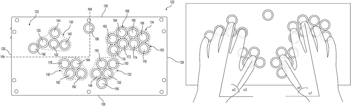
A plan view of the gaming controller120in accordance the present disclosure is shown inFIG.2. The gaming controller120defines a generally rectangular shape having a top surface122and bottom surface124(FIG.3) spaced apart by a pair of horizontal or longitudinal walls126and vertical or transverse walls128. The longitudinal walls126define a horizontal midpoint HM of the gaming controller120and the transverse walls128define a vertical midpoint VM of the gaming controller120. In accordance with one arrangement of the present disclosure, the gaming controller120includes a first assemblage of buttons130that generally corresponds to the first joystick of the prior art controllers20,21and a second assemblage of buttons132that generally corresponds to the second joystick (or sensor) of the prior art controllers20,21. The gaming controller120further includes a third assemblage of buttons134corresponding to a combination of triggers28and action buttons30of the prior art controllers20,21. One object of the present invention is to provide a large range of switchable settings to streamline personal playstyles and preferences. As such, there is a fourth assemblage of buttons136that modify aspects of the other buttons. In preferred embodiment and described in greater detail below, the fourth assemblage of buttons136preferably modifies the first assemblage of buttons130and/or the second assemblage of buttons132, which generally correspond to character/object movement that has historically been accomplished with a joystick or a D-pad. By-way of background, joysticks typically provide more inputs than simply digital readings on up, down, left, and right inputs, instead, they provide an analog system that includes a wide range of diagonal inputs and tilt inputs. The tilt input is a measure of strength input, the more the joystick tilts, greater the in-game response for certain video games. For example, a full tilt right may correspond with a character running right on screen, whereas a half tilt right may correspond with the character walking. More than just a half tilt and full tilt, intermediate levels of tilt can also provide unique in-game outcomes. The magnitude of tilt is derived from the predefined “center point” of the joystick, wherein the distance from the center point corresponds to a value of output. The value of output may be provided as a voltage value numeral from any number of large ranges, such as 0-225 wherein there are at least 225 potential values across the X-axis, the Y-axis, corresponding to even more values when diagonally held. As such, the modifier functions of the fourth assemblage of buttons136may provide one or more preselected “tilt” values in the buttons. In other words, the modifier provides the ability to assign each cardinal direction to a different specific analog point. For example, the cardinal left movement may be selected to be 75% tilt base, wherein becomes 45% tilt upon corresponding input of the modifier. Triggers likewise usually calibrate “0” as its constant center point that can be changed with a modifier if preselected in a player profile as will be described in greater detail below. Specific buttons of each assemblage will now be described in greater detail. It is preferable that all the buttons are arcade-style buttons, for example, Sanwa buttons.
Still referring the example layout presented inFIG.2, the first assemblage of buttons130includes four movement buttons (and/or analog directional buttons) including a left movement button138, a right movement button140, an up movement button142, and a down movement button144. Adjacent to the first assemblage of buttons130is an override modifier button146. The override modifier button146is set to correspond to either of the afore described “half tilt” and “full tilt” settings. When override modifier button146is set to a “half tilt” setting and held in combination any of the four movement buttons, the on screen object movement is slower than when the button is not held. Oppositely, when override modifier button146is set to a “full tilt” setting and held in combination any of the four movement buttons, the on screen object movement is faster than when the button is not held.
The second assemblage of buttons132preferably corresponds to the left joystick of the conventional controllers20,21. The second assemblage of buttons132includes four second movement buttons (and/or analog directional buttons) corresponding to a right joystick including a second left movement button148, a second right movement button150, a second up movement button152, and a second down movement button154. Adjacent to the first assemblage of buttons132is a second override modifier button156. The second override modifier button156functions similarly to the first override modifier button146and can be set to correspond to either of the afore described “half tilt” and “full tilt” settings that directly affect the strength of the second assemblage of buttons132.
The third assemblage of buttons134includes a first group of action buttons158and a second group of action buttons160. The first group of action buttons158preferably corresponds the trigger buttons of conventional controllers20. The first group of action buttons158comprises four trigger buttons including a first trigger button162, a second trigger button164, a third trigger button166, and a fourth trigger button168. The second group of action buttons160preferably corresponds to the action buttons of conventional controllers20. The second group of action buttons160comprises four action buttons including a first action button170, a second action button172, a third action button174, and a fourth action button176. However, these and other buttons may be remapped in other arrangements to be any combination of triggers, modifiers, action buttons, and movement buttons.
The fourth assemblage of buttons136preferably modifies the first assemblage of buttons130and/or the second assemblage of buttons132and includes four modifier buttons. The four modifier buttons includes a first modifier button178, a second modifier button180, a third modifier button182, and a fourth modifier button184. In one preferred arrangement, the first modifier button178changes the corresponding tilt of the left movement button138and/or second left movement button148. The second modifier button180changes the corresponding tilt of the right movement button140and/or the second right movement button150. The third modifier button182changes the corresponding tilt of the up movement button142and/or the second up movement button152. The fourth modifier button184changes the corresponding tilt of the down movement button144and/or and a second down movement button154. In an alternative setting or player profile, the first modifier button178, the second modifier button180, the third modifier button182, and the fourth modifier button184can correspond to X and Y axis modification. For example, the first modifier button178and the second modifier button180can correspond to modifying tilt strength in the X-axis and the third modifier button182and the fourth modifier button184can correspond to the Y-axis tilt strength. Likewise, one or more modifiers may affect X and Y tilt strength simultaneously. In addition, one or more modifiers may change the movement buttons between a base analog setting (no tilt to somewhere between 1-254 value) to digital (full tilt or no tilt).
In addition to the afore described buttons, a menu button186is also disposed on the top surface122of the gaming controller120. The menu button186functions similarly to start or menu buttons typically used in conventional controllers20,21and once selected can be operated via the same or other buttons.
It is one object of the invention that the gaming controller120include a layout that corresponds to a human hand. A human hand is shown inFIG.2Bto illustrate the ergonomics of the gaming controller120. When the average human hand is relaxed, it includes, as measured from the wrist, a pinky extending the shortest distance, an index finger extending the next shortest distance, a ring finger extending a longer distance than the index finger, and a middle finger extending the longest distance. Moreover, when relaxed, the joints between the distal, middle, and proximal phalanges are slightly bent. It should be appreciated that the buttons on the left side of the vertical midpoint are generally operated with a user's left hand while the buttons on the right side of the vertical midpoint are generally operated with a user's right hand. When the button assemblages on the left side are spaced closely to the buttons assemblages on the right side, the button assemblages are slightly angled at an angle α to correspond to a wrist to elbow angle to prevent a tilting of the wrist. In other words, the closer the left and right assemblages (and hands during use), the further a user's elbows need to be for the hands to be disposed over each assemblage. As such, the closer the left side buttons are to the right side buttons the greater the angle α of assemblages. Preferably, the right side angle α1is equal and opposite to the left side angle α2. It is also preferable that the relative angles α1, α2are angled towards the VM and are within 45° of each other, more preferably within 30° of each other, and more preferably yet within 25° of each other. It should also be appreciated that the first assemblage of buttons130and the third assemblage of buttons134are intended to be preferably operated with the left hand fingers and the right hand fingers, respectively. In addition, the second assemblage of buttons132and the fourth assemblage of buttons136are intended to be preferably operated with the right hand thumb and the left hand thumb, respectively. As such, vertically adjacent buttons in each assemblage correspond to the angle of the phalanges of the fingers and are preferably spaced such that an adjacently lower phalange sits on an adjacently lower button while inputting the adjacently higher buttons with distal phalanges. As illustrated, the average relaxed thumb extends at angles α3, α4from the extension of the wrist. During play, movement of the hand (particularly the right hand between action button sub-assemblages) will naturally be along the angles α.
Looking now toFIG.3, the gaming controller120is shown from side view. One of the vertical transverse walls128includes a series of ports187for electrically connecting the gaming controller120to several different devices, including but not limited to: a USB, a computer, gaming console, a joystick188such as a nunchuck inFIG.1B(or any other digital or analog joystick such as a Sanwa JLF Joystick), a wireless relay device, movement sensors, a mouse, other conventional gaming controllers, foot pedals, dance pads, and other inputs. In addition, the game controller120may also include internal wireless communication devices (seeFIG.4) such as Bluetooth, cellular, radio, and other forms of a wireless networking. A first setting switch190and a second setting switch192(shown as toggle switches) are also presented along the vertical transverse wall128. The first setting switch190and a second setting switch192will be described in greater detail below but ultimately allow for separate profiles and modifies for multiple players or specific preferences for individual games to be saved within the controller120. The setting switches190,192can change the keyboard configurations, the modification button settings (button correspondence and ranges), the tilt settings and ranges, and other settings. The switches can be used to select D-pad or modifier input, i.e., digital inputs bound to an analog bind. This is particularly useful for older games that only recognize digital inputs. While not limited thereto these switches can also change the function of 136 buttons (178,180,182,184) back and forth between D-pad22function and modifiers. Preferably one switch corresponds to switching between the digital “D-Pad” or analog “Tilt” mode and the other switch corresponds to button remapping, however, other preferences may be saved. In the present embodiment, each switch includes three settings (toggle left, toggle right, and non-toggle) that can be used in combination with settings of the other switch. It should be appreciated however, that there be more than two switches190,192. Likewise, it should also be appreciated that the switches could be replaced with dials having any number of settings, for example over three settings, over five settings, or over ten settings. Further, the game controller may include one or more sensors133, such as infrared, or other sensors such that movement of the gaming controller120corresponds to movement on screen.
FIG.4illustrates a controller circuit200in accordance with one embodiment of the invention. The various elements provided therein allow for a specific implementation. Thus, one of ordinary skill in the art of electronics and circuits may substitute various components to achieve a similar functionality. The circuit200includes a power circuit system202, a GCU system204, a communications module206, a server network208, a computing system210, and a button circuit system211.
The power system202includes a power supply circuit212and a battery circuit216that are both monitored via a power supervision circuit214. The battery circuit216includes a battery, which may be rechargeable, may be primarily charged via the power supply circuit212, which may include a wired or wireless connection to a source of power. For example, the power supply circuit212may include a wired connection to a wall outlet, a computer, or a console, or a wireless induction charging system. A power testing unit218tests for current from the power supply circuit202to monitor power is being transmitted to the GCU system204. For example, the power testing unit218can prevent dangerous surges of current and/or low levels of battery power from the battery circuit216. A power warning LED220can be connected to the power testing unit218, wherein the power testing unit218may be configured to flash the LED upon a low level of battery charge or provide a solid illumination if the power supply circuit212is connected to a charging source. Likewise, the LED may change in color or flashing upon the battery circuit216obtaining a complete charge.
Electricity from the power system202is transferred to the GCU system204, which includes a controller222and the communications module206. The controller222includes a processor224and a memory226having machine readable non-transitory storage. Programs and/or software228(such as arduino IDE) are saved on the memory226and so is input data230obtained via the many buttons in a button circuit system211and profile data232related to saved user preferences. An authenticate data233is also saved on memory226and will be described in greater detail below. The processor224translates and carries out instructions based on the software228, input data230, and profile data232and transmits the instructions to the computing system210via the communications module206. The computing system210may include any type of computer, console, or like devices. The computing system210typically also includes or is connected to an audio output234and a screen236. In use the computing system210, for example a console, relays instructions from the communications module206and outputs them as actions that are visible via screen236. These action can include in game actions, i.e., character or options selections associated with a video game and these actions may further include selecting various types of profile data232via a user interface238as will be discussed in greater detail below. The communications module206can include wireless (e.g., Bluetooth) and or a wired connection (PC Port USB shown inFIG.3). In addition, the communications module206may be directly connected to the power supply circuit212such that during a wired connection with the communications module206to the computing system210charges the controller circuit200via power supply circuit212.
The computing system210may further include an internet connection240, which may be wired or wireless. The internet connection240provides access to the server network208for transmitting data between the memory226and the server network208. The server network208may store various types of data. For example, profile data232, software updates242, authentication data244, and social network data246, and controller service data248. In operation, as the GCU system204connects to the server network208via the computing system210, allowing the transmission of data between memory226and server208. Respective authentication data233,244can be matched such that when a particular controller GCU system204is connected to the server network208, options are provided based on historical use of that individual controller. For example, while the memory226may only be able to store a limited amount of profile data232(key layout, tilt sensitivity, modifiers, SOCD), other profile data232can be saved in the network208and accessed upon connection to internet. Authentication data233,244can further be used to connect an individual controller to various social media platforms associated with the controller. For example, social media connectivity may allow sharing video game content like profile data, game screenshots, high scores, streaming videos, and recording videos. The transfer and changing of various data between the memory, server, etc., can be selected via numerous visual ques in the user interface238. Importantly, various profile data can also be changed and saved via the user interface238without connection to the internet via software or data saved locally in either the memory226or computing system210that is displayed on the user interface238.
The button circuit system211connects to the variously described buttons to the rest of the controller circuit200. For example, these various buttons may include an override button circuitry248, a first assemblage of buttons circuitry230, a menu button circuitry286, a second assemblage of buttons circuitry132, a third assemblage of buttons circuitry234, a fourth assemblage of buttons circuitry136, a second modifier button156circuitry, and a sensor circuitry233. Inputs of the various buttons can be translated by the GCU system204in accordance with data saved on the memory226, for example, key networking. The GCU system204may further include a conversion module235that converts the velocity/distance in which a various button is pressed to a range of corresponding voltages that are used to represent specific values of the afore described “tilt.” For example, the conversion module235may include a potentiometer electrically connected to each button such that the axial distance or speed of button travel correlates directly or inversely to the degree of associated “tilt.” Alternatively, profile data can be saved to change between buttons such that all or select buttons are translated as digital on/off inputs, i.e., no tilt or full tilt only. While not explicitly shown inFIG.4, joystick circuitry may also be included on the button circuit system211. Likewise, the button layouts presented inFIGS.11A through12Iand variations thereof may also be included in the button circuit system211.
As illustrated inFIG.5throughFIG.9, the user interface238includes a browser system300visualized on the screen236. With initial reference toFIG.5, the browser system includes a plurality of profile data setting pages306. The plurality of profile data setting pages306includes a series of sub-page tabs308corresponding profile settings including a first profile page310, a second profile page312, and a third profile page314. Each profile page can include value modifiers of various buttons, joysticks, and sensors, i.e., modifying the correlation between the distance of button travel, joystick tilt, sensor movement with the degree of tilt input. These modifier settings can be set at various values to set the tilt magnitude of the cardinal directions, the neutral center position, and analog magnitude of left and right triggers. These setting may also include options for changing the center of the joystick or comparative buttons, i.e., the position of the button (or range of positions) before in game actions are registered. A corresponding visual indicator311is further provided as a meta view of the individual button settings. For example, in the event that a left movement button and a right movement button are pressed simultaneously, the modifier values will determine corresponding in game actions. If the left movement button has a larger modifier than the right movement button, then the pressing of both buttons simultaneously, will result in a left input less that of the right modifier value. The concept extends to any combinations: up and down combinations, upper left corner (up and left movement) and down right corner (down and right movement) combinations, etc. The modifier values can also be switched from analog to digital inputs. Each profile310,312,314may also include an associated button layout. As described above, the various profiles can be changed on-the-go via the first setting switch190and a second setting switch192(FIG.3).
Referring now toFIG.6A, browser system300further includes a second setting316for profile data that provides override options in instances wherein buttons are pressed in simultaneous opposing cardinal directions (“SOCD”). These override options are presented for both X-axis and Y-axis conflicting button presses. Stated another way, in instances where the left movement button138and the right movement button140are being pressed simultaneously, both inputs are conventionally neutralized such that the character or object appearing on the screen does not move. While a joystick cannot be simultaneously tiled in the left and right direction, the override system resolves this impossibility for a button assemblage joystick equivalent. The second setting316includes a series of override options318, which determine the direction of the game input, such as character movement. The override options318includes an X-axis override option320, a Y-axis override option322, a setting switch override option324, and a joystick enablement option325. The X-axis and Y-axis override options320,322include several selections. For example, a neutral selection is included where simultaneous pressing of opposing movement buttons negate or cancel each other out. In addition, there are selections that relate to the time at which the buttons are pressed, for example the first button to be pressed overrides the second, or vise-versa, example overrides are shown inFIG.6B through6F.FIG.6Bincludes a “first input priority” section wherein the first button pressed will always override the second opposing button pressed.FIG.6Cincludes a “second input priority” wherein the second button pressed will always override the first opposing button pressed. Another selection is “absolute override” (example shown inFIG.6D) based on direction, for example, left always overrides right and up always overrides down. In yet another option, shown inFIG.6Eas “Left XOR Right on SOCD,” the left movement input is based on XOR wherein holding of the left input nullifies the right input and the right input is based on an SOCD protocol.FIG.6Fshows yet another example wherein a left movement input is overridden by a right movement input which nullifies the left movement input. The XOR settings inFIGS.6E and6Fare similar to the absolute override scheme, however, when the overridden button is no longer pressed, the oppositely pressed button does not move the in game object until the oppositely pressed button is released and then pressed again. As will be described in detail below, the SOCD scheme can further be applied to analog readings wherein opposing cardinal values are subtracted and movement is in the direction of the largest cardinal value less the opposing cardinal value via the following formula ((opposing voltage A+opposing voltage B)/2).
Referring now toFIG.7, browser system300further includes a third setting326that provides button mapping options. Each user-profile includes a button mapping option for individual mapping associated with different players and/or for different games. In addition, to button mapping it includes a Fractional Input Bind data, i.e., an input bind that requires multiple inputs to trigger. The Fractional Input Bind data can implement input bind via a specific configuration of wire connections between buttons, i.e., a meta reader unit that recognizes specific buttons being simultaneously pressed and translates output command from a distinct module to the processor. Alternatively, the Fractional Input Bind data can be translated by the processor via profile data that recognizes specific simultaneous button inputs and translates that to an in-game output. For example, A+B=A+B+C, where “Pushbutton A” and “Pushbutton B” together simultaneously trigger fractional input bind C. As such, when a user presses Attack (A) and Special (B) simultaneously, it yields the input of Attack, Special, and Jump (Y) without actually pressing the Y button. In another example, A+B=C, where “Pushbutton A” and “Pushbutton B” together simultaneously trigger fractional input bind C and nullify and/or repurpose their normal functions. In one implementation, Left+Right buttons=Neutral. The Fractional Input Bind algorithm can also bind modifiers, for example, X1 modifier+X2 modifier grants a third unique modifier X3 for a third degree of “tilt.” Similarly Y1 modifier+Y2 modifier=Y3 modifier.
These fractional input binding settings can further include Multi-Input Binds, Negative Input Binds, Cycle Input Bind Modifiers, Nullify features, Lockouts, combinations therefore and additional binding options. In the Multi-Input Binds, profile settings further include the ability to assign multiple functions to one button. For example, buttons input bind is set to output “A” and “B” by only pressing “Y” (D-pad left+D-pad right input can be achieved by pressing one button). In the Negative input bind, an input bind that triggers its function when an input is disengaged, i.e., the button is no longer being pressed. In the Cycle Input Bind Modifiers, an input bind is selected to change functions with each input and/or output (AKA, allowing an auto-combo via pressing the same button repeatedly). In the Nullify binding, a function that temporarily disables of one or more other functions, such as a “kill switch” that disables other buttons when pressed. In the Lockout binding, preceding inputs can trigger the nullification of one or more inputs following a specific state for a certain amount of time. For example, if the “A” button is pressed, it prevents the “B” button from functioning for one second. In another example the “A” button is pressed and the “B” inputs upon release of “B”). A pushbutton input may further have a multi-input bind function bound as: engage, output “A”; disengage, output “B.” The various examples set forth herein are exemplary in nature and can be implemented with any of the modifier, function, and movement bottoms. While certain features may be available in some game menus as software features, the subject disclosure provides the ability to map specific binds to inputs on a controller interface hardware side as a default or customizable user experience.
FIG.8illustrates a fourth setting328of the browser system300that provides a graphical representation of all or certain of the above referenced settings in one user profile including graphical representations of the various cardinal settings, input binds, etc.
FIG.9illustrates a fifth setting330of the browser system300that provides controller information and social media platforms associated with social network data246. As described above, using authentication data233,244once a controller is connected to the browser system300and network208, an individual controller may be connected from the browser system300of the user interface238to various social media platforms associated with that controller or owner of the controller. More than one controller may be associated with one player and/or social media platform wherein more than one authentication data233may be associated with a single user.
These values and settings presented inFIGS.5through9can be programmed in browser system300and saved in memory226or server208. Moreover, the features described inFIGS.5through8can be saved as profile data232that can be switched on-the-go with toggle switches190,192.
FIG.10provides a method400of setting up user profile data specific to a user. The method400begins by communicating402to a video display or computing system, providing404a user interface with a plurality of settings as described above and changing at least one of the settings. The method400continues with storing406updated settings in the game controller, processing408the updated input settings, and changing410user profiles with a switch physically located on the game controller.
FIG.11AthroughFIG.11Wprovide various additional configurations of the buttons in accordance with the subject disclosure. It should be appreciated that the example embodiments presented inFIG.11AthroughFIG.11W, are preferably drawn to scale, however, variations of the buttons, gaming controller walls, and joysticks in both size and relative placement can vary without departing from the scope of the application. Moreover, relative placement of buttons and joysticks that are claimed are not meant to be limited by configuration, scale, sizes and relative placements in the preferred illustrated arrangements unless otherwise indicated within the claim. In addition, for those arrangements that include a joystick, the joystick can be replaced by any number of movement and modifier buttons as previously described (such as those shown inFIG.12AthroughFIG.12I). Any one of the buttons presented inFIG.11AthroughFIG.11Wcan be associated with movement, action, trigger, menu, and modifier buttons as previously described unless otherwise claimed. Moreover certain arrangements inFIG.11AthroughFIG.11Winclude similar button and joystick layout but include the first and second setting switches190,192in other locations i.e., an opposite vertical transverse wall128, one or both of the longitudinal walls126, and/or the top surface122. In addition, any one of the layouts may include a dial in place of or in addition to any of the buttons. The dial changes the modifier button or range of potentiometer values and/or the directional button cardinal values during gameplay by controlling the voltage input associated with button pressing. The variations presented inFIG.12AthroughFIG.12Ican be interchanged in the numerous controller layouts. The layout presented inFIG.11Ais similar in size and scale the layout inFIGS.2A and2B.
The layouts presented inFIG.12AthroughFIG.12Ican be mapped to perform any function, have any value, override, bindings, etc., as described above. However, in one arrangement they have a similar layout to that presented inFIG.2A. For example, each assemblage of buttons in the upper-right hand corner having a similar arcuate shape to assemblage134, may include the same functionality, i.e., trigger and action functions. The assemblage of buttons below arcuate-shaped assemblage may include functions similar to the second assemblage132presented inFIG.2A, with four buttons similar to a D-pad. These D-pad buttons are shown as circular, rectangular, square, or diamond shapes. The single button below the assemblage with D-pad functionality may be a modifier similar to the second override button156inFIG.2A. To the left of the horizontal midline HM and above the vertical midline VM is generally either an assemblage of four circular buttons or a joystick, which function similar to the first assemblage of buttons130inFIG.2A. A fifth button located to the left of the four circular buttons described in the previous sentence may be present and function similar to the first override modifier146presented inFIG.2A. To the left of the horizontal midline HM and below the vertical midline VM is another assemblage of typically four closely located buttons that function similarly to the assemblage136presented inFIG.2A. The circular buttons with a smaller radius presented inFIGS.11R and11Umay have similar functionality to the D-pad. InFIGS.11M and11N, the upper three buttons on the upper right side and the lowest button may have D-pad functionality, wherein the joystick is on the left. InFIGS.11R and11Tthe lowest circular button having the smallest radius is optionally present. InFIG.11Vthe diagonal buttons (diagonal button assemblages) on both the left and right lower sides may provide various functionality, for example the left diagonal button assemblage may provide a D-pad functionality and the right diagonal button assemblage may provide a right analog stick functionality wherein the small radius circular buttons near each diagonal button assemblage is a modifier for the adjacent assemblage.FIG.11Wprovides example functionality symbols of the buttons, wherein the larger arrows are similar to a joystick, i.e., can be combined or pressed in such a way for analog readings wherein the smaller arrows may provide D-pad functionality and the arcuate shape is similar in shape and functionality to the third assemblage presented inFIG.2A. Each D-pad functionality may be designed to be digital (full tilt or no tilt) and each other movement assemblage/joystick may be analog (full tilt, partial tilt, no tilt). Each circular button may be an arcade style circular button, however, the buttons could take other shapes in different embodiments.
Referring back toFIG.6A, in addition to the afore described SOCD profile settings, the following additional setting options are provided and related to selectable profile data232: A neutral SOCD is provided that nullifies inputs, for example, D-Pad ‘Left’ and D-Pad ‘Right’ simultaneously results in both inputs being nullified; An absolute override SOCD is provided wherein one button always take priority over another, for example, D-Pad ‘Down’ and D-Pad ‘Up’ simultaneously results in ‘Up’ input and nullifies ‘Down’ input regardless of which input was pressed first; A first input override is provided wherein the first button pressed takes priority, for example, D-Pad ‘Left’ and D-Pad ‘Right’ simultaneously results in the second input pressed being nullified; A second input override is provided wherein the second button pressed takes priority, for example, D-Pad ‘Left’ and D-Pad ‘Right’ simultaneously results in the first input pressed being nullified. Additional setting options related to selectable profile data232include: an exclusively only the first direction (XOR) setting, wherein the first direction is applied regardless of any opposing directional inputs until all directional inputs are released, for example, D-Pad ‘Left’ held first and D-Pad ‘Right’ held second will result in the D-Pad ‘Right’ being nullified until the user is holding neither D-Pad ‘Left’ nor D-Pad ‘Right;’ an exclusively only the second direction (Alternate XOR) setting, wherein the second direction is applied regardless of any opposing directional inputs until all directional inputs are released, for example, D-Pad ‘Left’ held first and D-Pad ‘Right’ held second will result in the D-Pad ‘Left’ being nullified until the user is holding neither D-Pad ‘Left’ or D-Pad ‘Right’ a second cardinal override once setting, wherein, the second direction overrides the first direction and whereafter the second direction becomes the new first direction when the first direction is released, for example, D-Pad ‘Left’ is held first and D-Pad ‘Right’ is held second, D-Pad ‘Right’ is the second direction and thus the preferred override resulting in the D-Pad ‘Left’ being nullified and D-Pad ‘Right’ being sent to the game console and once D-Pad ‘Left’ is released afterwards while D-Pad ‘Right’ is still being held down, then D-Pad ‘Right’ is now designated as the new first direction. Obviously, many of the afore described settings may be selected at once in the same profile.
Still referring back toFIG.6A, in addition to the afore described SOCD profile settings, the following additional settings related to SOCD resolution with one or more analog inputs are provided and related to selectable profile data232: a natural analog axis SOCD resolution wherein the resulting movement is the sum of the opposing analog directions (tilt), for example, Voltage A+Voltage B/2 when a potentiometer is used; a neutral analog SOCD, wherein, opposing tilts are nullified regardless of tilt/voltage; and absolute analog override, wherein, one direction always takes priority regardless of which direction is input first; a first analog input setting, wherein, the first direction input takes priority; a second analog input setting, wherein, the second direction input takes priority; a chosen analog input setting, wherein the user will specify which direction will override the other regardless of the input method or input order; an exclusively only the first analog direction, wherein, the first direction is applied regardless of any opposing directional inputs until all directional inputs are released; an exclusively only in the second analog direction, wherein, second direction is applied regardless of any opposing directional inputs until all directional inputs are released; an analog second cardinal overrides once, wherein, second direction overrides the first direction, whereafter, the second direction becomes the new first direction when the first direction is released. The afore described setting can be applied to any types of opposing analog inputs on an axis. Similar settings can include opposing inputs of analog triggers, levers, sensors, mouse, touchpad, actuators, gyroscopic, sensor fusion, and other means. Obviously, many of the afore described settings may be selected at once in the same profile.
In accordance with another aspect of the settings presented inFIG.6A, non-homogenous priority SOCD profile settings are provided, the following additional setting options are provided and related to selectable profile data232: A natural non-homogenous setting, wherein, all outputs from D-Pad, Left Analog Stick, and Right Analog Stick are input with no restrictions or priority; A hard override priority non-homogenous setting, wherein, one or more non-homogenous directional inputs are nullified, for example, D-Pad disables Left Analog Stick entirely when actuated or Left Analog Stick disables D-Pad entirely when actuated or D-Pad disables Right Analog Stick entirely when actuated or Right Analog Stick disables D-Pad entirely when actuated or Left Analog Stick disables Right Analog Stick entirely when actuated or Right Analog Stick disables Left Analog Stick entirely when actuated or Left Analog Stick hard overrides Right Analog Stick and D-Pad or Right Analog Stick hard overrides Left Analog Stick and D-Pad or D-Pad hard overrides Left Analog Stick and Right Analog Stick or Left Analog Stick or D-Pad hard overrides Right Analog Stick or Right Analog Stick or D-Pad hard overrides Left Analog Stick or Left Analog Stick or Right Analog Stick hard overrides D-Pad. Obviously, many of the afore described settings may be selected at once in the same profile.
When two button orientational direction inputs are redundant, one button (cardinal) may nullify the other. For example, if a user inputs ‘Left’ on D-Pad and ‘Left’ on Left Analog Stick simultaneously, then a SRCD priority of D-Pad would output only the ‘Left’ on D-Pad and nullify the ‘Left’ on Left Analog Stick. Redundant inputs may also result from non-homogenous input sources. In accordance with yet another aspect of the settings presented inFIG.6A, non-homogenous cross Simultaneous Redundant Cardinal Directions (SRCD) profile settings are provided, the following additional setting options are provided and related to selectable profile data232: SRCDs prioritize Left Stick and input nullifies D-Pad or SRCDs prioritize Left Stick nullifies Right Stick or SRCDs prioritize D-Pad—Right Stick or SRCDs prioritize D-Pad—Left Stick or SRCDs prioritize Right Stick—Left Stick or SRCDs prioritize Right Stick—D-Pad or SRCDs prioritize Left Stick or D-Pad disables Right Stick or SRCDs prioritize Left Stick or Right Stick disables D-Pad or SRCDs prioritize D-Pad or Right Stick disables Left Stick. Obviously, many of the afore described settings may be selected at once in the same profile.
Because of the afore described input mapping redundancies, SOCD conflicts can arise from combining input sources (D-Pad ‘Left’ and Left Analog Stick ‘Right’ simultaneously). In-game resolutions for these conflicts may be selected as additional profile data232: a hybrid setting wherein, certain directional button inputs may be conditionally nullified to resolve SOCD conflicts; A neutral selection setting, wherein, opposite inputs result in nullification of both; an absolute override system, wherein, one direction takes priority regardless of input (analog or digital); A first input override setting, wherein, the first input nullifies a conflicting directional input; A second input override setting, wherein, the second input nullifies a conflicting directional input; An exclusively only the first direction (XOR), wherein, the first direction is applied regardless of any opposing directional inputs until all directional inputs are released; An exclusively only the second direction (XOR) setting, wherein, the second direction is applied regardless of any opposing directional inputs until all directional inputs are released; A second cardinal overrides once setting, wherein, the second direction overrides the first direction, whereafter, the second direction becomes the new first direction when the first direction is released.
In accordance with another aspect of the settings presented inFIG.6A, D-Pad and right analog stick priority SOCD profile settings are provided, the following additional setting options are provided and related to selectable profile data232: A neutral setting wherein simultaneous pressing of opposing directions in the D-Pad and right analog nullify both inputs; An absolute override wherein one directional input take priority regardless of if the input is from the D-Pad and left analog; a first input override setting as previously described; A second input override setting as previously described; a chosen direction (absolute) setting as previously described; An exclusively only the first direction (XOR) setting as previously described; An exclusively only the second direction (XOR) setting as previously described; A second cardinal overrides once setting as previously described.
In accordance with another aspect of the settings presented inFIG.6A, D-Pad and left analog stick priority SOCD profile settings are provided, the following additional setting options are provided and related to selectable profile data232: A neutral setting wherein simultaneous pressing of opposing directions in the D-Pad and left analog nullify both inputs; An absolute override wherein one directional input take priority regardless of if the input is from the D-Pad and left analog; a first input override setting as previously described; A second input override setting as previously described; a chosen direction (absolute) setting as previously described; An exclusively only the first direction (XOR) setting as previously described; An exclusively only the second direction (XOR) setting as previously described; A second cardinal overrides once setting as previously described.
It should be appreciated that the foregoing description of the embodiments has been provided for purposes of illustration. In other words, the subject disclosure it is not intended to be exhaustive or to limit the disclosure. Individual elements or features of a particular embodiment are generally not limited to that particular embodiment, but, where applicable, are interchangeable and can be used in a selected embodiment, even if not specifically shown or described. Various features that are, for brevity, described in the context of a single embodiment, may also be provided separately or in any sub combination. Further, reference to values stated in ranges includes each and every value within that range. Such variations are not to be regarded as a departure from the disclosure, and all such modifications are intended to be included within the scope of disclosure.
Claims
- A gaming controller system comprising: a gaming controller having a surface including a plurality of buttons corresponding to in-game inputs, the surface extending horizontally from a first sidewall to a second sidewall and having a midpoint halfway between the first sidewall and the second sidewall, wherein the plurality of buttons comprises a first assemblage of buttons and a first modifier button, wherein the first modifier button is separate from the first assemblage of buttons, wherein the first assemblage of buttons and the second assemblage of buttons are located on different sides of the horizontal midpoint of the surface of the gaming controller;a local memory located within the gaming controller and having machine readable non-transitory storage including a profile data that modifies the in-game input;and a processor located within the gaming controller and configured to read the non-transitory storage in view of the profile data to modify the in-game inputs.
- The gaming controller system according to claim 1, wherein the profile data includes a plurality of gaming profiles preselected by a user and wherein the processor is further configured to select one of the plurality of gaming profiles.
- The gaming controller system according to claim 2, wherein each gaming profile includes distinct in-game inputs associated with the plurality of buttons.
- The gaming controller system according to claim 3, wherein the processor is further configured to select one of the plurality of gaming profiles in game without having to access a menu screen.
- The gaming controller system according to claim 3, wherein at least two gaming profiles include different preselected simultaneous opposing cardinal direction override protocols.
- The gaming controller system according to claim 5, wherein at least one of the simultaneous opposing cardinal direction override protocol includes an absolute override setting wherein one in-game input always overrides another opposing in-game input.
- The gaming controller system according to claim 5, wherein the gaming controller includes at least one joystick and at least one of the simultaneous opposing cardinal direction override protocols includes overriding one of opposing non-joystick inputs and joystick inputs in favor of the other opposing non-joystick inputs and joystick inputs.
- The gaming controller system according to claim 5, wherein at least one of the simultaneous opposing cardinal direction override protocol includes prioritized in-game input based upon which button is pressed first.
- The gaming controller system according to claim 2, further including a remote network including additional gaming profiles and the processor is further configured to move the additional gaming profiles to the memory.
- The gaming controller system according to claim 9, wherein the memory further includes authentication data and the software includes corresponding authentication data that is matched before providing access to the additional gaming profiles in the network.
- The gaming controller system according to claim 1, wherein the gaming surface does not include a joystick.
- The gaming controller system according to claim 2, wherein the processor is configured to switch between at least two of the gaming profiles with a toggle located on the controller.
- The gaming controller system according to claim 1, wherein the plurality of buttons includes a second assemblage of buttons and a second modifier button located adjacent to the second assemblage of buttons, and wherein the processor is configured to translate the holding of the second modifier button during pressing any of the buttons in the second assemblage of buttons as having a stronger in-game input than if the second modifier button is not held.
- The gaming controller system according to claim 13, wherein each button in the plurality of buttons located on the surface of the gaming controller is a circular arcade style button.
- A gaming controller system comprising: a gaming controller having a surface including a plurality of buttons corresponding to in-game inputs, the surface extending horizontally from a first sidewall to a second sidewall and having a horizontal midpoint halfway between the first sidewall and the second sidewall;the plurality of buttons including a first assemblage of buttons and a first modifier button located adjacent to, and separate from, the first assemblage of buttons, wherein the first assemblage of buttons includes a left button, an up button, a right button and a down button;and the plurality of buttons further including a second assemblage of buttons and a second modifier button located adjacent to, and separate from, the second assemblage of buttons, wherein the first assemblage of buttons and the second assemblage of buttons are located on different sides of the horizontal midpoint of the surface of the gaming controller.
- A gaming controller system comprising: a gaming controller having a surface having a first assemblage of buttons, a second assemblage of buttons, a third assemblage of buttons, and a fourth assemblage of buttons, wherein each assemblage of buttons corresponds to in-game inputs;a local memory located within the gaming controller and having machine readable non-transitory storage including a profile data that modifies the in-game input;a processor located within the gaming controller and configured to read the non-transitory storage in view of the profile data to modify the in-game inputs;and wherein the profile data further includes settings for the plurality of buttons corresponding to analog tilt percentage.
- The gaming controller system of claim 16, wherein the plurality of buttons includes at least one modifier button with a modifying the settings to the plurality of buttons corresponding to analog tilt percentage by pressing the at least one modifier button.
- The gaming controller system of claim 16, wherein the profile data includes a plurality of gaming profiles preselected by a user and wherein the processor is further configured to select one of the plurality of gaming profiles.
- The gaming controller system of claim 18, wherein the plurality of buttons includes a toggle button for switching between the plurality of gaming profiles.
Disclaimer: Data collected from the USPTO and may be malformed, incomplete, and/or otherwise inaccurate.