U.S. Pat. No. 12,263,400
Open and Close Features for Game Controller Bridge
AssigneeBackbone Labs, Inc.
Issue DateJanuary 5, 2024
Illustrative Figure
Abstract
A handheld gaming device in which configurations allow for default-open, force-close systems and separate the user's insertion of the mobile device and closure of the handles around the mobile device.
Description
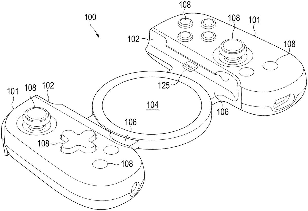
DETAILED DESCRIPTION As described herein, aspects are directed to apparatus and methods for securing and releasing a mobile device to and from a gaming device that interfaces with the mobile device. Configurations of the disclosed technology improve the user experience of inserting and removing a mobile device from the gaming device and reduces the risk of damage to both the mobile device and the gaming device. Aspects are now described in more detail. FIG.1depicts a gaming device for interfacing with a mobile device, in a closed position before the mobile device is inserted. For purposes of the disclosure, “mobile device” refers to a portable, handheld computing device, such as a smartphone, tablet, or other comparable mobile device. As illustrated inFIG.1, a gaming device100includes handles101, which may have compliant inner linings102, in configurations, to assist in securing the mobile device200in place for gameplay. Even so, not all configurations include compliant inner linings102. In configurations, the device100may also include a platform104structured to receive the mobile device200. The platform104is mounted to a bridge106, which connects the handles101and may be extended and retracted for inserting, securing, and removing the mobile device200. In configurations, the gaming device100may include a connector125structured to physically and electronically interface with the mobile device200. In other configurations, the interface is wireless. Each handle101in the illustrated configuration includes user-accessible, hardware interfaces108, such as one or more of a button, an analog stick, a touchscreen, a touchpad, a knob, a slider, a switch, a wheel, a dial, a directional pad, or another such feature configured to accept touch inputs from a user's finger or a stylus. FIG.2depicts the gaming device in an open position, where the handles101have been moved far enough apart (as indicated by the arrows inFIG.2) so that a mobile device200may be inserted to interface with the gaming device100. As ...
DETAILED DESCRIPTION
As described herein, aspects are directed to apparatus and methods for securing and releasing a mobile device to and from a gaming device that interfaces with the mobile device. Configurations of the disclosed technology improve the user experience of inserting and removing a mobile device from the gaming device and reduces the risk of damage to both the mobile device and the gaming device. Aspects are now described in more detail.
FIG.1depicts a gaming device for interfacing with a mobile device, in a closed position before the mobile device is inserted. For purposes of the disclosure, “mobile device” refers to a portable, handheld computing device, such as a smartphone, tablet, or other comparable mobile device. As illustrated inFIG.1, a gaming device100includes handles101, which may have compliant inner linings102, in configurations, to assist in securing the mobile device200in place for gameplay. Even so, not all configurations include compliant inner linings102. In configurations, the device100may also include a platform104structured to receive the mobile device200. The platform104is mounted to a bridge106, which connects the handles101and may be extended and retracted for inserting, securing, and removing the mobile device200. In configurations, the gaming device100may include a connector125structured to physically and electronically interface with the mobile device200. In other configurations, the interface is wireless. Each handle101in the illustrated configuration includes user-accessible, hardware interfaces108, such as one or more of a button, an analog stick, a touchscreen, a touchpad, a knob, a slider, a switch, a wheel, a dial, a directional pad, or another such feature configured to accept touch inputs from a user's finger or a stylus.
FIG.2depicts the gaming device in an open position, where the handles101have been moved far enough apart (as indicated by the arrows inFIG.2) so that a mobile device200may be inserted to interface with the gaming device100. As described in greater detail below, the gaming device100may open to this position via one of several mechanisms. Once the gaming device100has reached its open position, a user may begin inserting a mobile device200by engaging the mobile device200with the platform104. In configurations, the platform104may be magnetic to attract the mobile device200to the platform104. Accordingly, the platform104may provide an initial level of stability for the mobile device200on the bridge106before the handles101are closed.
FIG.3depicts the gaming device100and mobile device200in a position for gameplay, where the mobile device200is secured and connected to the gaming device100. As depicted, the handles101are brought laterally inward (as indicated by the arrows inFIG.3) once the mobile device200has been received by the platform104. In some configurations, when the handles101reach the edges of the mobile device200, compliant linings102may cushion and grip the edges of the mobile device200, providing stability and protection in the device's secured gameplay position. When gameplay is concluded, the mobile device200may be released and removed from the gaming device100, and the gaming device100may return to a closed state, such as depicted inFIG.1.
The configurations illustrated inFIGS.4-20are generally like the configuration illustrated inFIGS.1-3except as noted below.
FIGS.4-6illustrate the details of a mechanism for setting a gaming device400in its open position, according to a first example configuration. In this example configuration, one or more springs401located within the bridge106is in a compressed state when the device is in its closed position, such as inFIG.4. The user may initiate a release of the springs401via mechanical, electrical, magnetic, or other suitable trigger means402. For example, the user may press a button on the device that is mechanically structured to release the springs401from their compressed state within the bridge106or to otherwise unlock the bridge106, allowing the bridge106to extend from the closed position. The release of the springs401or unlocking of the bridge106could also be accomplished by an electrically operated release or a magnetically operated release. When the springs401are released, the springs401extend and cause the bridge106to extend (as indicated by the arrows inFIG.5). In this example configuration, the extension of the springs401does not move the platform104; rather, the platform104maintains a position substantially in the center of the handles101to assist in receiving the mobile device200. Once the mobile device200has been inserted, the handles101may be moved laterally inward (as indicated by the arrows inFIG.6), such as via a rack mechanism in an example configuration. In this example configuration, the handles101move inward at set indices until reaching the edges of the mobile device200. Once the handles101reach the edges of the mobile device, the handles101may move inward one final index, compressing the compliant linings102to secure the mobile device200. In configurations, the compliant linings102are structured to be thicker in width than the distance of a single index in the rack mechanism. As such, the compliant linings102may cushion the edges of the mobile device200while ensuring that the mobile device200is snugly secured between the handles101, accounting for discrepancies between the mobile device's dimensions and the widths of the rack indices. Even so, not all versions include the compliant linings102.
In alternative configurations, instead of or in addition to the springs401, the gaming device400may utilize compressed air or hydraulics to extend the bridge106from the closed position to the open position.
FIGS.7-9illustrate the details of another mechanism for setting a gaming device700in its open position, according to a second example configuration. In such configurations, portions of the bridge106, such as surfaces702and704, slide against each other during movement of the bridge106between the extended position to the retracted position. The friction of the sliding of the surfaces702and704resists lateral movement of the handles either inward or outward. Accordingly, the handles101may be pulled away from each other (as shown by the arrows inFIG.8) or pushed toward each other (as shown by the arrows inFIG.9) in response to a force, but the handles101remain stationary when no force is applied. As described, movement of the handles101to extend or retract the bridge106does not move the platform104.
In configurations, the sliding mechanism may include friction surfaces, a rack mechanism, or other suitable methods of resisting and forcing lateral movement.FIG.29shows an example of a configuration having controllable friction surfaces. As illustrated inFIG.29, the gaming device may include one or more sections where a springy material, such as a foam spring, biases a controllable friction material toward the bridge106or between sections of the bridge106. For example, as illustrated inFIGS.7-9, the bridge106may slide within one or both of the handle guide portions (identified as “tunnel” inFIG.29) during movement of the bridge106between the extended position and the retracted position. In such configurations, the controllable friction material may be located between the bridge106and one or both of the handle guide portions. The handle guide portion extends from the main body portion of the handle. As illustrated inFIG.29, in configurations there is more than one section of controllable friction material. The controllable friction material may be, as examples, silicone, styrene-butadiene rubber (SBR), polytetrafluoroethylene (PTFE), acetal, or synthetic resinous plastic material, such as the plastic material provided under the DELRIN® brand owned by Dupont Polymers, Inc.
FIG.30shows an example of a rack mechanism to resist movement of the bridge106between the extended position and the retracted position (including vice versa). As illustrated inFIG.30, the bridge106may include a rack that engages a spring-mounted tooth. Hence when the bridge106is either extended or retracted, the spring-mounted tooth provides resistance to movement of the bridge106by engaging the rack.
Configurations of the sliding mechanism may also include a damper to smooth the lateral movement and improve the user experience.FIG.31shows an example of a game controller having a rotary damper. As illustrated inFIG.31, a gear may engage with a rack coupled to the bridge106, causing the gear to rotate as the bridge106extends and retracts. The gear, in turn, may be coupled to a rotary damper to resist rotation of the gear. The rotary damper may include, for example, a viscous fluid or friction material to oppose rotation of the gear.
FIGS.10-12illustrate the details of another mechanism for setting a gaming device1000in its open position, according to a third example configuration. In this configuration, a spring mechanism1002within the bridge106includes two states. In the spring mechanism's first state, one or more springs within the bridge106tend to force the bridge106into a closed position when no outside force is acting on the gaming device1000; hence the gaming device1000remains in a closed position. A user may then pull the handles101laterally away from each other to a set distance, extending the springs and triggering the spring mechanism1002to enter its second state. In the second state, rather than biasing the bridge106in the closed position, the spring mechanism1002biases the bridge106in the open position to allow for reception of the mobile device200. The set distance noted is less than the distance between the handles101that would be required to insert the mobile device200between the handles101. That insertion distance is approximately what is shown inFIG.11, where the mobile device200would just fit into the gaming device1000. Preferably, the set distance is less than half of the insertion distance. More preferably, the set distance is less than one-quarter of the insertion distance. Accordingly, the user only has to separate the handles106a small amount, less than the full open distance, at which point the spring mechanism1002changes from the first state to the second state, rapidly pushing apart the handles106without user interaction. Once in the open state, the handles106stay biased apart. The spring mechanism1002may include one or more bi-stable springs.
Upon reception of the mobile device200, the user may pull the handles101laterally away from each other once again, and the spring mechanism1002will exit its second stable state and revert to the first state, creating an inward force and securing the compliant linings102around the edges of the mobile device200.
The same mechanism can be used in the reverse direction to make the gaming device1000more compact. In particular, the mobile device200can be removed from the gaming device1000, and the user can begin to push the handles toward each other. At a particular distance between the handles, the spring mechanism1002changes from the second state to the first state, rapidly pushing the handles106together without user interaction.
FIGS.13-16detail a fourth configuration for a gaming device1300, in which the platform104includes a magnet1302. In this configuration, a user may bring their mobile device200near the platform104, causing the platform104to move away from the remainder of the gaming device1300due to attraction of the magnet1302to the mobile device200, such as to a magnetic plate beneath the rear face of the mobile device200. The platform104may be secured to the gaming device1300via a spring1304, in configurations.
Once the platform104attaches to the rear face of the user's mobile device200, the user may extend the handles101(see the arrows inFIG.15), allowing the spring1304or other suitable means to pull the mobile device200toward the bridge106. Once the mobile device200makes contact with the bridge106or the platform104is otherwise reseated on the bridge106(such as shown inFIG.15), the user may retract the handles101(see the arrows inFIG.16) to secure the mobile device200to the gaming device1300. Accordingly, in such configurations, the magnetic force between the platform104and the mobile device200is greater than the retractive force of the spring1304. Once the platform104is magnetically connected to the mobile device200, the user may let go of the mobile device200to have both of the user's hands available to extend the handles101, thus facilitating attachment of the mobile device200to the gaming device1300. The configuration ofFIGS.13-16may also include the features discussed above forFIGS.4-12.
FIGS.17-20illustrate another mechanism for opening and closing a gaming device1700, according to a fifth example configuration. Similar to the previous configuration, the platform104in this configuration includes a magnet structured to attract a mobile device, such as through a magnetic plate beneath the rear face of the mobile device. The platform104is pivotably connected to the bridge106. In the illustrated configuration, the bridge106comprises arms1702and arms1704that are rotatably connected at joints1706. In configurations, arms1704are slidably connected to the platform104. In the device's closed position, arms1702and arms1704may create an angle, and the platform104may sit above the plane of the handles101, such as shown inFIG.17. A user may bring their mobile device200near the platform104, causing the magnet to attract the mobile device200and hold it in place on the platform104. With the mobile device200in place on the platform104, the user may then pull the handles101laterally away from each other (in the direction shown by the arrows inFIG.18), causing the arms1702and arms1704to pivot and lower into a substantially horizontal position. Lowering the arms1702and the arms1704to substantially horizontal accordingly lowers the platform104into the same plane as the handles, such as shown inFIG.19. When the platform104has been lowered, the handles101may then be retracted a small amount to secure the mobile device200in place for gameplay.
As described for various configurations above, the platform104may include a magnet structured to attract a rear surface of a user's mobile device. In configurations, the attraction utilizes internal magnetic technology within the mobile device, such as Apple MagSafe technology as applied to iPhones.
FIGS.21-28illustrate another mechanism, according to a sixth example configuration. As illustrated inFIGS.21-28, the platform104may be secured to the gaming device2100via a pivot2101, and two examples are shown.
FIGS.21-24illustrate the platform104being directly coupled to one of the handles101through a pivot2101. In that regard,FIG.21is a bottom view of a handheld gaming device2100having a platform104that is pivotally connected to a handle101of the gaming device2100.FIG.22is a bottom view of the handheld gaming device2100, illustrating an example mobile device200being positioned for attachment to the platform104, while the bridge106of the handheld gaming device2100is in a closed position.FIG.23is a bottom view of the handheld gaming device2100, illustrating the example mobile device200coupled to the platform104, while the bridge106of the handheld gaming device2100is in the closed position.FIG.24is a bottom view of the handheld gaming device2100, illustrating the example mobile device200coupled to the platform104, while the bridge106of the handheld gaming device2100is in an open position. The connection of the platform104to the handle101may be biased by a spring mechanism2102to a retracted configuration, such as shown inFIG.24, where the platform104is substantially parallel to the bridge106. As used in this context, “substantially parallel” means largely or essentially equidistant at all points, without requiring perfect parallelism. In other configurations, the connection to the handle101may be biased by a spring mechanism2102to an extended configuration, such as shown inFIG.22, where the platform104is angled away from the bridge106. The mobile device200may be coupled to the platform104through, for example, one or more magnets2103.
FIGS.25-28illustrate the platform104being coupled to one of the handles101through a pivot2502, with an additional link2501coupling the platform104to the pivot2502. In that regard,FIG.25is a bottom view of a handheld gaming device2500having a platform104pivotally connected to a handle101of the gaming device2500through an additional link2501.FIG.26is a bottom view of the handheld gaming device2500, illustrating an example mobile device200being positioned for attachment to the platform104, while the bridge106of the handheld gaming device2500is in a closed position.FIG.27is a bottom view of the handheld gaming device2500, illustrating the example mobile device200coupled to the platform104, while the bridge106of the handheld gaming device2500is in the closed position.FIG.28is a bottom view of the handheld gaming device2500, illustrating the example mobile device200coupled to the platform104, while the bridge106of the handheld gaming device2500is in an open position. The connection to the handle101may be biased by a spring mechanism2503to a retracted configuration, such as shown inFIG.28, where the platform104and the additional link2501are each substantially parallel to the bridge106. In other configurations, the connection to the handle101may be biased by a spring mechanism2503to an extended configuration, such as shown inFIG.26, where the additional link2501is angled away from the bridge106. In configurations, there may be spring mechanism at the pivot joint2504between the platform104and the additional link2501. In configurations, there may be more than one additional link2501between the platform104and the pivot2502. The mobile device200may be coupled to the platform104through, for example, one or more magnets2505.
Configurations of the described invention improve the user experience for handheld gaming devices interfacing with mobile devices. Existing handheld gaming devices require forcing the device open before inserting the mobile device, which can pose difficulties for users performing both motions at once. Configurations described in this disclosure allow for default-open, force-close systems and separate the user's insertion of the mobile device and closure of the handles around the mobile device. Separating these motions not only makes use of the device easier, but it also prevents the potential for dropping and/or damaging either the mobile device or the device due to the described difficulties.
The previously described versions of the disclosed subject matter have many advantages that were either described or would be apparent to a person of ordinary skill. Even so, all of these advantages or features are not required in all versions of the disclosed apparatus, systems, or methods.
Additionally, this written description makes reference to particular features. It is to be understood that the disclosure in this specification includes all possible combinations of those particular features. For example, where a particular feature is disclosed in the context of a particular example configuration, that feature can also be used, to the extent possible, in the context of other example configurations.
Furthermore, the term “comprises” and its grammatical equivalents are used in this application to mean that other components, features, steps, processes, operations, etc. are optionally present. For example, an article “comprising” or “which comprises” components A, B, and C can contain only components A, B, and C, or it can contain components A, B, and C along with one or more other components.
Also, directions such as “vertical,” “horizontal,” “right,” and “left” are used for convenience and in reference to the views provided in figures. But the gaming device may have a number of orientations in actual use. Thus, a feature that is vertical, horizontal, to the right, or to the left in the figures may not have that same orientation or direction in actual use.
Although specific example configurations have been described for purposes of illustration, it will be understood that various modifications may be made without departing from the spirit and scope of the disclosure.
The applicant intends to encompass within the language any structure presently existing or developed in the future that performs the same function.
Claims
- A handheld gaming device comprising: a first handle comprising a first user-accessible hardware interface;a second handle comprising a second user-accessible hardware interface;a platform;a first arm associated with the first handle and rotatably connected with the platform at a first pivot point;a second arm associated with the second handle and rotatably connected with the platform at a second pivot point;and a connector on one of the first and second handles, the connector configured to electronically connect to an input port of a mobile device;wherein: when the first and second arms are rotated to a first position, the first and second handles are slidably movable between a first extended position and a second extended position;in the first extended position, a length between the first and second handles is longer than a length of the mobile device;and in the second extended position, the length between the first and second handles is about the length of the mobile device.
- The handheld gaming device of claim 1, wherein the first and second arms are rotatably connected at a bottom of the platform.
- The handheld gaming device of claim 1, wherein the first arm is rotatably connected at an edge of the platform.
- The handheld gaming device of claim 1, wherein the first arm is coupled with the first handle via a first additional arm that is fixed to the first handle, and wherein the first additional arm is rotatably connected with the first arm.
- The handheld gaming device of claim 4, wherein the second arm is coupled with the second handle via a second additional arm that is fixed to the second handle, and wherein the second additional arm is rotatably connected with the second arm.
- The handheld gaming device of claim 1, wherein the platform comprises a magnet.
- The handheld gaming device of claim 1, wherein the first and second handles comprise respective compliant linings configured to cushion and grip edges of the mobile device.
- The handheld gaming device of claim 1, wherein the first and second handles comprise respective overhangs.
- The handheld gaming device of claim 1, wherein the first and second user-accessible hardware interfaces each comprise one or more of a button, an analog stick, a touchscreen, a touch pad, a knob, a slider, a switch, a wheel, a dial, a directional pad, a finger touch input, or a stylus touch input.
- The handheld gaming device of claim 1, wherein: the first user-accessible hardware interface comprises a first joystick, a directional pad positioned below the first joystick, and a first set of diagonally-arranged buttons positioned below the directional pad;and the second user-accessible hardware interface comprises four buttons arranged in a diamond pattern, a second joystick positioned below the four buttons, and a second set of diagonally-arranged buttons positioned below the second joystick.
- The handheld gaming device of claim 1, wherein a length of the platform is less than a length of the mobile device.
- The handheld gaming device of claim 1, wherein the platform is positioned between inside edges of the first and second handles when the first and second arms are rotated to the first position.
- The handheld gaming device of claim 1, wherein an overall length of the handheld gaming device is reduced when the first and second arms are rotated to a second position as compared to when the first and second arms are rotated to the first position.
- A handheld gaming device comprising: a first handle comprising a first user-accessible hardware interface;a second handle comprising a second user-accessible hardware interface;and a plurality of pivotable arms coupling the first and second handles, wherein the plurality of pivotable arms are movable between an angled position and a substantially-horizontal position;wherein the mobile device is receivable between the first and second handles when the plurality of pivotable arms are in the substantially-horizontal position.
- The handheld gaming device of claim 14, wherein an overall length of the handheld gaming device is reduced when the plurality of pivotable arms are in the angled position as compared to when the plurality of pivotable arms are in the substantially-horizontal position.
- The handheld gaming device of claim 14, wherein the first and second handles are slidably movable between a first extended position and a second extended position.
- The handheld gaming device of claim 14, further comprising a platform, wherein ends of two of the plurality of pivotable arms are rotatably connected with the platform.
- The handheld gaming device of claim 17, wherein ends of two of the plurality of pivotable arms are rotatably connected at a bottom of the platform.
- The handheld gaming device of claim 14, further comprising a connector on one of the first and second handles, wherein the connector is configured to electronically connect to an input port of the mobile device.
- The handheld gaming device of claim 14, wherein the first and second handles comprise respective compliant linings configured to cushion and grip edges of the mobile device.
- The handheld gaming device of claim 14, wherein the first and second handles comprise respective overhangs.
- A handheld gaming device comprising: a first handle comprising a first user-accessible hardware interface;a second handle comprising a second user-accessible hardware interface, wherein the first and second handles are slidably movable between a first position and a second position;a first arm coupled with the first handle and rotatably connected with the platform at a first pivot point;a second arm coupled with the second handle and rotatably connected with the platform at a second pivot point;a mobile device support surface, wherein the mobile device support surface is positioned between inside edges of the first and second handles when the first and second arms are rotated to a first position;and an electrical connector on one of the first and second handles, wherein the electrical connector is configured to mate with a mobile device port.
- The handheld gaming device of claim 22, wherein the first and second arms are rotatably connected at a bottom of the mobile device support surface.
- The handheld gaming device of claim 22, wherein the first arm is rotatably connected at an edge of the mobile device support surface.
- The handheld gaming device of claim 22, wherein the first arm is coupled with the first handle via a first additional arm that is coupled with the first handle, wherein the first additional arm is rotatably connected with the first arm.
- The handheld gaming device of claim 22, wherein the second arm is coupled with the second handle via a second additional arm that is coupled with the second handle, wherein the second additional arm is rotatably connected with the second arm.
- The handheld gaming device of claim 22, wherein the mobile device support surface comprises a magnet.
- The handheld gaming device of claim 22, wherein the first and second handles comprise respective compliant linings.
- The handheld gaming device of claim 22, wherein the first and second handles comprise respective overhangs.
Disclaimer: Data collected from the USPTO and may be malformed, incomplete, and/or otherwise inaccurate.