Illustrative Figure
Abstract
An example game controller includes a housing main body formed by connecting a housing member on a front surface side and a housing member on a back surface side. On the left and right of the housing main body, holding portions are provided. To the left and right holding portions, a pair of grip portions covering the entirety of the holding portions are connected. A boundary portion between two housing members is covered with a grip portion. Thus, when a user grips the grip portion, the grip portion is likely to fit the hand well. Thus, it is possible to improve the operability.
Description
DETAILED DESCRIPTION OF NON-LIMITING EXAMPLE EMBODIMENTS With reference to the drawings, a game controller1according to an exemplary embodiment is described below.FIG.1is a diagram showing an example of a game system including the game controller1according to the exemplary embodiment. As shown inFIG.1, the game system includes the game controller1, a game apparatus100, and a display apparatus200. The game apparatus100includes a CPU, a RAM, and a storage device (a non-volatile memory, an optical disc, a magnetic disk, or the like) (not shown). The CPU of the game apparatus100can execute game processing based on a predetermined game program, and outputs the result of the game processing to the display apparatus200. As the display apparatus200, for example, a liquid crystal display apparatus or an organic EL display apparatus may be used. It should be noted that the game apparatus100may be a stationary game apparatus, or may be a mobile game apparatus integrated with the display apparatus200. Further, the game apparatus100is not limited to an apparatus designed for games, and may be an information processing apparatus capable of executing any program for a personal computer, a smartphone, or the like other than a game program. The game apparatus100and the game controller1are connected together in a wired or wireless manner, and operation data corresponding to an operation performed on the game controller1is output to the game apparatus100. For example, the game controller1and the game apparatus100may be connected together using Bluetooth (registered trademark). The details of the game controller1are described below.FIG.2is an external view of the game controller1. (a) ofFIG.2is a front view of the game controller1. (b) ofFIG.2is a left side view of the game controller1. (c) ofFIG.2is a right side view of the game controller1. (d) ofFIG.2is a top view of the game controller1. (e) ofFIG.2is a bottom view of the game controller1. (f) ofFIG.2is ...
DETAILED DESCRIPTION OF NON-LIMITING EXAMPLE EMBODIMENTS
With reference to the drawings, a game controller1according to an exemplary embodiment is described below.FIG.1is a diagram showing an example of a game system including the game controller1according to the exemplary embodiment.
As shown inFIG.1, the game system includes the game controller1, a game apparatus100, and a display apparatus200. The game apparatus100includes a CPU, a RAM, and a storage device (a non-volatile memory, an optical disc, a magnetic disk, or the like) (not shown). The CPU of the game apparatus100can execute game processing based on a predetermined game program, and outputs the result of the game processing to the display apparatus200. As the display apparatus200, for example, a liquid crystal display apparatus or an organic EL display apparatus may be used. It should be noted that the game apparatus100may be a stationary game apparatus, or may be a mobile game apparatus integrated with the display apparatus200. Further, the game apparatus100is not limited to an apparatus designed for games, and may be an information processing apparatus capable of executing any program for a personal computer, a smartphone, or the like other than a game program.
The game apparatus100and the game controller1are connected together in a wired or wireless manner, and operation data corresponding to an operation performed on the game controller1is output to the game apparatus100. For example, the game controller1and the game apparatus100may be connected together using Bluetooth (registered trademark).
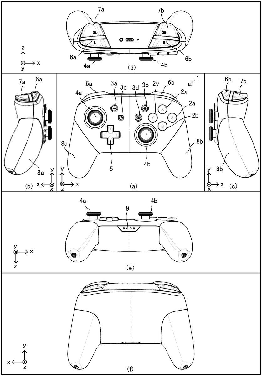
The details of the game controller1are described below.FIG.2is an external view of the game controller1. (a) ofFIG.2is a front view of the game controller1. (b) ofFIG.2is a left side view of the game controller1. (c) ofFIG.2is a right side view of the game controller1. (d) ofFIG.2is a top view of the game controller1. (e) ofFIG.2is a bottom view of the game controller1. (f) ofFIG.2is a rear view of the game controller1. An xyz coordinate system inFIG.2is a coordinate system with respect to the game controller1and is defined such that a direction perpendicular to a front surface of the game controller1(e.g., a direction of pressing an A-button2a) is a z-axis direction, a left-right direction of the game controller1(e.g., a direction connecting the A-button2aand a Y-button2y) is an x-axis direction, and an up-down direction of the game controller1(e.g., a direction connecting a B-button2band an X-button2x) is a y-axis direction.
As shown in (a) ofFIG.2, in a right region of the front surface of the game controller1, an A-button2a, a B-button2b, an X-button2x, and a Y-button2yare placed. Further, on the right side in a center region of the front surface of the game controller1, a plus button3band a home button3dare placed. Further, below the Y-button2yand the home button3d, a right analog stick4bis placed.
Further, on the left side in the center region of the front surface of the game controller1, a minus button3aand a capture button3care placed. Further, in a left region of the front surface of the game controller1, a left analog stick4ais placed. Further, below the minus button3aand the capture button3c, a directional pad5is placed.
The A-button2a, the B-button2b, the X-button2x, and the Y-button2yare buttons capable of being pressed in a depth direction (a positive z-axis direction) in (a) ofFIG.2and are buttons used for a game operation. Further, the minus button3a, the plus button3b, the capture button3c, and the home button3dare buttons capable of being pressed in the positive z-axis direction. The home button3dmay be used for, for example, an operation different from a game operation. If the home button3dis pressed, a menu screen or a setting screen of the game apparatus100may be displayed. For example, a user can press the home button3dat any timing while the game apparatus100is executing a game program. If the home button3dis pressed while a game program is being executed, the game program that is being executed is interrupted, and a predetermined menu screen is displayed. Further, by the pressing of the home button3d, an on state and an off state of a power supply of the game apparatus100or an on state and an off state of the sleep of the game apparatus100may be controlled. The capture button3cis a button used to capture, for example, an image displayed on the display apparatus200. The capture button3cand the home button3dare buttons that are not used for a normal game operation and therefore are used less frequently than other buttons for a game operation (the A-button2a, the B-button2b, the X-button2x, the Y-button2y, an L-button6a, an R-button6b, a ZL-button7a, a ZR-button7b, and the like) during a game. It should be noted that the details of the structure of the home button3dwill be described later.
Further, the left analog stick4aand the right analog stick4bare devices for indicating a direction and are each configured such that a stick portion operated by the finger of the user can be tilted in any directions (at any angles in up, down, left, right, and oblique directions). It should be noted that the left analog stick4aand the right analog stick4bmay be able to be pressed in the positive z-axis direction. The directional pad5is a device for indicating the up, down, left, and right directions.
It should be noted that the positions of the left analog stick4a, the directional pad5, the right analog stick4b, the A-button2a, the B-button2b, the X-button2x, and the Y-button2yare not limited to those shown inFIG.2. For example, the left analog stick4amay be provided at the position of the directional pad5shown inFIG.2, and the directional pad5may be provided at the position of the left analog stick4ashown inFIG.2. Further, the right analog stick4bmay be provided at the positions of the A, B, X, and Y-buttons shown inFIG.2, and the A, B, X, and Y-buttons may be provided at the position of the right analog stick4bshown inFIG.2.
Further, the directional pad5may not be configured as an integrated key top, and may be configured as independent four buttons. That is, a button corresponding to the up direction of the directional pad5, a button corresponding to the right direction of the directional pad5, a button corresponding to the down direction of the directional pad5, and a button corresponding to the left direction of the directional pad5may be provided as independent buttons.
The key tops of the left analog stick4aand the right analog stick4bare the same in shape, size, and material. The left analog stick4aand the right analog stick4b, however, are different in the weight of tilting the analog stick (the magnitude of the force required to tilt the analog stick at the same angle). Specifically, within each of the left analog stick4aand the right analog stick4b, an elastic member (a spring) is provided, and the key top is configured such that when the key top is tilted, the key top returns to the previous position by the restoring force of the elastic member. The characteristics (the spring constants) of these elastic members provided within the analog sticks are different, whereby the left analog stick4aand the right analog stick4bare different in weight.
Specifically, the left analog stick4ais lighter than the right analog stick4b. Although depending on the game program executed by the game apparatus100, for example, the left analog stick4ais used for the operation of moving a game character. On the other hand, the right analog stick4bis used to move a virtual camera or move a target for the user to take aim. In a case where an object is moved using an analog stick, and if the analog stick is too light, the analog stick is greatly tilted by a small force. Thus, the user cannot move the object as intended. Thus, the right analog stick4bis heavier than the left analog stick4a, whereby, for example, in a case where the virtual camera is moved using the right analog stick4b, it is possible to move the virtual camera more finely and improve the operability.
It should be noted that the left analog stick4aand the right analog stick4bmay be the same in weight. Alternatively, the right analog stick4bmay be lighter than the left analog stick4a. Yet alternatively, the left analog stick4aand the right analog stick4bmay be different in shape, size, and material.
It should be noted that to vary the operational feelings of the left analog stick4aand the right analog stick4b, other than the weights of the left analog stick4aand the right analog stick4b, the left analog stick4aand the right analog stick4bmay be configured as follows. For example, the left analog stick4aand the right analog stick4bmay be different in the tilting range (the movable range) of the key top. Alternatively, the left analog stick4aand the right analog stick4bmay be different in sensitivity (resolution). For example, the tilting range of the right analog stick4bis greater than that of the left analog stick4a, whereby it is possible to perform a more precise operation when moving the virtual camera or the target. Further, the sensitivity of the right analog stick4bis lower than the left analog stick4a, whereby it is possible to perform a precise operation. Thus, it is possible to prevent an unintended input. Conversely to the above, the tilting range of the left analog stick4amay be greater than that of the right analog stick4b. Alternatively, the sensitivity of the left analog stick4amay be lower than that of the right analog stick4b. Further, the left analog stick4aand the right analog stick4bmay be different in any one, or two or more, of “weight”, “tilting range”, and “sensitivity”.
FIG.3is a diagram showing an example of a top surface portion of each of the left analog stick4aand the right analog stick4b.FIG.3is a side view of the top surface portion (a portion to be touched by the user) of the analog stick4aor4b. As shown inFIG.3, a top surface of each of the left analog stick4aand the right analog stick4bhas a recessed portion in its center. The recessed portion is circular when the analog stick is viewed from above. The recessed portion is so shaped as to slightly swell upward. The height of the highest portion of the recessed portion is approximately the same as the height of the highest portion of an outer periphery of the recessed portion. Further, on a side surface of the top surface portion of each of the left analog stick4aand the right analog stick4b, a plurality of ribs (recesses and protrusions) that go around the top surface are formed in a concentric circle. This makes the finger of the user likely to be caught on the side surface of the top surface portion of the analog stick. That is, when the analog stick is tilted in any direction, the finger of the user is less likely to slide. This improves the operability. Further, in a center portion of the top surface of the analog stick, a rib is not provided, thereby improving the feel when the finger of the user operates the analog stick.
Further, as shown in (e) ofFIG.2, four LEDs9are provided on a lower surface of the game controller1. If a plurality of game controllers1are connected to the game apparatus100, the LEDs9emit light so that each game controller1can be identified by the user. For example, if four game controllers1are connected to the game apparatus100, then in a first game controller1, only the first one from the left among the four LEDs9emits light. In a second game controller1, only the second one from the left among the four LEDs9emits light. In a third game controller1, only the third one from the left among the four LEDs9emits light. In a fourth game controller1, only the fourth one from the left among the four LEDs9emits light. It should be noted that each of a plurality of game controllers may be distinguished by the number of beams of light emitted by the four LEDs9.
As shown inFIG.2, to the left and right of the center of the game controller1, grip portions8aand8b, which protrude downward (in a negative y-axis direction), are provided, respectively. The grip portion8ais held by the left hand of the user. The grip portion8bis held by the right hand of the user. As shown in (b) and (c) ofFIG.2, the grip portions8aand8bare formed so as to be curved in the direction of a back surface of the game controller1(the positive z-axis direction).
Further, as shown in (d) ofFIG.2, on an upper surface of the game controller1, an L-button6a, a ZL-button7a, an R-button6b, and a ZR-button7bare provided. Specifically, the L-button6ais provided in a left end portion on the upper surface of the game controller1. The ZL-button7ais provided to the side of the L-button6acloser to the back surface of the game controller1(further in the positive z-axis direction). Further, the R-button6bis provided in a right end portion on the upper surface of the game controller1. The ZR-button7bis provided to the side of the R-button6bcloser to the back surface of the game controller1(further in the positive z-axis direction).
The L-button6a, the R-button6b, the ZL-button7a, and the ZR-button7bare buttons used for a game operation. The ZL-button7aand the ZR-button7bmay be trigger buttons.
Further, each of the buttons (A, B, X, Y, L, R, ZL, and ZR-buttons) in the exemplary embodiment is a button capable of outputting a signal (an ON/OFF signal) indicating whether or not the button is pressed. Alternatively, in another exemplary embodiment, each of the ZL-button7aand the ZR-button7bmay be a button capable of outputting an analog value corresponding to the amount of pressing of the button. For example, if the user pushes down the ZL-button7aor the ZR-button7bto a first position, an analog value corresponding to the first position may be output. If the user pushes down the button to a second position below the first position, an analog value corresponding to the second position may be output.
FIG.4is a diagram showing the state where the user holds the game controller1with both hands. As shown inFIG.4, if the user holds the grip portion8awith their left hand and holds the grip portion8bwith their right hand, the user can operate the left analog stick4aand the directional pad5with the thumb of the left hand. Further, the user can operate the minus button3aand the capture button3cwith the thumb of the left hand. Further, the user can operate the L-button6aand the ZL-button7awith the index finger (or the middle finger) of the left hand. Further, the user can operate the A-button2a, the B-button2b, the X-button2x, the Y-button2y, the right analog stick4b, the plus button3b, and the home button3dwith the thumb of the right hand. Further, the user can operate the R-button6band the ZR-button7bwith the index finger (or the middle finger) of the right hand. It should be noted thatFIG.4shows the typical manner of holding the game controller1. Depending on the user, the game controller1may be held in a different manner of holding the game controller1.
Details of L/R Button and ZL/ZR Button
Next, a description is given of the details of the L-button6a, the ZL-button7a, the R-button6b, and the ZR-button7b, which are provided on the upper surface of the game controller1.
FIG.5is an exploded perspective view of the game controller1. As shown inFIG.5, a housing10of the game controller1is formed by connecting a first housing10aon the front surface side of the game controller1and a second housing10bon the back surface side of the game controller1. Within the housing10, a button frame30is accommodated. Further, within the housing10, a first substrate20and a second substrate40are accommodated.
FIG.6is an external view of the button frame30. (a) ofFIG.6is a front view of the button frame30(a diagram showing the button frame30as viewed from the front of the game controller1). (b) ofFIG.6is a left side view of the button frame30. (c) ofFIG.6is a right side view of the button frame30. (d) ofFIG.6is a top view of the button frame30. (e) ofFIG.6is a bottom view of the button frame30. It should be noted that an x-axis, a y-axis, and a z-axis inFIG.6correspond to the x-axis, the y-axis, and the z-axis, respectively, inFIG.2.
FIG.7is an external view of the key top of the ZR-button7b. (a) ofFIG.7is a front view of the key top of the ZR-button7b(a diagram showing the key top of the ZR-button7bas viewed from the front of the game controller1). (b) ofFIG.7is a right side view of the key top of the ZR-button7b. (c) ofFIG.7is a top view of the key top of the ZR-button7b. (d) ofFIG.7is a rear view of the key top of the ZR-button7b. (e) ofFIG.7is a bottom view of the key top of the ZR-button7b. (f) ofFIG.7is a perspective view of the key top of the ZR-button7b. It should be noted that an x-axis, a y-axis, and a z-axis inFIG.7correspond to the x-axis, the y-axis, and the z-axis, respectively, inFIG.2.
It should be noted that the ZL-button7aand the ZR-button7bare symmetrical, and the ZL-button7aand the ZR-button7bhave the same shape. Further, the L-button6aand the R-button6bare symmetrical, and the L-button6aand the R-button6bhave the same shape. Hereinafter, although only either one of the ZL-button7aand the ZR-button7bwill be described, the same applies to the other button. Further, although only either one of the L-button6aand the R-button6bwill be described, the same applies to the other button. Further, hereinafter, the L-button6aand the R-button6bwill occasionally be collectively referred to as an “L/R button6”, and the ZL-button7aand the ZR-button7bwill occasionally be collectively referred to as a “ZL/ZR button7”.
As shown inFIG.6, the L-button6a, the R-button6b, the ZL-button7a, and the ZR-button7bare formed integrally with a frame portion33, which is accommodated within the housing10. Further, as will be described later, a button detection section for each button is also formed integrally. If the button frame30is accommodated in the housing10, the L-button6a, the R-button6b, the ZL-button7a, and the ZR-button7bare exposed through an upper surface of the housing10.
Description of L/R Button
As shown in (d) ofFIG.6, the R-button6bis so shaped as to be horizontally long (is so shaped as to be long in the x-axis direction). That is, the R-button6bis formed such that the length of the R-button6bin the direction of the side surface of the game controller1is longer than the length of the R-button6bin the direction of the back surface of the game controller1. Further, the further in the direction of the side surface (the further in a positive x-axis direction) from the center of the game controller1, the smaller the width of the R-button6b.
Further, as shown in (a) ofFIG.6, the further in the direction of the side surface from the center in the left-right direction of the game controller1, the further downward the R-button6bslopes overall.
Specifically, as shown in (a) ofFIG.6, in an end portion of the R-button6bon the center side in the left-right direction of the game controller1(further in a negative x-axis direction), a sloping portion61b, which slopes downward, is provided.FIG.8Ais a partially enlarged view of the R-button6bas viewed from its front.FIG.8Bis a partially enlarged view of the R-button6bas viewed from its upper surface.FIG.8Cis a partially enlarged view of the R-button6bas viewed from its right side surface.
More specifically, as shown inFIGS.8A and8B, the sloping portion61in the end portion of the R-button6bon the center side of the game controller1slopes in two steps. A portion of the R-button6bclose to the end portion on the center side of the game controller1has a greater sloping angle. That is, the sloping portion61bof the R-button6bincludes a portion on the side surface side and a portion on the center side. With respect to the horizontal direction (the x-axis direction in the xyz coordinate system), the sloping angle of the portion on the center side is greater than the sloping angle of the portion on the side surface side.
Further, as shown in (a) ofFIG.6, in an end portion of the R-button6bon the side surface side in the left-right direction of the game controller1(further in the positive x-axis direction), a sloping portion62b, which slopes downward, is provided.
Specifically, as shown inFIGS.8A and8B, the end portion of the R-button6bon the side surface side of the game controller1slopes in two steps. A portion of the R-button6bclose to the end portion on the side surface side of the game controller1has a greater sloping angle. That is, the sloping portion62bof the R-button6bincludes a portion on the side surface side and a portion on the center side. With respect to the horizontal direction (the x-axis direction in the xyz coordinate system), the sloping angle of the portion on the side surface side is greater than the sloping angle of the portion on the center side.
Further, as shown in (c) ofFIG.6, in an end portion of the R-button6bon the front surface side of the game controller1(further in a negative z-axis direction), a sloping portion63b, which slopes downward, is provided.
Specifically, as shown inFIG.8C, the sloping portion63bin the end portion of the R-button6bon the front surface side of the game controller1slopes in two steps. A portion of the R-button6bclose to the end portion on the front surface side of the game controller1has a greater sloping angle. That is, the sloping portion63bof the R-button6bincludes a portion on the front surface side and a portion on the back surface side. With respect to the horizontal direction (the z-axis direction in the xyz coordinate system), the sloping angle of the portion on the front surface side is greater than the sloping angle of the portion on the back surface side.
As described above, the sloping portion61bis provided in the R-button6bon the center side of the game controller1, whereby it is easy for even a person having a long finger to operate the R-button6b. That is, if the finger of the user is long, and when the user operates the R-button6b, the tip of the finger reaches the end portion of the R-button6bon the center side of the game controller1. The sloping portion61b, however, is provided in the end portion on the center side, whereby the sloping portion61bfits the finger, and it is easy for the user to operate the R-button6b.
Further, the sloping portion62bis provided in the end portion of the R-button6bon the side surface side of the game controller1, whereby it is easy for both a person having a long finger and a person having a short finger to operate the R-button6b. That is, a user having a short finger can operate the R-button6bby placing the tip of the finger on the end portion of the R-button6bon the side surface side of the game controller1. On the other hand, when a user having a long finger operates the R-button6b, the extremity of the index finger hits the end portion of the R-button6bon the center side, and a portion near the base or the second joint of the finger hits the end portion of the R-button6bon the side surface side. The sloping portion62bis provided in the end portion on the side surface side, whereby, when the end portion of the R-button6bon the center side is pressed by the extremity of the index finger, it is possible to make small a force (a force by reaction) applied to the portion near the base or the second joint of the finger, and make it easy for the user to press the R-button6b.
Further, the sloping portion63bis provided in the end portion of the R-button6bon the front surface side of the game controller1, whereby it is easy for the user to operate the R-button6b. For example, there is a user who holds the game controller1by covering the front surface of the game controller1with their hand, without holding the grip portion8with both hands as inFIG.4. The sloping portion63bis provided in the R-button6b, whereby it is also easy for such a user to operate the R-button6band the ZR-button7b. Specifically, such a user does not access the L/R button6and the ZL/ZR button7with their finger (the index finger and/or the middle finger) from the side surface side of the housing10, and accesses the L/R button6and the ZL/ZR button7with their finger from the front surface side of the housing10. Here, if the sloping portion63(a, b) is not provided in the end portion of the L/R button6on the front surface side, the finger hits the corner of the L/R button6on the front surface side. This makes it difficult for the user to operate the L/R button6. Further, when such a user operates the ZL/ZR button7on the back surface side, the finger may hit the corner of the L/R button6on the front surface side and erroneously press the L/R button6. In the exemplary embodiment, the sloping portion63is provided in the L/R button6on the front surface side. Thus, even if the user holds the game controller1by covering the front surface of the game controller1with their hand, it is easy to operate the L/R button6and the ZL/ZR button7. Thus, it is possible to prevent the user from erroneously pressing the L/R button6when operating the ZL/ZR button7.
Further, as shown in (a) ofFIG.6, the L-button6aand the R-button6bare configured to be pivotable using as pivot points a shaft32aand a shaft32b, respectively, which are placed on the center side of the button frame30. The shaft32aand the shaft32bare placed so as to extend in the z-axis direction (the direction of the back surface of the game controller1). The L-button6aextends from the shaft32ain the direction of the side surface of the game controller1(the negative x-axis direction). The R-button6bextends from the shaft32bin the direction of the side surface of the game controller1(the positive x-axis direction). The L-button6aand the R-button6bare configured to pivot using as pivot points the shaft32aand the shaft32b, respectively, thereby being pressed downward in the game controller1(in the negative y-axis direction).
As described above, the L-button6aand the R-button6bpivot using as pivot points the shaft32aand the shaft32b, respectively, which are placed on the center side of the game controller1, slope overall in the direction of the side surfaces, and include the above sloping portions61(a, b) and62(a, b). Thus, it is easy for the user to operate the L-button6aand the R-button6b. For example, in the case of a user having a long finger, the extremity of the index finger is placed on the sloping portion61bon the center side, and the index finger comes into contact with the R-button6b, from the extremity to the base of the finger along a curve downward to the right of the R-button6b. In this case, it is easy for the user to press the R-button6bwith the entirety of the index finger. Particularly, if the sloping portion61b(seeFIG.8A) is pressed in a direction perpendicular to the sloping surface, the force of the pressing causes the R-button6bto pivot using the shaft32bas a pivot point. Thus, it is also easy for a user having a long finger to operate the R-button6b. Further, in the case of a user having a short finger, for example, the extremity of the index finger is placed on the sloping portion62bon the side surface side. In this case, it is easy for the user to press the R-button6bwith the extremity of the index finger. Particularly, if the sloping portion62b(seeFIG.8A) is pressed in the direction perpendicular to the sloping surface, the force of the pressing causes the R-button6bto pivot using the shaft32bas a pivot point. Thus, it is also easy for a user having a short finger to operate the R-button6b.
Description of ZR/ZL-Button
Next, the ZR/ZL-button is described. As shown inFIG.6, the ZL-button7ais placed to the side of the L-button6acloser to the back surface of the game controller1. Further, the ZR-button7bis placed to the side of the R-button6bcloser to the back surface of the game controller1. The ZL-button7aand the ZR-button7bare so shaped as to be horizontally long (are so shaped as to be long in the x-axis direction). That is, the ZL-button7aand the ZR-button7bare each formed such that the length of the button in the direction of the side surface of the game controller1is longer than the length of the button in the direction of the back surface of the game controller1.
As shown inFIG.6, the ZR-button7bincludes a protruding portion71b, which protrudes in the direction of the back surface of the game controller1(the positive z-axis direction) and the direction of the side surface of the game controller1(the positive x-axis direction: the right direction). Similarly, the ZL-button7aincludes a protruding portion71a, which protrudes in the direction of the back surface of the game controller1(the positive z-axis direction) and the direction of the side surface of the game controller1(the negative x-axis direction: the left direction).
Specifically, as shown in (b) ofFIG.7, the ZR-button7bincludes an upper portion72b, which includes the protruding portion71b, and a lower portion73b, which is below the upper portion72b. The upper portion72bof the ZR-button7bis a portion with which the user comes into direct contact when pressing the button. If the ZR-button7bis integrated with the button frame30, and the button frame30is accommodated in the housing10, the upper portion72bof the ZR-button7bis exposed to the outside, whereas the lower portion73bof the ZR-button7bis almost hidden behind the housing10(seeFIG.2). As shown in (e) ofFIG.7, the protruding portion71bprotrudes further in the positive z-axis direction (the direction of the back surface of the game controller1) and the positive x-axis direction (the direction of the side surface of the game controller1) than the outer edge of the upper end of the lower portion73b.
More specifically, the protruding portion71bextends continuously from the back surface side to the side surface side of the game controller1. A portion of the protruding portion71bextending from the back surface side to the side surface side of the game controller1(a portion in an oblique direction between the z-axis and the x-axis shown in (e) ofFIG.7) has a circular arc shape (a round shape). Further, as shown in (e) ofFIG.7, a protruding length L2in the positive z-axis direction and the positive x-axis direction is longer than a protruding length L1in the positive z-axis direction. That is, the protruding portion71bis configured such that the length L2in the oblique direction between the z-axis and the x-axis is longer than the length L1in the direction along the z-axis. Further, the closer to the side surface, the smaller the degree of protrusion of the protruding portion71b. Specifically, in (e) ofFIG.7, a length L3is shorter than the length L2. In an end portion of a side surface of the ZR-button7b, the protruding portion71bslightly protrudes further than the lower portion73bin the positive x-axis direction (the right direction).
As described above, the ZL-button7aand the ZR-button7binclude the protruding portions71(a and b), which protrude in both the direction of the back surface and the direction of the side surface. This makes it possible to increase the areas of the upper surfaces of the key tops of the ZL-button7aand the ZR-button7b. Thus, it is easy for the user to operate the ZL-button7aand the ZR-button7b. If the entirety of the ZL-button7aand the ZR-button7b(the entirety of the buttons including the upper portion72band the lower portion73b) is made large, the areas of the upper surfaces of the key tops of the ZL-button7aand the ZR-button7bcan also be increased. However, the entirety of the buttons becomes large, and therefore, the housing10also becomes large. However, the protruding portions71are provided in the ZL-button7aand the ZR-button7bas in the exemplary embodiment, whereby it is possible to increase the areas of the upper surfaces of the key tops of the buttons without making the entirety of buttons large. Thus, it is possible to make the key tops of the ZL-button7aand the ZR-button7blarge without making the entirety of the housing large, and therefore make it easy for the user to operate the ZL-button7aand the ZR-button7b.
In the exemplary embodiment, the ZL-button7aand the ZR-button7bprotrude not only in the direction of the back surface but also in the direction of the side surface. Thus, it is easy for even a user having a short finger to operate the ZL-button7aand the ZR-button7b. That is, the ZL/ZR button7protrudes not only in the direction of the back surface but also in the direction of the side surface. Thus, the user can operate the ZL/ZR button7by placing their finger on, for example, a portion protruding in the direction of the side surface of the ZL/ZR button7. For example, the ZR-button7bprotrudes in the direction of the side surface (the right direction). Thus, the user accesses the ZR-button7bwith the finger of their right hand from the right side surface of the game controller1and places the finger in the portion protruding in the direction of the side surface of the ZR-button7b, and thereby can press the ZR-button7b. In the ZR-button7b, the protruding portion71b, which protrudes in the direction of the right side surface, is provided. Thus, it is easy for even a user having a short finger to place their finger on the right side surface of the ZR-button7b. Thus, the user can easily operate the ZR-button7b. Further, the user can operate the ZL/ZR button7by placing their finger on, for example, the round-shaped portion between the ZL/ZR button7in the direction of the side surface and the direction of the back surface. This enables the user to operate the ZL/ZR button7without stretching their finger to a portion of the ZL/ZR button7on the center side (e.g., a portion protruding only in the direction of the back surface).
Further, the protruding portion71of the ZL/ZR button7extends continuously from the back surface side to the side surface side. The portion of the ZL/ZR button7from the back surface side to the side surface side has a round shape. Thus, there is less visual discomfort than in a case where the ZL/ZR button7includes a portion protruding only in the direction of the back surface and a portion protruding only in the direction of the side surface. This also improves the operability. In a case where the protruding portion71of the ZL/ZR button7is divided into a portion protruding only in the direction of the back surface and a portion protruding only in the direction of the side surface, and a portion from the back surface side to the side surface side does not protrude in the direction of the back surface and the direction of the side surface, the button has a discontinuous shape, which is unnatural. Further, in the case of a button having such a shape, the user operates the button by placing their finger on the portion protruding only in the direction of the back surface or the portion protruding only in the direction of the side surface. Thus, if the finger enters between these portions (between the direction of the back surface and the direction of the side surface), the user cannot operate the button. In contrast, the protruding portion71of the ZL/ZR button7is formed continuously from the back surface side to the side surface side, and the portion from the back surface side to the side surface side has a round shape, which results in a natural shape. Further, the game controller1according to the exemplary embodiment is so shaped as to be curved overall, and the round-shaped portion of the protruding portion71of the ZL/ZR button7matches the shape of the entirety of the game controller1. Thus, there is no visual discomfort. Further, the protruding portion71of the ZL/ZR button7is formed continuously from the back surface side to the side surface side. Thus, the user can press the button at any position in this continuously formed portion. Thus, it is easy for the user to operate the ZL/ZR button7.
Further, as shown inFIG.7, an upper surface of the protruding portion71bof the ZR-button7bforms an integrated surface with an upper surface of a portion of the ZR-button7bother than the protruding portion71b. That is, an upper surface of the ZR-button7bforms a surface continuous from the portion other than the protruding portion71b(a portion that does not protrude in the direction of the back surface and the direction of the side surface) to the protruding portion71b. The upper surface of the ZR-button7bdoes not have a difference in level in the boundary between the protruding portion71band the portion other than the protruding portion71b. Thus, there is no discomfort when the user operates the ZR-button7b.
Further, as shown in (b) ofFIG.7, an end portion, in the direction of the back surface, of the protruding portion71bhas a round shape when viewed from the side surface side of the game controller1. That is, a portion from the upper surface of the protruding portion71bto a surface in the direction of the back surface has a round shape. As shown in (b) ofFIG.7, the ZR-button7bis curved upward in the direction of the back surface. The ZR-button7b, however, is not sharp in the end portion in the direction of the back surface, and has a round shape. Thus, even if the user presses the end portion, in the direction of the back surface, of the ZR-button7bwith their finger, there is no feeling of discomfort.
Further, as shown in (d) ofFIG.7, in an end portion of the ZR-button7bon the center side in the left-right direction of the game controller1(further in the negative x-axis direction), a sloping portion74b, which slopes downward, is provided. Specifically, the sloping portion74bin the end portion of the ZR-button7bon the center side of the game controller1slopes in two steps. A portion of the ZR-button7bclose to the end portion on the center side of the game controller1has a slightly great sloping angle. That is, the sloping portion74bof the ZR-button7bincludes a portion on the side surface side and a portion on the center side. With respect to the horizontal direction (the x-axis direction in the xyz coordinate system), the sloping angle of the portion on the center side is greater than the sloping angle of the portion on the side surface side.
Further, as shown in (d) ofFIG.7, in an end portion of the ZR-button7bon the side surface side in the left-right direction of the game controller1(further in the positive x-axis direction), a sloping portion75b, which slopes downward, is provided. Specifically, the sloping portion75bin the end portion of the ZR-button7bon the side surface side of the game controller1slopes in two steps. A portion of the ZR-button7bclose to the end portion on the side surface side of the game controller1has a slightly great sloping angle. That is, the sloping portion75bof the ZR-button7bincludes a portion on the side surface side and a portion on the center side. With respect to the horizontal direction (the x-axis direction in the xyz coordinate system), the sloping angle of the portion on the side surface side is greater than the sloping angle of the portion on the center side.
As described above, the end portion of the ZR-button7bon the center side of the game controller1slopes, whereby it is easy for even a person having a long finger to operate the ZR-button7b. That is, if the finger of the user is long, and when the user operates the ZR-button7b, the tip of the finger reaches the end portion of the ZR-button7bon the center side of the game controller1. The sloping portion74b, however, is provided in the end portion on the center side, whereby the sloping portion74bfits the finger, and it is easy for the user to operate the ZR-button7b(seeFIG.4).
Further, the end portion of the ZR-button7bon the side surface side of the game controller1slopes, whereby it is easy for both a person having a long finger and a person having a short finger to operate the ZR-button7b. That is, a user having a short finger can operate the ZR-button7bby placing the tip of the finger on the end portion of the ZR-button7bon the side surface side of the game controller1. On the other hand, when a user having a long finger operates the ZR-button7b, a portion near the base or the second joint of the index finger hits the end portion of the ZR-button7bon the side surface side, and the tip of the finger hits the end portion of the ZR-button7bon the center side. A sloping portion75dis provided in the end portion on the side surface side, whereby, when the end portion of the ZR-button7bon the center side is pressed by the extremity of the index finger, it is possible to make small a force (a force by reaction) applied to the portion near the base or the second joint of the finger, and make it easy for the user to press the ZR-button7b.
Further, as shown in (c) ofFIG.2, the extremity of the ZR-button7bon the back surface side of the game controller1(an end portion in the positive z-axis direction) is located closer to the front surface of the game controller1than the outer edge (a surface parallel with the back surface) of a center portion of a back surface of the housing10is. Specifically, as shown in (d) ofFIG.2, the extremity of the ZR-button7bon the back surface side slightly protrudes further to the back surface side than the outer edge of the back surface of the housing10at the position of the ZR-button7bthereof, but is located closer to the front surface than the outer edge of the center portion of the back surface of the housing10is. Thus, if the game controller1is placed on a planar surface, the game controller1is supported by the center portion of the back surface of the housing10.
FIG.9is a diagram showing, when the game controller1is placed on a planar surface, the game controller1as viewed from a direction parallel with the planar surface. As shown inFIG.9, if the game controller1is placed on a planar surface, the grip portion8a, the grip portion8b, and the center portion of the back surface of the housing10come into contact with the planar surface, and the load of the game controller1is applied to these three portions. It should be noted that if the game controller1is placed on a planar surface, at least one of the ZL-button7aand the ZR-button7bmay come into contact with the planar surface. The load, however, is mainly applied to the center portion of the back surface of the housing10, the grip portion8a, and the grip portion8b. Thus, even if the game controller1is placed on a planar surface, the ZL-button7aand the ZR-button7bare not pressed. Further, even in a case where a large load is applied to the game controller, such as a where the user accidentally steps on the game controller1placed on a planar surface, a large load is applied to the center portion of the back surface of the housing10, the grip portion8a, and the grip portion8b, and a large load is not applied to the ZL/ZR button7. Thus, it is possible to prevent a large load from being applied to the ZL/ZR button7, which is structurally weaker in strength than the housing10, and the button from being damaged.
Further, as shown in (b) ofFIG.7, the closer to the back surface side of the game controller1, the further upward the ZR-button7bis warped. Specifically, as shown in (c) ofFIG.6and (b) ofFIG.7, the ZR-button7bis curved downward from an end portion on the front surface side of the game controller1to a center portion of the ZR-button7band is curved upward near an end portion on the back surface side of the game controller1. The degree of warp of the ZR-button7bgradually becomes larger from the end portion on the front surface side to near the end portion of the back surface side. The ZR-button7bslopes downward in an end portion on the back surface side (the sloping portion75dgoes around to the back surface side). More specifically, as shown in (b) ofFIG.7, a curvature r1of the upper surface of the ZR-button7bon the back surface side of the game controller1is greater than a curvature r2of the upper surface of the ZR-button7bon the front surface side of the game controller1. That is, an end portion of the upper surface of the ZR-button7bon the front surface side (a point A), the center portion of the ZR-button7b(a point B at the midpoint between the point A and a point C in (b) ofFIG.7), and a portion on the near side (the point C) in an end portion of the ZR-button7bsloping downward on the back surface side are different in curvature. The closer to the point A, the point B, and the point C, the greater the curvature gradually becomes. Further, a change in the curvature from the point B to the point C is greater than a change in the curvature from the point A to the point B.
As described above, in the game controller1according to the exemplary embodiment, the further in the direction of the back surface, the further upward the ZR-button7bis warped. The degree of warp of the ZR-button7bgradually becomes larger. The ZR-button7bslopes downward in the end portion of the back surface side. Thus, it is easy for the user to operate the ZR-button7b. For example, if the degree of warp of the ZR-button7babruptly changes, the ZR-button7bis a hindrance and makes it difficult for a user having a long finger to operate the button. For example, if the user places their index finger on the back surface of the game controller1without placing the finger on the ZR-button7bwhen the user does not operate the ZR-button7b, the user needs to move the finger from the back surface onto the ZR-button7bwhen operating the ZR-button7b. If, however, the degree of warp of the ZR-button7babruptly changes, the finger hits the apex of this warped portion. In the game controller1according to the exemplary embodiment, however, the degree of warp of the ZR-button7bgradually becomes larger. Thus, the finger of the user is less likely to hit the apex of the warped portion, and it is easy for the user to operate the ZR-button7b. Further, the end portion of the ZR-button7bon the back surface side of the game controller1slopes downward. Thus, the finger of the user is less likely to hit the warped portion.
Specifically, in the ZR-button7b, the sloping portion71bis provided on the back surface side, and an upper end portion of the second housing10bdoes not protrude in the direction of the back surface. Thus, if the user places their finger on the housing10on the back surface side, it is easy to access the ZR-button7band the R-button6b. As shown inFIGS.2and7, the extremity of the ZR-button7bon the back surface side protrudes slightly further to the back surface side than the outer edge of the second housing10bat the position of the ZR-button7b. However, the sloping portion71bis provided, and further, the upper end portion of the second housing10bdoes not protrude in the direction of the back surface. Thus, when the user moves their finger from the back surface side of the housing10to the positions of the ZR-button7band the R-button6b, the finger is less likely to hit the extremity of the ZR-button7bon the back surface side and the upper end portion of the housing10on the back surface side. Thus, it is possible to smoothly move the finger from the back surface side to the positions of the ZR-button7band the R-button6b.
Further, as shown in (b) and (c) ofFIG.7, the lower portion73bof the ZR-button7bincludes a bearing portion76band is supported to be pivotable by a shaft extending in the left-right direction of the game controller1(the x-axis direction). The bearing portion76bis provided further in the direction of the front surface of the game controller1(the negative z-axis direction). The ZR-button7bis configured to pivot about the shaft, thereby being pressed in the down direction of the game controller1(the negative y-axis direction).
FIG.10is a diagram showing an example of a structure for fixing the ZR-button7bto the button frame30.FIG.10is a diagram showing the ZR-button7bas viewed from its upper surface. As shown inFIG.10, the ZR-button7bis supported to be pivotable by a shaft35. In an end portion of the button frame30on the right side, a bearing portion34, which receives the shaft35, is provided. The shaft35is inserted from the center side of the game controller1in the direction of the side surface of the game controller1, and is not inserted from the side surface side of the game controller1. The shaft35is configured to be inserted only from the center side of the game controller1, and therefore, it is possible to extend the ZR-button7bto near an end portion of the side surface of the game controller1. Further, the entrance of the bearing portion34is slightly larger than the diameter of the shaft35. The further in the depth direction of the bearing portion34, the narrower the bearing portion34. For example, a buffer material36is applied inside the bearing portion34in the depth direction. Consequently, when the shaft35is inserted, it is possible to firmly fix the shaft35to the button frame30. It should be noted that the position of the buffer material36is not limited to that exemplified inFIG.10. Alternatively, the buffer material may be provided at any position where the ZR-button7bcomes into contact with a part of the button frame30.
Relationship Between L/R Button and ZL/ZR Button
Next, the relationship between the L/R button and the ZL/ZR button is described. As shown in (d) ofFIG.6, the length in the left-right direction (the x-direction) of the L-button6ais longer than the length in the left-right direction of the ZL-button7a. Further, the length in the vertical direction (the z-direction: the direction of the front surface of the game controller1) of the ZL-button7ais longer than the length in the vertical direction of the L-button6a. That is, the ZL-button7ais formed to so as be longer than the L-button6ain the direction of the back surface of the game controller1.
Further, the further in the direction of the side surface of the game controller1, the further downward the L/R button6slopes. Thus, it is easy for the user to operate the ZL/ZR button7, which is located on the back surface side. Thus, it is possible to prevent the user from erroneously pressing the L/R button6when pressing the ZL/ZR button7. That is, as shown inFIG.4, if the user presses the ZL/ZR button7on the back surface side with their index finger, for example, a portion from the first joint to the second joint of the index finger may touch the L/R button6. At this time, if the further in the direction of the side surface from the center of the game controller1, the further downward the L/R button6does not slope, the finger is likely to come into contact with the L/R button6. The L/R button6, however, slopes downward, and therefore, the finger is less likely to hit an end portion of the L/R button6on the side surface side. Thus, it is possible to prevent the user from erroneously pressing the L/R button6when pressing the ZL/ZR button7.
Further, in the end portion of the L/R button6on the side surface side, the sloping portion62(a, b), which slopes in two steps, is provided. Thus, when the user operates the ZL/ZR button7, the finger is less likely to hit the end portion of the L/R button6on the side surface side. Thus, it is possible to prevent the user from erroneously pressing the L/R button6. For example, a user having a long finger operates the ZL/ZR button7by placing the finger in an end portion of the ZL/ZR button7on the center side. At this time, a base portion of the finger may hit the end portion of the L/R button6on the side surface side. In the exemplary embodiment, the end portion of the L/R button6on the side surface side slopes downward, and therefore, the base portion of the finger is less likely to hit the end portion of the L/R button6on the side surface side. Thus, it is possible to prevent the user from erroneously pressing the L/R button6when operating the ZL/ZR button7.
Further, the closer to the side surface of the game controller1, the smaller the width (the width in the z-direction) of the L/R button6. This makes it possible to prevent the user from erroneously pressing the L/R button6when pressing the ZL/ZR button7. For example, if the width of the L/R button6is great in an end portion of the side surface of the L/R button6, and when the user operates the ZL/ZR button7by moving their finger from the position of the L/R button6to the position of the ZL/ZR button7, the finger may touch the end portion of the side surface of the L/R button6, and the user may erroneously press the L/R button6. However, the closer to the side surface, the smaller the width of the L/R button6. Thus, it is possible to prevent the user from erroneously pressing the L/R button6.
Further, the L/R button6includes the sloping portion63(a, b) in an end portion of the L/R button6on the front surface side. Thus, when the user places their finger on the front surface side of the housing10, it is easy to access the L/R button6, and it is also easy to access the ZL/ZR button7. That is, the end portion of the L/R button6on the front surface side slopes, and therefore, when the user moves their finger from the front surface side of the housing10to the ZL/ZR button7, it is possible to prevent the finger from touching the L/R button6. Further, as described above, the end portion of the L/R button6on the front surface side slopes. Thus, also in the case of a user who holds the game controller1by covering the front surface of the game controller1with their hand, without holding the grip portion8of the game controller1, it is easy for the user to operate the ZL/ZR button7. Thus, it is possible to prevent the user from erroneously pressing the L/R button6when operating the ZL/ZR button7.
Further, as shown in (d) ofFIG.6, the ZR-button7bis located closer to the side surface of the game controller1than the R-button6bis. Specifically, the left end (an end portion on the center side in the left-right direction of the game controller1) of the ZR-button7bis located closer to the side surface of the game controller1(further in the positive x-axis direction) than the left end (an end portion on the center side in the left-right direction of the game controller1) of the R-button6b. On the other hand, the right end (an end portion on the side surface side in the left-right direction of the game controller1) of the ZR-button7bis approximately coincide with the right end (an end portion on the side surface side in the left-right direction of the game controller1) of the R-button6b. Thus, the center position of the ZR-button7bis located closer to the side surface of the game controller1than the center position of the R-button6bis. The button detection sections provided below the ZR-button7band the R-button6balso have a similar positional relationship.
FIG.11is a top view of the button frame30when the key tops of the R-button6band the ZR-button7bare removed.
As shown inFIG.11, below the key top of the R-button6b, an R-button detection section69bfor detecting an operation on the R-button6bis placed. Similarly, below the key top of the L-button6a, an L-button detection section69afor detecting an operation on the L-button6ais placed. Further, below the key top of the ZR-button7b, a ZR-button detection section79bfor detecting an operation on the ZR-button7bis placed. Similarly, below the key top of the ZL-button7a, a ZL-button detection section79afor detecting an operation on the ZL-button7ais placed.
Specifically, the R-button detection section69bis placed in the approximate centers in the left-right direction (the x-axis direction) and the front-back direction (the z-axis direction) of the key top of the R-button6b. Further, the ZR-button detection section79bis placed in the approximate center in the front-back direction (the z-axis direction) of the key top of the ZR-button7band placed slightly closer to the center of the game controller1than the center in the left-right direction of the key top of the ZR-button7b.
If the R-button detection section69band the ZR-button detection section79bare compared with each other, the ZR-button detection section79bis located closer to the side surface of the game controller1than the R-button detection section69bis. Similarly, if the L-button detection section69aand the ZL-button detection section79aare compared with each other, the ZL-button detection section79ais located closer to the side surface of the game controller1than the L-button detection section69ais. That is, the ZL-button detection section79aand the ZR-button detection section79bare located on the outer side of the game controller1, and the L-button detection section69aand the R-button detection section69bare located on the inner side of the game controller1.
The reason why the ZL-button7aand the ZR-button7b(the ZL-button detection section79aand the ZR-button detection section79b) on the back surface side are located further outside is to match the track of the finger when the user operates the ZR-button7band the R-button6awith their index finger, for example.
FIG.12is a diagram showing the motion of the index finger when the user operates the ZR-button7band the R-button6b. As shown inFIG.12, if the index finger moves from the position of the R-button6bto the position of the ZR-button7b, the finger of the user moves so as to draw a circular arc about the base of the finger. For example, if the user holds the grip portion8bwith their right hand, the base of the index finger is typically located on the extension of the R-button6bon the right side surface of the game controller1(seeFIG.4). If the user operates the ZR-button7bwhen placing their index finger on the R-button6b, the user moves the finger in the direction of the back surface while almost keeping fixing the base of the index finger. Thus, the index finger of the user moves so as to draw a circular arc about its base. The further in the direction of the back surface of the game controller1the finger moves, the further in the direction of the side surface of the game controller1the extremity of the finger moves. Thus, the extremity of the index finger is located further in the direction of the side surface of (on the outer side of) the game controller1after the finger moves to the position of the ZR-button7bthan when the finger is located at the position of the R-button6a.
In the game controller1according to the exemplary embodiment, the ZR-button7bis placed on the outer side of the R-button6b, taking into account such a motion of the finger of the user. Similarly, the ZR-button detection section79bis also placed on the outer side of the R-button detection section69b. With such placement of the buttons, it is possible to make it easy for the user to operate the ZR-button7band the R-button6a. Further, the detection section for each button is similarly placed, whereby it is possible to place the detection section for the button approximately immediately below the finger when the user presses the button, and to certainly detect the operation of the user.
Referring back toFIG.6, between the R-button6band the ZR-button7b, a division wall31b(a predetermined surface), which divides these buttons, is provided. The division wall31bis a part of the button frame30. Here, the height of the division wall31band the heights of the R-button6band the ZR-button7bare described. It should be noted that each of the “heights” of the R-button6b, the ZR-button7b, and the division wall31bas used herein indicates the distance from a surface parallel with the z-axis (an axis parallel with the direction of pressing the A-button2aor the like provided on the front surface of the game controller1) and the x-axis (an axis parallel with the left-right direction of the game controller1when viewed from the front) with respect to the game controller1. That is, each of the “heights” of the R-button6b, the ZR-button7b, and the division wall31bis a height with respect to the z-axis and the x-axis and indicates a distance in the y-axis direction.
FIG.13is a partially enlarged view of (c) ofFIG.6. As shown inFIG.13, the height of the division wall31bis smaller than that of the R-button6b. Even when the R-button6bis pressed, the height of the division wall31bis smaller than the height of the R-button6b. That is, both when the R-button6bis not pressed and when the R-button6bis pressed, a straight line extending from any point on an upper surface of the R-button6bin the z-axis direction does not hit the division wall31b. Further, if the ZR-button7bis not pressed, the height of an end portion311bof the division wall31bon the back surface side of the game controller1is slightly smaller than the height of an end portion77bof the ZR-button7bon the front surface side of the game controller1. That is, in a case where the ZR-button7bis not pressed, a straight line extending from the end portion77bof the ZR-button7bin the negative z-axis direction does not hit the end portion311bof the division wall31bon the back surface side. Even when the ZR-button7bis pressed, the height of the end portion311of the division wall31bon the back surface side is slightly smaller than, or approximately the same as, the height of the end portion77bof the ZR-button7bon the front surface side of the game controller1. That is, in a case where the ZR-button7bis pressed, a straight line extending from the end portion77bof the ZR-button7bin the negative z-axis direction does not hit the end portion311bof the division wall31bon the back surface side, or passes through the end portion311bof the division wall31b.
The division wall31bis provided between the R-button6band the ZR-button7b, whereby the user can use the division wall31bas a place to put their finger when the user does not operate the R-button6bor the ZR-button7b. Thus, it is possible to prevent the user from erroneously operating the R-button6bor the ZR-button7b. Further, both when the ZR-button7bis not pressed and when the ZR-button7bis pressed, the height of the end portion77bof the ZR-button7bon the front surface side of the game controller1is greater than (or substantially the same as) the height of the end portion311bof the division wall31bon the back surface side. Thus, it is possible to make the finger less likely to be caught between the ZR-button7band the division wall31b. The ZR-button7bpivots using as a pivot point the shaft35(seeFIG.10), which is located on the division wall31bside inFIG.13. Thus, if the ZR-button7bis pressed, a gap occurs between the ZR-button7band the division wall31b. However, even when the ZR-button7bis pressed, and if the height of the division wall31bis smaller than (or substantially the same as) the height of the ZR-button7bin a boundary portion between the ZR-button7band the division wall31b, the finger is less likely to enter the gap between the ZR-button7band the division wall31b, and the finger is less likely to be caught.
Further, if the heights of the R-button6bon the front surface side and the ZR-button7bon the back surface side are compared with each other, the height of an end portion68bof the R-button6bon the back surface side of the game controller1is greater than the height of the end portion77bof the ZR-button7bon the front surface side of the game controller1. Specifically, as shown inFIG.13, the height of the R-button6bis greater than that of the ZR-button7boverall from the end portion67bon the front surface side of the game controller1to the end portion68bon the back surface side of the game controller1. That is, a straight line extending from any point on the upper surface of the R-button6bin the z-axis direction does not hit the ZR-button7b. Thus, the user only touches the R-button6band the ZR-button7bwith their finger and thereby can recognize whether the button is the R-button6bor the ZR-button7b.
It should be noted that the closer to the side surface, the further downward the R-button6bslopes. Thus, in the end portion on the side surface side (the end portion in the near-side direction of the paper inFIG.13), the height of the R-button6bis approximately the same as that of the ZR-button7b. That is, as shown in (f) ofFIG.2, if the game controller1is viewed from the back surface side, the heights of the end portions of the L/R button6and the ZL/ZR button7on the side surface side are approximately the same. Thus, in a case where the user moves their finger in the front-back direction of the game controller1, the finger is less likely to hit the end portions of the L/R button6and the ZL/ZR button7on the side surface side. Thus, it is possible to prevent the user from erroneously pressing the ZL/ZR button7when pressing the L/R button6, and conversely, it is possible to prevent the user from erroneously pressing the L/R button6when pressing the ZL/ZR button7.
As described above, in the exemplary embodiment, the ZL/ZR button7is provided to the side of the L/R button6closer to the back surface side of the game controller1. The ZL/ZR button7includes the protruding portion71, which protrudes in the direction of the back surface and the direction of the side surface, whereby it is easy for the user to operate the ZL/ZR button7, which is located on the back surface side. Further, the L/R button6and the ZL/ZR button7include the above features (the sloping portion in the end portion in the left-right direction (the x-axis direction), the sloping portion in the end portion in the front-back direction (the z-axis direction), the position in the left-right direction, the height in the y-axis direction, and the like). Thus, it is difficult for the user to confuse the L/R button6and the ZL/ZR button7with each other, and it is easy for the user to operate the L/R button6and the ZL/ZR button7.
Further, in the exemplary embodiment, the L/R button6, the ZL/ZR button7, the shafts supporting these buttons, and the detection sections for detecting the pressing of these buttons are formed integrally as the button frame30. Thus, it is possible to make an error in the manufacture of each button smaller than a case where each button is fixed to the housing10, and to prevent rattling when each button is operated.
Description of Grip Portion
Next, the grip portion8of the game controller1is described.FIG.14is an external view of the state where the grip portion8of the game controller1is removed. (a) ofFIG.14is a front view when the grip portion8of the game controller1is removed. (b) ofFIG.14is a left side view when the grip portion8of the game controller1is removed. (c) ofFIG.14is a rear view when the grip portion8of the game controller1is removed.FIG.15is a diagram showing the state of the middle of removing the grip portion8bof the game controller1on the right side. It should be noted that an x-axis, a y-axis, and a z-axis inFIG.14correspond to the x-axis, the y-axis, and the z-axis, respectively, inFIG.2.
As shown inFIGS.14and15, each of the grip portions8aand8bof the game controller1is configured to be able to be separated from the housing10(a main body housing). As described above, the housing10is formed by connecting the first housing10aon the front surface side of the game controller1and the second housing10bon the back surface side of the game controller1(FIG.5).
As shown inFIG.14, the housing10, which is formed by connecting the first housing10aand the second housing10b, includes a controller main body portion in which various operation buttons, analog sticks, and the like for a game operation are provided, a first holding portion (first protruding portion)18a, and a second holding portion (second protruding portion)18b. The first holding portion18aprotrudes downward (in the negative y-axis direction) from the left of the center of the controller main body portion. As shown in (b) ofFIG.14, the first holding portion18ais curved in the direction of the back surface (the positive z-axis direction). The second holding portion18bprotrudes downward (in the negative y-axis direction) from the right of the center of the controller main body portion. The second holding portion18bis curved in the direction of the back surface (the positive z-axis direction). It should be noted that the first holding portion (first protruding portion)18ais a portion to be held (through the grip portion8a) by the left hand of the user when the grip portion8ais connected to the first holding portion18a. Here, the first holding portion (first protruding portion)18ais not a portion to be directly held by the user, but is a portion to be indirectly held by the user. Thus, the first holding portion18ais referred to as a “first holding portion”. The same applies to the second holding portion (second protruding portion)18b.
In the first holding portion18a, a guide181ais provided on the front surface side. The guide181ais a long and narrow recessed groove and is used to guide the grip portion8ato a predetermined position in the process of fitting the grip portion8ato the first holding portion18a. The guide181aextends from an extremity portion (a lower portion inFIG.14) to the base (an upper portion) of the first holding portion18a. The guide181ais formed such that the width of the guide181aon the extremity side is greater than that of the guide181aon the base side.
Further, as shown in (c) ofFIG.14, in the first holding portion18a, a guide182ais provided on the back surface side. The guide182ais a long and narrow recessed groove and is used to guide the grip portion8ato a predetermined position in the process of fitting the grip portion8ato the first holding portion18a. The guide182aextends from an extremity portion (a lower portion) to the base (an upper portion) of the first holding portion18a. The guide182ais formed such that the width of the guide182aon the extremity side is greater than that of the guide182aon the base side.
Further, as shown in (b) ofFIG.14, at the extremity of the first holding portion18a, a screw hole183a, through which to insert a screw, is provided. The grip portion8ais fitted to the first holding portion18a, and the grip portion8aand the first holding portion18aare screwed together, thereby fixing the grip portion8ato the first holding portion18a. It should be noted that a screw hole does not necessarily need to be provided at the extremity of the first holding portion18a. Alternatively, a screw hole may be provided in an extremity portion including the extremity (including the extremity and a portion near the extremity).
The same applies to the second holding portion18b. That is, also in the second holding portion18b, guides181band182bare provided on the front surface side and the back surface side. Further, in an extremity portion of the second holding portion18b, a screw hole183b, through which to insert a screw, is provided.
Next, the grip portion8is described in detail.FIG.16is an external view of the grip portion8a, which is fitted to the first holding portion18aof the housing10. (a) ofFIG.16is a front view of the grip portion8aand is a diagram of the grip portion8aas viewed from the same direction as that in (a) ofFIG.2. Further, (b) ofFIG.16is a left side view of the grip portion8a. (c) ofFIG.16is a right side view of the grip portion8a. (d) ofFIG.16is a top view of the grip portion8a. (e) ofFIG.16is a bottom view of the grip portion8a. (f) ofFIG.16is a rear view of the grip portion8a.FIG.17Ais a cross-sectional view along a line A-A inFIG.16.FIG.17Bis a cross-sectional view along a line B-B inFIG.16.
It should be noted that inFIGS.16,17A, and17B, a structure for fixing a vibration motor50described later is omitted. The structure for fixing the vibration motor50will be described in detail later.
Further, the grip portion8aon the left side and the grip portion8bon the right side are symmetrical. Although only the grip portion8aon the left side is described below, the same applies to the grip portion8bon the right side. Further, hereinafter, the grip portions8aand8bwill occasionally be collectively referred to as a “grip portion8”, and the first holding portion18aand the second holding portion18bwill occasionally be collectively referred to as a “holding portion18”.
As shown inFIG.16, the grip portion8ais a hollow member and is so shaped as to protrude in a predetermined direction (downward). The grip portion8ais so shaped that if the grip portion8ais cut along a plane perpendicular to the predetermined direction, the outer periphery of the cross section is approximately elliptical. Specifically, the shape of the outer periphery of the cross section is a shape obtained by deforming an ellipse and is an approximately oval shape having a blunt end and a pointed end (FIG.17B). It should be noted that the shape of the cross section is not limited to an approximate ellipse, and may be any shape such as a polygon (e.g., a triangle, a quadrilateral, a pentagon, or the like) having round corners.
The upper end of the grip portion8ais open, and the lower end (except for the screw hole) of the grip portion8ais closed. Further, the grip portion8ais so formed that a left side surface of the grip portion8ais longer in the up-down direction than a right side surface of the grip portion8a. The area of the left side surface of the grip portion8ais larger than the area of the right side surface of the grip portion8a. If the user grips the grip portion8awith their left hand, a center portion of the palm hits the left side surface side of the grip portion8a, a base portion of the thumb hits the front surface side of the grip portion8a, and the middle finger, the third finger, and the little finger hit the back surface side to the right side surface side of the grip portion8aso as to go around these sides. That is, the left side surface of the grip portion8a, of which the area is larger, hits the center portion of the palm of the user, and the right side surface of the grip portion8a, of which the area is smaller, hits the middle finger, the third finger, the little finger, and the like.
The grip portion8ais not formed by connecting two housing members (10aand10b) with a screw or the like as in the housing10, and is molded in an integrated manner. The surface of the grip portion8ais smooth without a difference in level in a boundary portion formed by connecting two members as in the housing10. It should be noted that depending on the method for molding the grip portion8a, it may be possible to visually recognize the boundary between a plurality of members. The grip portion8a, however, does not have a difference in level formed in a boundary portion between a plurality of separated members assembled and connected together by screwing, and the surface of the grip portion8ais almost smooth.
As shown inFIGS.16,17A, and17B, inside the grip portion8a, the guide81ais provided on the front surface side of the game controller1, and the guide82ais provided on the back surface side of the game controller1. The guide81aand the guide82aare provided at positions opposed to each other. That is, the guide81aand the guide82aare provided on a straight line dividing the grip portion8ainto two approximately equal parts.
The guide81aand the guide82aare long and narrow protruding portions. Specifically, the guide82ais formed so as to extend from an opening portion (the base) of the grip portion8ato the lower end (an extremity portion) of the grip portion8a. Further, the guide81ais formed so as to extend from the opening portion (the base) of the grip portion8ato near the lower end (the extremity portion) of the grip portion8a. The guide81aand the guide82aare small in width in the opening portions (the bases). The closer to the extremity, the larger the width of the guide.
The protruding guide81aof the grip portion8aand the recessed guide181aof the first holding portion18aare engaged together, the protruding guide82aof the grip portion8aand the recessed guide182aof the first holding portion18aare engaged together, and the grip portion8ais slid (upward as inFIG.15), whereby it is possible to fit the grip portion8ato the first holding portion18aof the housing10.
As described above, the grip portion8ais so formed that the closer to the extremity, the larger the widths of the guides81aand82aof the grip portion8a. The first holding portion18ais so formed that the closer to the extremity, the larger the widths of the guides181aand182aof the first holding portion18a. Thus, when the grip portion8ais fitted to the first holding portion18a, first, portions (protrusions) having smaller widths in the guides81aand82aof the grip portion8aare engaged with portions (recessed grooves) having larger widths in the guides181aand182aof the first holding portion18a. Thus, it is easy to fit the grip portion8ato the first holding portion18a. Further, the guides81aand82aextend to near the extremity of the grip portion8a. Thus, it is easy to remove or attach the grip portion8a.
Further, at the extremity of the grip portion8a, a screw hole83ais provided. The screw is inserted into the screw hole83aand screwed, thereby connecting the first holding portion18aand the grip portion8a. The grip portion8ais screwed to the first holding portion18aat the extremity of the grip portion8a. Thus, the user is less likely to touch the screw hole during a game operation. That is, if the user grips the grip portion8as inFIG.4, the hand is less likely to touch the extremity portion of the grip portion8. Thus, it is possible to eliminate discomfort when the user grips the grip portion8. It should be noted that the screw hole83amay be a hole with a thread groove, or may be a hole without a thread groove.
As is clear fromFIG.15, the grip portion8covers the entirety of the outer periphery of the holding portion18of the housing10. If the holding portion18is cut along a plane perpendicular to the longitudinal direction, the grip portion8covers the entirety of the outer periphery of the cross section of the holding portion18. That is, the entirety of the holding portion18including a boundary portion between the first housing10aand the second housing10bis covered with the grip portion8. Thus, if the user grips the grip portion8, it is possible to prevent discomfort from occurring. That is, if the housing10is formed by connecting the first housing10aand the second housing10b, a difference in level may occur in the boundary portion between the two members, and the user may feel discomfort when gripping the holding portion18. This may hinder a game operation. In the exemplary embodiment, the boundary portion between the first housing10aand the second housing10bis covered with the grip portion8, whereby, when the user holds the game controller1, the game controller1is likely to fit the hand well, and it is possible to improve the feel when the user grips the holding portion.
Further, if the housing10and the grip portion8aare connected together, a boundary portion (seeFIG.15) between the housing10and the grip portion8ais smoothly joined. Specifically, the height of the surface of the grip portion8ain the boundary portion between the housing10and the grip portion8ais substantially the same as the height of the surface of the controller main body portion of the housing10in the boundary portion. That is, there is no difference in level in the boundary portion between the grip portion and the controller main body portion. The heights of the surfaces of the controller main body portion and the grip portion8in the boundary portion between the controller main body portion and the grip portion8are the same. Thus, it is possible to improve the feel when the user holds the game controller1.
It should be noted that the above configurations of the grip portion8and the holding portion18are merely illustrative, and may be the following configurations.
For example, in the above description, the protruding guides81and82are provided on the grip portion8side, and the recessed guides181and182are provided on the holding portion18side. Alternatively, a recessed guide may be provided on the grip portion8side, and a protruding guide may be provided on the holding portion18side. Yet alternatively, the guides81a,82a,181a, and182amay not necessarily need to be provided.
Further, in the above description, a screw is used to connect the grip portion8and the housing10. However, a fixing structure for fixing the grip portion8to the housing10is not limited to this. Alternatively, for example, a latch portion (a hook) may be provided in either one of the grip portion8and the housing10, a latched portion may be provided in the other, and the latch portion and the latched portion may be engaged together, thereby fixing the grip portion8to the housing10. For example, the grip portion8may not be fixed to the holding portion18with a screw, and a latch portion (a hook) may be provided at the extremity of a guide used to fit the grip portion8to the holding portion18. Thus, the grip portion8may be guided by the guide, and when the grip portion8is fitted all the way to the holding portion18, the latch portion (the hook) may be caught by the latched portion of the holding portion18. Yet alternatively, for example, a rubber member (or another cushioning buffer material, an elastic member, or the like) may be provided inside the grip portion8or outside the holding portion18, and the grip portion8may be press-fitted to the holding portion18, thereby fixing the grip portion8to the holding portion18. Yet alternatively, for example, thread grooves may be provided in the grip portion8and the holding portion18, and the grip portion8may be screwed to the holding portion18, thereby fixing the grip portion8to the holding portion18.
Further, the color and the material of the grip portion8may be the same as or different from those of the housing10. For example, the grip portion8and the housing10may be formed of the same material and have the same color. Alternatively, the grip portion8and the housing10may be formed of the same material and have different colors. Yet alternatively, the grip portion8and the housing10may be formed of different materials and have the same color. For example, the grip portion8may be formed of a material softer than, or a material harder than, that of the housing10.
Further, in the above description, the grip portion8covers the entirety of the holding portion18. Alternatively, a part of the holding portion18may not be covered with the grip portion8. For example, the grip portion8may cover at least a part of the boundary portion between the first housing10aand the second housing10bin the holding portion18. Yet alternatively, the grip portion8may not cover the entire periphery of the holding portion18, but may cover the boundary portion between the first housing10aand the second housing10band cover at least a part of the outer periphery of the holding portion18.
Further, in the above description, the left and right grip portions8are fitted to the housing10(the main body housing) of the game controller1. Alternatively, for example, a grip portion as described above may be connected to a holding portion of a mobile game apparatus obtained by integrating a processing apparatus (a CPU or the like) for performing game processing and a display apparatus. In the mobile game apparatus, a main body housing including a holding portion may be formed by connecting a first housing and a second housing, and a grip portion for covering the holding portion may be provided. The grip portion is configured to at least cover a boundary portion between the first housing and the second housing in the holding portion.
Further, the above grip portion may be used not only in the two-handed game controller1, but also in a one-handed controller. For example, in the one-handed controller, a main body housing including a holding portion may be formed by connecting a first housing and a second housing, and a grip portion for covering the holding portion may be provided. The grip portion is configured to at least cover a boundary portion between the first housing and the second housing in the holding portion of the one-handed controller.
Description of NFC and Inner Substrates
Next, the substrates within the game controller1are described. As shown inFIG.5, within the housing10, the first substrate20and the second substrate40are accommodated. The first substrate20is located on the front surface side of the game controller1, and the second substrate40is located on the back surface side of the game controller1. That is, the game controller1has a two-layer structure including the first substrate20and the second substrate40.
Specifically, if the game controller1is viewed from the front (the front surface), the first substrate20and the second substrate40placed within the housing10overlap each other. That is, if the first substrate20and the second substrate40are projected (subjected to parallel projection) onto a plane parallel with the front surface of the game controller1, the projected first substrate20overlaps at least a part of the projected second substrate40. The first substrate20and the second substrate40are described below.
FIG.18Ais a front view of the first substrate20.FIG.18Bis a rear view of the first substrate20.
As shown inFIG.18A, in a right region of the front surface of the first substrate20, a switch (contact)22a, which corresponds to the A-button2a, a switch22b, which corresponds to the B-button2b, a switch22x, which corresponds to the X-button2x, and a switch22y, which corresponds to the Y-button2y, are placed. If the first substrate20is accommodated in the housing10, the switch22a, the switch22b, the switch22x, and the switch22yare located immediately below the A-button2a, the B-button2b, the X-button2x, and the Y-button2y, respectively. For example, if the A-button2ais pressed in the state where the first substrate20is accommodated in the housing10, the switch22ais also pressed, and the pressing of the A-button2ais detected. The same applies to the B-button2b, the X-button2x, and the Y-button2y.
Further, in a center region of the front surface of the first substrate20, a switch23a, which corresponds to the minus button3a, a switch23b, which corresponds to the plus button3b, a switch23c, which corresponds to the capture button3c, and a switch23d, which corresponds to the home button3d, are provided. Further, above and below the switch23d, which corresponds to the home button3d, LEDs95are placed. The detailed structure of the home button3dwill be described later.
If the first substrate20is accommodated in the housing10, the switch23a, the switch23b, the switch23c, and the switch23dare located immediately below the minus button3a, the plus button3b, the capture button3c, and the home button3d, respectively. For example, if the minus button3ais pressed in the state where the first substrate20is accommodated in the housing10, the switch23ais also pressed, and the pressing of the minus button3ais detected. The same applies to the plus button3b, the capture button3c, and the home button3d.
Further, in a lower left region of the front surface of the first substrate20, switches25(25ato25d), which correspond to the directional pad5, are placed. Specifically, the up direction of the directional pad5corresponds to the switch25a, the right direction of the directional pad5corresponds to the switch25b, the down direction of the directional pad5corresponds to the switch25c, and the left direction of the directional pad5corresponds to the switch25d. For example, if the up direction of the directional pad5is pressed, the switch25ais also pressed, and the pressing of the up direction of the directional pad5is detected. The same applies to the other directions of the directional pad5.
Meanwhile, as shown inFIG.18B, in a center region of the back surface of the first substrate20(the surface on the back surface side of the game controller1), an NFC antenna26is placed. The NFC antenna26is an antenna used for contactless communication. As the NFC antenna26, a spiral antenna or a loop antenna is used.
Here, “contactless communication” in the present specification means a communication technique for performing communication at an extremely short distance (e.g., several centimeters to several tens of centimeters; typically, 10 centimeters or less). That is, “contactless communication” in the present specification does not mean a communication technique capable of performing communication even in a case where devices are several meters to several tens of meters away from each other, such as Bluetooth (registered trademark) or a wireless LAN, and means a communication technique for performing communication by holding an external storage device (an IC tag) over the apparatus. For example, contactless communication may be NFC (Near Field Communication) or RFID at the above extremely short distance. In the exemplary embodiment, it is assumed that contactless communication is NFC. It should be noted that not only the NFC standard but also another communication standard for performing contactless communication at the above extremely short distance may be used.
If the external storage device is present in a predetermined range in which the game controller1can perform communication, the game controller1can read data from the external storage device or write data to the external storage device. Typically, the predetermined range in which the game controller1can perform communication is within a region surrounded by the NFC antenna26, and the distance from the NFC antenna26in the z-axis direction (both the positive and negative z-axis directions) shown inFIG.18Bis within the above extremely short distance. Even an external storage device that does not have a battery can communicate with the game controller1. If the external storage device is placed in the predetermined range in which the game controller1can perform communication, an electromotive force is generated in the external storage device by an electromagnetic wave sent from the NFC antenna26, and the game controller1can communicate with the external storage device. It should be noted that the external storage device may include a power supply and may be able to operate without an electromotive force from the game controller1. It should be noted that the external storage device may be in any form such as a card, a figure having the shape of a predetermined character, an electronic device such as a mobile phone or a smartphone, or the like.
FIG.19is a front view of the first substrate20and a diagram showing the state where the NFC antenna26placed on the back surface of the first substrate20is projected onto the front surface of the first substrate20. InFIG.19, the NFC antenna26placed on the back surface is indicated by a dashed line.
As shown inFIG.19, in the region surrounded by the NFC antenna26, the switch23c, which corresponds to the capture button3c, and the switch23d, which corresponds to the home button3d, are placed. That is, in a region on the front surface side corresponding to the region on the back surface side surrounded by the NFC antenna26, the switch23c, which corresponds to the capture button3c, and the switch23d, which corresponds to the home button3d, are placed. In other words, if the game controller1is viewed from the front, the NFC antenna26(a region occupied by the NFC antenna26) overlaps the capture button3cand the home button3d. Specifically, in a second region around a first region near the center of the region surrounded by the NFC antenna26, the switch23c, which corresponds to the capture button3c, and the switch23d, corresponds to the home button3d, are provided.
Further, on the NFC antenna26, the switch23b, which corresponds to the plus button3b, is placed. The other switches are placed outside the region surrounded by the NFC antenna26.
If the external storage device (the IC tag) is placed in the region surrounded by the NFC antenna26, the game controller1can communicate with the external storage device. Even if the external storage device is placed outside the region surrounded by the NFC antenna26, the game controller1cannot communicate with the external storage device. It should be noted that “the region surrounded by the antenna” is a region including a portion on the line of the antenna and inside the antenna. Thus, if the external storage device is placed near (held over) the capture button3cand the home button3d, which are placed in the center portion of the game controller1, the game controller1can read data stored in the external storage device or write data to the external storage device. On the other hand, even if the external storage device is placed on, for example, the A-button2a, the B-button2b, or the directional pad5, the game controller1cannot communicate with the external storage device.
FIG.20is a diagram showing the position of the NFC antenna26in the game controller1. A center shown inFIG.20indicates the center of the region surrounded by the NFC antenna26shown inFIG.19. As shown inFIG.20, the NFC antenna26is placed in the center in the left-right direction of the game controller1.
As shown inFIG.20, the capture button3cand the home button3dare placed in the center region of the front surface of the game controller1, and a predetermined region including the positions of the buttons3cand3dis the region surrounded by the NFC antenna26. Thus, the external storage device is placed in a region indicated by a dashed line inFIG.20. This region has an approximately planar surface and is so shaped as to facilitate the placement of the external storage device. It should be noted that there is a case where even outside the region indicated by a dashed line inFIG.20, the game controller1can communicate with the external storage device. For example, as shown inFIG.19, a portion near the plus button3b(the switch23b) is included in the region surrounded by the NFC antenna26. Thus, there is a case where even if the external storage device is placed near the plus button3b, the game controller1can communicate with the external storage device. The region indicated by a dashed line including the center inFIG.20, however, is a region where it is easiest to communicate with the external storage device.
FIG.21is a cross-sectional view along a line X-X inFIG.20.FIG.22is a cross-sectional view along a line Y-Y inFIG.20.
As shown inFIG.21, the first substrate20is placed on the front surface side of the game controller1. That is, the first substrate20is provided closer to the front surface than the center of the housing10in the front-back direction of the game controller1is. Thus, the NFC antenna26is placed at a position closer to the front surface of the game controller1. Thus, if the external storage device is placed on the front surface side, it is easy for the game controller1to communicate with the external storage device.
Further, the second substrate40is placed on the back surface side of the game controller1. To the side of the second substrate40closer to the back surface, a battery11is placed. Further, below the housing10, a light-guiding member12for guiding light from an LED of the second substrate40is provided. The light-guiding member guides light from the LED to outside, and the LED9emits light.
As shown inFIG.22, upper surfaces of the key tops of the capture button3cand the home button3dhave substantially the same heights as that of the surface of the first housing10a. Since the upper surfaces of the key tops of the capture button3cand the home button3dhave substantially the same heights as that of the surface of the first housing10a, even if the external storage device is placed on the capture button3cand the home button3d, the capture button3cand the home button3dare not pressed.
Here “the upper surface of the key top has substantially the same height as that of the surface of the housing” means such a height that even if the external storage device is placed on the key top, the button is not pressed (such a height that the pressing of the button is not detected). That is, if the external storage device is placed on the capture button3cand the home button3d, the upper surfaces of the key tops of the capture button3cand the home button3dmay be slightly higher than the surface of the first housing10ainsomuch that the capture button3cand the home button3dare not pressed (insomuch that the pressing of the capture button3cand the home button3dis not detected).
It should be noted that the upper surfaces of the key tops of the capture button3cand the home button3dmay be lower than the surface of the first housing10a.
On the other hand, the key tops of the Y-button2yand the A-button2a(the same applies to the B-button2band the X-button2x) protrude further upward than the surface of the first housing10a. If the external storage device is placed on the Y-button2y, the Y-button2yis pressed by the external storage device.
Further, as is clear fromFIGS.22,2, and the like, the capture button3cand the home button3dare smaller than the Y-button2y, the A-button2a, and the like.
It should be noted that similarly to the capture button3cand the home button3d, the plus button3band the minus button3amay also be configured such that the upper surfaces of the key tops of the plus button3band the minus button3ahave substantially the same heights as the surface of the first housing10a. Further, the upper surfaces of the key tops of the plus button3band the minus button3amay be lower than the surface of the first housing10a. As described above, the upper surfaces of the key tops of the plus button3band the minus button3aare configured not to protrude from the surface of the first housing10a, whereby it is possible to prevent these buttons from being pressed when an external storage device is placed in an area surrounded by the NFC antenna26.
Further, as compared with the capture button3cand the home button3d, the upper surfaces of the key tops of the plus button3band the minus button3amay be slightly higher than the upper surfaces of the key top of the capture button3cand the home button3d. The upper surfaces of the key tops of the plus button3band the minus button3aare slightly higher than the upper surfaces of the key tops of the capture button3cand the home button3d, whereby the user can distinguish these buttons only by touching the plus button3b, the minus button3a, the plus button3b, and the minus button3a, without viewing a portion around the hand. Thus, it is possible to prevent an erroneous operation. Further, the capture button3cand the home button3dare lower than the plus button3band the minus button3a, whereby it is possible to prevent an erroneous operation on the capture button3cand the home button3d, which are near the center of a reading area of an external storage device more certainly. That is, the capture button3c, the home button3d, the plus button3b, and the minus button3aare configured not to protrude from the surface of the first housing10a, whereby in a case where an external storage device is placed in a reading area, it is possible to prevent an erroneous operation on these buttons. The capture button3cand the home button3dare lower than the plus button3band the minus button3a, whereby it is easy to distinguish these buttons, and it is possible to prevent an erroneous operation on the capture button3cand the home button3dmore certainly.
As described above, the capture button3c, the home button3d, the plus button3b, and the minus button3amay be configured not to protrude from the surface of the first housing10a. It should be noted that these buttons may be such that the upper surfaces of the key tops of the buttons may be lower than the surface of the first housing10ain the state where the buttons are pressed, and the buttons is invisible when viewed from the side (in the horizontal direction) of the surface of the first housing10ain the state where the buttons are not pressed. Further, these buttons may be configured such that the pressing of the buttons are not detected in the state where the upper surfaces of the buttons have the same height as the surface of the housing (e.g., when the upper surfaces of the buttons are slightly pressed and have the same heights as the surface of the housing in a case where the upper surfaces of the buttons slightly protrude from the surface of the housing).
FIG.23is a front view of the second substrate40. As shown inFIG.23, on the front surface of the second substrate40(the surface on the front surface side of the game controller1), the left analog stick4ais placed on the left side, and the right analog stick4bis placed on the right side. Further, near the lower end in the center in the left-right direction of the second substrate40, four LEDs are placed. Further, below the left analog stick4a, a connection portion41is placed. The first substrate20and the second substrate40are connected together via the connection portion41.
FIG.24is a block diagram showing an example of the functional configurations of the first substrate20and the second substrate40. As shown inFIG.24, in the second substrate40, in addition to the analog sticks4aand4b, various control circuits for controlling the game controller1are provided. For example, in the second substrate40, as control circuits, an operation control circuit42for generating and packetizing operation data indicating whether or not each of the buttons (2a,2b,2x,2b,3ato3d,5,6a,6b,7a, and7b) is pressed, a communication module (a communication circuit and an antenna)43for transmitting the operation data to the game apparatus100, an NFC circuit44for controlling NFC communication, a power supply control circuit45for controlling power supply, and the like are placed.
Each switch placed on the first substrate20is connected to the operation control circuit42. If each switch placed on the first substrate20is pressed, a signal corresponding to the pressing of the switch flows through the second substrate40. As a result, the operation control circuit42, which is placed on the second substrate40, generates and packetizes operation data. Then, the operation data is output to the game apparatus100via the communication module. Further, the NFC circuit44controls the emission of a radio wave using the NFC antenna26, the reading of data from the external storage device, the writing of data to the external storage device, and the like.
As described above, the game controller1includes the first substrate20and the second substrate40, whereby it is possible to provide a controller with more functions without making the controller itself large. That is, if viewed from from the front surface (or the back surface) of the game controller1, the first substrate20and the second substrate40overlap each other. Since the substrates thus have a two-layer structure, it is not necessary to increase the areas of the substrates, and it is possible to make the game controller1small. Further, the NFC antenna26is placed on, between the first substrate20and the second substrate40, the first substrate20on the front surface side, whereby it is possible to shorten the distance between the surface of the housing10on the front surface side and the NFC antenna26. This makes it possible to shorten the distance from the external storage device and facilitate communication with the external storage device.
Further, a switch is placed on the front surface of the first substrate20, and the NFC antenna26is placed on the back surface of the first substrate20and at the position where the switch is placed, whereby it is possible to place a button in a region where the external storage device is to be placed (held over). This makes it possible to provide the game controller1with an NFC communication function and also place various buttons. Normally, to prevent an erroneous operation when the external storage device is read, a reading region (an antenna) for reading the external storage device is placed at the position where no button is provided. In this case, however, the game controller becomes large. In the exemplary embodiment, the upper surface of a button is low, whereby it is possible to prevent an erroneous operation on the button and also place a reading region (an antenna) at the position of the button. This can save space. That is, the upper surface of the button is low, whereby it is possible to solve the problem of an erroneous operation on the button in a case where the button and the reading region for the external storage device are placed so as to overlap each other, and it is possible to make the game controller small. Further, the smaller the area of the NFC antenna, the smaller the range where the game controller can perform communication. Thus, some size is required. If the NFC antenna26is placed on a single substrate, it is difficult to place another circuit in the region surrounded by the NFC antenna26. Thus, in a case where the NFC antenna26is placed on a single substrate, and various buttons are placed, the substrate becomes large. Conversely, if various buttons are placed without making the substrate large, the region for the NFC antenna26becomes small. In the exemplary embodiment, the substrates have a two-layer structure, and the NFC antenna26is placed in the first substrate20, while a control circuit is placed on the second substrate40. Thus, it is possible to separate the NFC antenna26from another circuit. This increases the degree of freedom for design. Further, switches for operation buttons are provided on the front surface of the first substrate20, and the NFC antenna26is provided on the back surface, whereby it is possible to place the NFC antenna26, regardless of the positions of the operation buttons.
Further, in the exemplary embodiment, the analog sticks4aand4bare placed on the second substrate40on the back surface side. Each analog stick is used to input a direction by tilting an operation section of the analog stick and therefore requires some height. Thus, if the second substrate40including the analog sticks is placed on the front surface side of the game controller1, the thickness of the game controller1increases. In the exemplary embodiment, the second substrate40is placed on the back surface side of the game controller1, whereby it is possible to configure the game controller1to be thin. Further, the analog sticks4aand4bare mounted on a substrate (the second substrate40) and integrated with the substrate, whereby it is possible to reduce the number of components as compared with a case where the analog sticks4aand4bare separate components.
Further, the substrates have a two-layer structure, and the NFC antenna26is placed on the first substrate20at a position close to the front surface of the housing10, thereby increasing the degree of freedom for placing the second substrate40. For example, it is possible to place the second substrate40in accordance with the heights of the analog sticks. It should be noted that the analog sticks may be mounted on yet another substrate different from the second substrate40.
It should be noted that the above configuration of the game controller1may be applied not only to the two-handed game controller1, but also to a one-handed controller. For example, the one-handed controller may include a first substrate on the front surface side of the controller and a second substrate on the back surface side of the controller. A switch for a button may be provided on the front surface of the first substrate (the surface on the front surface side of the controller), and an NFC antenna may be provided on the back surface of the first substrate. The switch on the front surface of the first substrate is provided in a region corresponding to a region surrounded by the NFC antenna provided on the back surface of the first substrate. Further, the one-handed controller may include an analog stick, and the analog stick may be provided on the second substrate.
Description of Vibration Motor
Next, a vibration motor provided in the game controller1is described.FIG.25is a diagram schematically showing a vibration motor provided in the grip portion8of the game controller1. It should be noted that hereinafter, vibration motors50aand50bwill be collectively referred to as a “vibration motor50”.
As shown inFIG.25, within the grip portions8aand8bof the game controller1, the vibration motors50aand50b, respectively, are placed. Within the grip portion8a, the vibration motor50ais placed on the left side in the left-right direction of the game controller1. Further, within the grip portion8b, the vibration motor50bis placed on the right side in the left-right direction of the game controller1. That is, the vibration motor50is provided on the side of the grip portion8that the hand of the user hits.
FIG.26is a diagram illustrating the vibration directions of the vibration motor50. As shown inFIG.26, the vibration motor50has an approximately cuboid shape having a first surface and a second surface orthogonal to each other. The vibration motor50can vibrate in a first direction (the left-right direction) perpendicular to the first surface and can also vibrate in a second direction (the up-down direction) perpendicular to the first direction. That is, the vibration motor50is a vibration motor termed a so-called “linear vibration actuator” (or “linear vibration motor”). Specifically, the vibration motor50is configured to linearly vibrate in the first direction at a first resonance frequency and linearly vibrate in the second direction at a second resonance frequency different from the first resonance frequency. For example, the first resonance frequency may be 320 Hz, and the second resonance frequency may be 160 Hz. That is, the vibration motor50is a vibration motor termed a “linear vibration actuator”(or a “linear vibration motor”).
Here, the operating principle of the vibration motor50is briefly described.FIG.27is a diagram schematically showing the operating principle of the vibration motor50. As shown inFIG.27, the vibration motor50includes a coil, magnets, and springs. A current is applied to the coil, whereby a magnetic force is generated in the up direction, and the coil moves in the up direction. Then, the coil moves in the down direction by the reaction force of the springs. This action is repeated, whereby the vibration motor50vibrates at a predetermined resonance frequency in the up-down direction inFIG.27. In the vibration motor50, the springs have two resonance frequencies. The vibration motor50is configured to vibrate at different resonance frequencies in the up-down direction inFIG.27and in a direction perpendicular to the paper inFIG.27. It should be noted that the vibration motor50can also vibrate in an oblique direction by a combined wave obtained by combining a vibration in the first direction and a vibration in the second direction.
FIG.28is a cross-sectional view of the grip portion8b, into which the vibration motor50bis built, and is a diagram showing an example of the internal structure of the grip portion8b.FIG.29is a diagram showing an example of the second housing10bon the back surface side of the game controller1and is an enlarged view of a portion of the second holding portion18bon the right side of the second housing10b.FIG.29is a diagram showing the second holding portion18bof the second housing10bas viewed from the direction of the right side surface.FIG.30is a diagram showing an example of a holder51bfor fixing the vibration motor50bwithin the housing10.
As shown inFIG.28, inside the grip portion8b, the vibration motor50bis provided. Specifically, the vibration motor50bis accommodated in the holder51b. The holder51bis used to fix the vibration motor50bwithin the housing10and is formed of an elastic material likely to absorb the vibration of the vibration motor50b. For example, the holder51bis composed of a relatively soft material (a material softer than that of the housing10) such as a silicon rubber or a synthetic rubber. For example, the material of the holder51bmay be ABS resin. In contrast, the housing10(the first housing10aand the second housing10b) is composed of a relatively hard material. The holder51bis fitted (press-fitted) to a vibration motor fixing portion15b(seeFIG.29), which is a part of the second housing10b, and is fixed.
As shown inFIGS.28and29, the vibration motor fixing portion15bhas an approximately cuboid shape and includes an opening portion151bon the right side of the game controller1, an opening portion152bon the back surface side of the game controller1, and an opening portion153bon the center side of the game controller1. The vibration motor fixing portion15bis configured to be of approximately the same size as that of the holder51bor slightly smaller than the holder51b. The holder51bis press-fitted to the vibration motor fixing portion15b, thereby fixing the holder51bto the second housing10b.
As shown inFIG.30, the holder51bhas an approximately cuboid shape and includes a surface521b(a surface on the far side inFIG.30), a surface522b(a surface on the upper side inFIG.30), a surface523b(a surface on the left side inFIG.30), a surface524b(a surface on the right side inFIG.30), and a surface525b(a surface on the lower side inFIG.30). Further, a surface on the near side opposed to the surface521bon the far side of the holder51bis open (an opening portion511binFIG.30). Further, a part of a surface on the lower side opposed to the surface522bon the upper side of the holder51bis open (an opening portion512binFIG.30). The opening portion511bof the holder51bis a portion corresponding to the first surface of the vibration motor50b. The opening portion512bof the holder51bis a portion corresponding to the second surface of the vibration motor50b. That is, if the vibration motor50bis fitted to the holder51b, the first surface of the vibration motor50bis exposed through the opening portion511b, and the second surface of the vibration motor50bis exposed through the opening portion512b. Further, a part of the surface521bof the holder51bis open (an opening portion513b). The opening portion513bof the holder51bis configured to, if the holder51bis fitted to the vibration motor fixing portion15bof the second housing10b, coincide with the opening portion153bof the vibration motor fixing portion15b. The opening portion513bof the holder51band the opening portion153bof the vibration motor fixing portion15bare opening portions through which to pass the wiring of the vibration motor50b.
FIG.31is a diagram showing an example of the internal configuration of the grip portion8b. As shown inFIG.31, on the right side within the grip portion8b, a surface81bis provided. Further, on the lower side within the grip portion8b, two protruding ribs82bare provided. The surface81bis an approximately planar surface and is inclined at a predetermined angle when the grip portion8bis viewed from the direction inFIG.31. This is to facilitate the pulling out of the grip portion8bfrom a mold in the process of manufacturing the grip portion8b. For example, the surface81bhas a slope at several degrees with respect to the pull-out direction. The surface81bcomes into contact with the first surface of the vibration motor50b. Further, the ribs82bcome into contact with the second surface of the vibration motor50b. It should be noted that a portion of the grip portion8bthat comes into contact with the second surface of the vibration motor50bmay not be ribs, and may be an approximately planar surface as in the surface81b.
With such a configuration, as shown inFIG.28, if the vibration motor50bis fixed within the housing10, the first surface of the vibration motor50bcomes into direct contact with the surface81bon the right side of the grip portion8b. Further, the second surface of the vibration motor50bcomes into direct contact with the ribs82bon the lower side of the grip portion8b. That is, the vibration motor50bcomes into direct contact with the grip portion8bon the first surface (a surface corresponding to the first direction in which the vibration motor50bvibrates at the first resonance frequency) and the second surface (a surface corresponding to the second direction in which the vibration motor50bvibrates at the second resonance frequency) of the vibration motor50b. Meanwhile, since the surface of the vibration motor50bopposed to the housing10(10b) is surrounded by the holder51b, the vibration motor50bdoes not come into direct contact with the housing10, but comes into contact with the housing10through the holder51b.
Here, a thin sheet (e.g., a sheet having a thickness of about 0.1 mm) may be sandwiched between the first surface and the second surface of the vibration motor50band the grip portion8b. That is, “the first surface and the second surface of the vibration motor50bcome into direct contact with the grip portion8b” also includes a case where a thin sheet (e.g., a sheet having a thickness of about 0.1 to 1 mm) is present between the first surface and the second surface of the vibration motor50band the grip portion8b. Such a sheet is used to bring the vibration motor into firm contact with the housing10to prevent rattling, and is not used to make the vibration of the vibration motor50bless likely to be transmitted to the grip portion8b. On the other hand, the holder51bis formed of a material softer and thicker than that of the sheet. Thus, the vibration of the vibration motor50bis less likely to be transmitted to the grip portion8b.
It should be noted that the grip portion8aon the left side is also symmetrical with the grip portion8bon the right side and is also similar to the grip portion8bon the right side. That is, also in the grip portion8aon the left side, similarly to the right side, the vibration motor50aand a holder51aare provided. The vibration motor50avibrates in a first direction and a second direction, comes into direct contact with the grip portion8aon a first surface corresponding to the first direction and a second surface corresponding to the second direction, and comes into contact with the housing10through the holder51a.
As described above, the vibration motor50is brought into direct contact with the grip portion8on the first surface corresponding to the first direction and on the second surface corresponding to the second direction, whereby it is possible to make the vibration of the vibration motor50likely to be transmitted to the grip portion8, and it is possible to make the vibration likely to be transmitted to the hand of the user in contact with the grip portion8. That is, it is possible to cause the user to feel more vibration. Meanwhile, the vibration motor50comes into contact with the housing10through the holder51. The holder51is formed of a relatively soft material and therefore is likely to absorb the vibration of the vibration motor50. Thus, the vibration of the vibration motor50is less likely to be transmitted to the housing10. Thus, for example, it is possible to make the vibration of the vibration motor50bon the right side less likely to be transmitted to the grip portion8aon the left side. Thus, it is possible to impart a vibration only to the right hand of the user, or impart vibrations in different vibration patterns to the left and right hands. Further, it is possible to prevent the vibrations of the left and right vibration motors from being mixed with each other and separate the vibration on the left and the vibration on the right from each other.
For example, in a case where the housing and the left and right grip portions of the game controller are formed in an integrated manner, and vibration motors are provided inside the left and right grip portions, for example, a vibration of the left grip portion may also be transmitted to the right grip portion through the housing. As a result, for example, even if the vibration motor provided inside the left grip portion to impart a vibration only to the left hand of the user is vibrated, the vibration may be also transmitted to the right grip portion. Thus, it may not be possible to transmit an intended vibration to the user. Further, for example, in a case where a vibration in a first pattern is imparted to the left hand of the user, and a vibration in a second pattern different from the first pattern is imparted to the right hand of the user, the vibration of the vibration motor provided inside one of the grip portions may be transmitted to the other grip portion, the two vibrations may be mixed, and it may not be possible to transmit intended vibrations to the user.
In the exemplary embodiment, the left and right grip portions8are connected to the housing10, and the vibration motors50are provided inside the left and right grip portions8. Then, the left and right vibration motors come into direct contact with the grip portions8and come into contact with the main body housing through holders. That is, in the exemplary embodiment, the game controller includes a main body housing (the housing10), a first grip member (8a) connected to the main body housing and configured to be held by one hand of the user, and a second grip member (8b) separate from the first grip member, connected to the main body housing, and configured to be held by the other hand of the user. A first vibrator is provided inside the first grip member, and a second vibrator is provided inside the second grip member. Then, the first vibrator is configured to come into direct contact with the first grip member and come into contact with the main body housing through the first buffer member. The second vibrator is configured to come into direct contact with the second grip member and come into contact with the main body housing through the second buffer member.
As described above, in the exemplary embodiment, the first vibrator comes into direct contact with the first grip member, while coming into contact with the main body housing through the buffer member. Further, the second vibrator comes into direct contact with the second grip member, while coming into contact with the main body housing through the buffer member. Consequently, for example, the vibration of the first vibrator is likely to be transmitted to the first grip member, while the vibration is absorbed by the buffer member. Thus, the vibration of the first vibrator is less likely to be transmitted to the main body housing. The same applies to the vibration of the second vibrator. Thus, it is possible to separate the vibration of the first grip member and the vibration of the second grip member. For example, it is possible to prevent the vibrations to the two grip members from being mixed with each other and make intended vibrations likely to be transmitted to the user. Further, for example, in a case where only one of the vibrators (the grip members) is vibrated, it is possible to make the vibration of the vibrator less likely to be transmitted to the other grip member. Thus, it is possible to impart a vibration to only one hand of the user. As described above, in the exemplary embodiment, it is possible to separate the vibrations of two grip portions and transmit vibrations in various patterns to the user as intended.
Further, in the exemplary embodiment, the vibration motor50has two different resonance frequencies. Thus, it is possible to impart two vibrations different in feeling to the user and make representations in various vibration patterns.
Further, as shown inFIG.28, the first surface of the vibration motor50comes into contact with the inside of the right side surface of the grip portion8b. Further, the second surface of the vibration motor50comes into contact with the inside of the back surface of the grip portion8b(a surface on the lower side inFIG.28).
The first direction, which is the vibration direction of the vibration motor50, is the substantial left-right direction of the game controller1(the x-axis direction). As shown inFIG.4, if the user holds the game controller1with both hands, for example, the right side surface of the grip portion8bhits an approximate center portion of the palm of the right hand of the user. Thus, the first direction, which is the vibration direction of the vibration motor50b, is approximately perpendicular to the palm of the user. Thus, the vibration in the first direction is likely to be transmitted to the palm of the user.
Further, the second direction, which is the vibration direction of the vibration motor50, is the substantial front-back direction of the game controller1(the z-axis direction: the up-down direction inFIG.28). As shown inFIG.4, if the user holds the game controller1with both hands, the back surface of the grip portion8hits the middle finger, the third finger, and the little finger of the user. Thus, the second direction, which is the vibration direction of the vibration motor50, is approximately perpendicular to the middle finger, the third finger, and the little finger of the user. Thus, the vibration in the second direction is likely to be transmitted to the fingers of the user.
In the exemplary embodiment, the resonance frequency in the second direction is lower than the resonance frequency in the first direction. This makes it possible to cause the user to feel different types of vibrations. In the exemplary embodiment, the first surface of the vibration motor50bcomes into contact with the inside of the right side surface of the grip portion8b, and the second surface of the vibration motor50bcomes into contact with the inside of the lower side surface of the grip portion8b. Thus, a vibration having a high resonance frequency is likely to be transmitted to the right side surface of the grip portion8b, and a vibration having a low resonance frequency is likely to be transmitted to the lower side surface of the grip portion8b. The right side surface of the grip portion8bhits the center portion of the palm of the user, and the lower side surface of the grip portion8bhits the finger of the user. Thus, it is possible to impart a vibration having a high resonance frequency to the center portion of the palm of the user and impart a vibration having a low resonance frequency to the finger of the user. As described above, resonance frequencies are different between the first direction and the second direction, whereby it is possible to impart vibrations having different frequencies to portions of the hand of the user. It should be noted that the resonance frequency in the second direction may be higher than the resonance frequency in the first direction.
Further, in the exemplary embodiment, as shown inFIG.28, the grip portion8bis formed such that the thickness of the right side surface of the grip portion8bis thinner than that of the lower surface of the grip portion8b. That is, the grip portion8includes a first portion (a right side surface portion) and a second portion (a lower surface portion), which is thicker than the first portion. The first surface of the vibration motor50comes into contact with the first portion of the grip portion8. The vibration motor50comes into contact with the thinner first portion of the grip portion8. Thus, the vibration in the first direction is more likely to be transmitted to the hand of the user.
It should be noted that the above configuration is merely illustrative. Alternatively, another configuration may be employed. For example, the vibration motor50(the holder51) is fixed to the second housing10bon the back surface side, but may be fixed to the first housing10a. Alternatively, the vibration motor50may be fixed by being sandwiched between the first housing10aand the second housing10b. Further, the vibration motor50may be fixed not to the second housing10bbut to the grip portion8. In a case where the vibration motor50is fixed to the grip portion8, it is possible to prevent the vibration motor50from coming into direct or indirect contact with the housing10.
Further, as a configuration for making the vibration of the vibration motor50less likely to be transmitted to the housing10, a rib (a protruding portion) may be provided inside the holder51(a surface with which the vibration motor50comes into contact), thereby making the vibration of the vibration motor50likely to attenuate.
Further, when the holder51is fixed to the second housing10b, a floating structure may be employed, in which the second housing10bdoes not come into contact with the entirety of four surfaces of the holder51(four surfaces except for the opening portions), and the holder51comes into partial contact with the second housing10b. For example, a plurality of ribs (protruding portions) may be provided in the second housing10b, and the holder51may be fixed to the second housing10bsuch that the holder51is spaced from the second housing10b.
Further, in the above exemplary embodiment, the surface81bis placed on the right side of the inner surface of the grip portion8b, and the ribs82bare placed on the lower side of the inner surface of the grip portion8b. Alternatively, the ribs82bmay be placed on the right side, and the surface81bmay be placed on the lower side. Alternatively, surfaces may be provided on both the right side and the lower side. That is, both two surfaces of the grip portion8that come into contact with the vibration motor50may be planar surfaces, or may have ribs. Alternatively, one of the two surfaces may have ribs, and the other may be a planar surface.
Further, in the above exemplary embodiment, the structure is such that the vibration motor50bcomes into direct contact with the right side (the side surface side of the game controller1) and the lower side of the grip portion8b. Alternatively, the structure may be such that the vibration motor50bcomes into direct contact with the left side of the grip portion8b(the center side of the game controller1).
Further, in the game controller1, the vibration motors50are provided in the left and right grip portions8, and another vibration motor may also be provided within the main body of the housing10(within the housing10in which the substrates and the like are placed). This vibration motor provided within the main body of the housing10may be a vibration motor for vibrating in the first direction and the second direction similarly to the vibration motors50provided in the grip portions8, or may be a vibration motor for vibrating only in a single direction, or may be an eccentric vibration motor.
Further, in the above exemplary embodiment, a single vibration motor50capable of vibrating in the first direction and the second direction is used. Alternatively, in another exemplary embodiment, a vibration motor for vibrating only in the first direction and a vibration motor for vibrating only in the second direction may be combined, thereby enabling vibrations in the first direction and the second direction.
Further, in the above exemplary embodiment, in a case where the vibration motor vibrates in the left-right direction (the x-axis direction) and the front-back direction (the z-axis direction), i.e., directions approximately perpendicular to the surfaces of the game controller1that come into contact with the hand of the user, the user is more likely to feel vibrations at their hand than in a case where the vibration motor vibrates in the up-down direction (the y-axis direction). Thus, the vibration motor vibrates substantially in the left-right direction and the front-back direction (seeFIG.28). In another exemplary embodiment, the vibration motor may vibrate in the substantial up-down direction of the game controller1(the y-axis direction: the longitudinal direction of the grip portion8).
Further, the vibration motor described above may be provided not only in the two-handed game controller1, but also in a one-handed controller. For example, the one-handed controller may include a portion to be held by the user, and a vibration motor is placed in the portion to be held. The vibration motor can vibrate at different resonance frequencies in a first direction and a second direction, and is configured to come into direct contact with a housing on a first surface corresponding to the first direction and a second surface corresponding to the second direction.
Details of Structure of Home Button
Next, the detailed structure of the home button3dis described. It should be noted that the housing10of the game controller1according to the exemplary embodiment is transparent or white, for example. The home button3dis configured such that the periphery of the button emits light. A description is given below of the structure for causing the periphery of the home button3dto emit light.
FIG.32is a diagram showing an example of the structure of the home button3d. (a) ofFIG.32is a partially enlarged view of the home button3d. (b) ofFIG.32is a cross-sectional view along a line H-H in (a) ofFIG.32. (c) ofFIG.32is a cross-sectional view along a line V-V in (a) ofFIG.32.
As shown inFIG.32, the home button3dincludes a key top90, which is pressed by the user, and a light-guiding portion91, which surrounds the periphery of the key top90. The key top90has a columnar shape and is a member through which light cannot pass. The light-guiding portion91is a cylindrical member surrounding the outer periphery of the key top90. It should be noted that the “cylindrical member” as used herein also includes a ring-shaped member. The light-guiding portion91is formed of a material through which light can pass, and guides light incident thereon to the surface of the housing10while diffusing the light.
As shown in (b) and (c) ofFIG.32, the outer periphery of the light-guiding portion91is surrounded by the cylindrical light-shielding portion92. The light-shielding portion92is a member through which light cannot pass.
Immediately below the key top90of the home button3d, the switch23dis placed. Between the key top90and the switch23d, an elastic member94is provided. The elastic member94is formed of a rubber-like material through which light can pass.
Further, below the elastic member94, two LEDs95are provided on the first substrate20, on which the switch23dis provided. The two LEDs95are placed at positions below the elastic member94and overlapping the elastic member94(positions covered with the elastic member94). Specifically, the two LEDs95are placed inside a region surrounded by the light-shielding portion92and are placed immediately below the light-guiding portion91. The two LEDs95are placed symmetrically in the up-down direction (in the y-axis direction) with respect to the key top90((c) ofFIG.32orFIG.18A).
The elastic member94pushes up the key top90in the up direction (the direction of the front surface of the game controller1: the negative z-axis direction). If the key top90is pressed downward, the key top90pushes down the elastic member94, the force of the pushing down deforms the elastic member94, and the switch23dis pressed through the elastic member94. Even if the key top90is pressed, the light-guiding portion91and the light-shielding portion92around the key top90are not pushed down.
As shown in (b) and (c) ofFIG.32, an upper surface of the key top90and an upper surface of the light-guiding portion91are exposed through the surface of the housing10. The upper surface of the key top90and the upper surface of the light-guiding portion91have substantially the same heights as that of the surface of the housing10. Specifically, the upper surface of the key top90, which is pressed by the user, is slightly higher than the surface of the housing10and is slightly higher than the upper surface of the light-guiding portion91.
On the other hand, an upper surface of the light-shielding portion92is lower than the upper surface of the key top90and the upper surface of the light-guiding portion91and is not exposed through the surface of the housing10. It should be noted that the upper surface of the light-shielding portion92may be exposed through the surface of the housing10.
Light emitted from the two LEDs95passes through the elastic member94, is incident on the light-guiding portion91immediately above the LEDs95, passes through the inside of the light-guiding portion91, and is guided to the surface of the first housing10a. The light-guiding portion91is surrounded by the light-shielding portion92, through which light cannot pass. Further, the key top90does not allow light to pass therethrough, either. Thus, if the two LEDs95emit light, the light-guiding portion91around the key top90emits light on the surface of the first housing10a, and the light does not come out to the periphery of the light-guiding portion91. Thus, even if the housing10is composed of a transparent member, a white member that makes light likely to pass therethrough, or the like, it is possible to cause only the periphery of the key top90to emit light in a ring-shaped manner.
As shown in (c) ofFIG.32, in a portion of the light-guiding portion91immediately above the two LEDs95(in the negative z-axis direction), recessed portions are formed. These recessed portions are formed so as to surround the LEDs95and are used to make larger the incident areas on which light from the LEDs95is incident.
FIG.33is a diagram schematically showing an example of each of the recessed portions of the light-guiding portion91provided immediately above the two LEDs95.FIG.33is a diagram showing a portion including each LED95and the recessed portion of the light-guiding portion91in (c) ofFIG.32when cut along an x-z plane in (c) ofFIG.32and viewed from the positive y-axis direction. The down direction inFIG.33corresponds to the positive z-axis direction inFIG.32. As shown inFIG.33, the light-guiding portion91is formed so as to surround the LED95. As described above, the recessed portion is formed in the light-guiding portion91so as to surround the LED95, and thereby can receive light from the LED95in a wider surface area and make it easy to take the light into the light-guiding portion91. It should be noted that the shapes of the recessed portions immediately above the two LEDs95are merely illustrative. Alternatively, the recessed portions may be formed into circular arc shapes, for example.
Here, the light-guiding portion91and the light-shielding portion92are formed in an integrated manner.FIG.34is a perspective view of an integrally molded member93, which is obtained by forming the light-guiding portion91and the light-shielding portion92in an integrated manner. (a) ofFIG.34is an external perspective view of the integrally molded member93. (b) ofFIG.34is a cross-sectional view of the integrally molded member93when cut along a plane parallel with the y-axis. As shown inFIG.34, in the integrally molded member93, the light-shielding portion92is formed so as to surround the outer periphery of the light-guiding portion91. In the integrally molded member93, the light-guiding portion91and the light-shielding portion92are formed in an integrated manner by two-color molding. It should be noted that the light-guiding portion91and the light-shielding portion92may be separately molded, and the two members may be assembled together.
As described above, the home button3dof the game controller1according to the exemplary embodiment includes the cylindrical light-guiding portion91, which surrounds the outer periphery of the key top90, and the cylindrical light-shielding portion92, which surrounds the periphery of the light-guiding portion91. This makes it possible to configure the home button3dsuch that only the periphery of the home button3d(the key top90to be pressed by the user) emits light in a ring-shaped manner, while the other portion does not emit light.
In the exemplary embodiment, with a simple structure as described above, it is possible to cause the periphery of the key top90to emit light.
It should be noted that in the exemplary embodiment, the key top90is a member through which light cannot pass. Alternatively, the key top90may be composed of a member through which light can pass. If such a key top is used, it is possible to cause the key top of the home button3dand the periphery of the key top to emit light.
Further, if a structure for pushing up the key top90in the direction opposite to the pressing direction is provided, the elastic member94may not need to be provided. Further, in (c) ofFIG.32, the elastic member94is placed at the position where the elastic member94overlaps the LEDs95(the position where the elastic member94covers the LEDs95from above). Alternatively, the elastic member94may be made smaller so as not to overlap the LEDs95(so as not to cover the LEDs95).
Further, in the above exemplary embodiment, the light-guiding portion91is surrounded by the light-shielding portion92. Alternatively, a light-shielding agent is applied to the outer periphery of the light-guiding portion91, thereby preventing light from coming out of the light-guiding portion91. Such an applied light-shielding agent can be used as an alternative to the light-shielding portion92.
As described above, the game controller1according to the exemplary embodiment includes the above components. The above components may be used not only in a two-handed game controller, but also in another controller.
For example, the above components may be applied not only to the two-handed game controller1, but also to a one-handed controller. For example, the R-button and the ZR-button may be provided in the one-handed controller. Further, the configurations of the grip portion, the NFC function, the vibration motor, and the home button may be applied to the one-handed controller.
Further, the components provided in the above game controller1may be provided in a mobile game apparatus including a display apparatus and a processing apparatus capable of executing game processing. For example, the mobile game apparatus may include the L/R button and the ZL/ZR button of the game controller1. Further, the configurations of the grip portion, the NFC function, the vibration motor, and the home button may be applied to the mobile game apparatus.
Further, the components of the above game controller1may be applied to a peripheral device for any information processing apparatus such as a PC or a smartphone. For example, the configurations of the R-button and the ZR-button may be applied to a peripheral device for a smartphone. Further, the configurations of the grip portion, the NFC function, the vibration motor, and the home button may be applied to the peripheral device.
As described above, the game controller according to the exemplary embodiment may have the following configurations.
Configuration A1
A game controller comprising:a holding portion configured to be held by a user; anda first button placed on an upper surface of the game controller and configured to allow the user to operate the first button with a finger of the user while holding the holding portion, whereinthe first button includes a protruding portion protruding in a direction of a back surface of the game controller and a direction of a side surface of the game controller.
According to the above configuration A1, it is possible to make large a key top of a first button provided on an upper surface of a game controller and make it easy for a user to operate the first button. Thus, it is possible to improve the operability of the first button provided on the upper surface of the game controller.
Configuration A2
The game controller according to configuration A1, whereinthe protruding portion is formed continuously from a back surface side to a side surface side of the game controller.
According to the above configuration A2, the first button includes a protruding portion formed continuously from a back surface side to a side surface side of the game controller. This makes it easy for the user to operate the first button.
Configuration A3
The game controller according to configuration A2, whereina portion of the protruding portion from the back surface side to the side surface side is formed into a round shape.
According to the above configuration A3, a portion of the protruding portion from the back surface side to the side surface side is formed into a round shape. Thus, the finger of the user is likely to fit the protruding portion. This improves the operability.
Configuration A4
The game controller according to any one of configurations A1 to A3, whereinthe protruding portion is provided such that an upper surface of the protruding portion forms an integrated surface with an upper surface of a portion of the first button other than the protruding portion.
According to the above configuration A4, an upper surface of the first button is formed as an integrated surface with a protruding portion and a portion other than the protruding portion. That is, the upper surface of the first button is formed such that there is no difference in level at the boundary between the protruding portion and the portion other than the protruding portion. Thus, there is no discomfort when the user operates the first button.
Configuration A5
The game controller according to any one of configurations A1 to A4, whereinthe first button is provided on a side surface side of the game controller, andthe direction of the side surface in which the protruding portion protrudes is a direction of a side surface on a side on which the first button is placed in the game controller.
According to the above configuration A5, for example, in a case where the first button is provided on the right side of the game controller, a protruding portion of the first button protrudes in the right direction. Consequently, for example, even a user having a short finger can operate the first button by placing their finger from the direction of the side surface of the game controller (e.g., the right direction) to the protruding portion of the first button (a portion protruding in the direction of the side surface; e.g., a portion protruding in the right direction).
Configuration A6
The game controller according to any one of configurations A1 to A5 whereinan end portion of the protruding portion in the direction of the back surface is formed into a round shape as viewed from a side surface side of the game controller.
According to the above configuration A6, an end portion of a protruding portion in the direction of a back surface is formed into a round shape. Thus, for example, there is less feeling of discomfort when the user presses an end portion of the first button in the direction of the back surface than in a case where the end portion of the protruding portion in the direction of the back surface is pointed.
Configuration A7
The game controller according to any one of configurations A1 to A6, whereinin an end portion of the first button on a center side of the game controller, a slope portion is provided.
According to the above configuration A7, in an end portion of the first button on a center side of the game controller, a slope portion is provided. This makes it possible to make it easy for, for example, a user having a long finger to operate the first button.
Configuration A8
The game controller according to any one of configurations A1 to A7, whereinin an end portion of the first button in the direction of the side surface, a slope portion is provided, and the slope portion includes a portion sloping at a first sloping angle and a portion sloping at a second sloping angle greater than the first sloping angle.
According to the above configuration A8, in an end portion of the first button in the direction of a side surface, a slope portion is provided. Thus, it is easy for the user to operate the first button. For example, a user having a short finger can easily operate the first button by placing the tip of the finger on the slope portion in the end portion of the first button in the direction of the side surface. Further, the slope portion slopes in two steps. Thus, it is possible to reduce discomfort when the user operates the first button as compared with a case where a single slope portion has a steep sloping shape.
Configuration A9
The game controller according to any one of configurations A1 to A8, whereinon the upper surface of the game controller, a second button placed closer to a front surface of the game controller than the first button is is provided, andthe further in the direction of the side surface of the game controller, the further downward the second button slopes.
According to the above configuration A9, it is possible to provide a second button to a side of the first button closer to a front surface of the game controller. The further in the direction of the side surface of the game controller, the further downward the second button slopes. Thus, it is possible to prevent the user from erroneously pressing the second button when operating the first button on a back surface side.
Configuration A10
The game controller according to configuration A9, whereinin an end portion of the second button in the direction of the side surface, a slope portion is provided, and the slope portion includes a portion sloping at a first sloping angle and a portion sloping at a second sloping angle greater than the first sloping angle.
According to the above configuration A10, the further in the direction of the side surface of the game controller, the further downward the second button slopes. Further, in an end portion of the second button in the direction of the side surface, a slope portion including a portion sloping at a first sloping angle and a portion sloping at a second sloping angle greater than the first sloping angle (a slope portion having two steps) is provided. This makes it easy for the user to operate the first button. Thus, it is possible to prevent the user from erroneously pressing the second button when operating the first button on the back surface side.
Configuration A11
The game controller according to any one of configurations A1 to A10, whereinon the upper surface of the game controller, a second button placed closer to a front surface of the game controller than the first button is is provided, andthe further in the direction of the side surface of the game controller, the smaller a width of an upper surface of the second button.
According to the above configuration A11, the width of a second button is small on a side surface of the game controller. Thus, when the user operates the first button provided on a back surface side, the finger of the user is less likely to touch the second button. Thus, it is possible to prevent the user from erroneously operating the second button.
Configuration A12
The game controller according to any one of configurations A1 to A11, whereinon the upper surface of the game controller, a second button placed closer to a front surface of the game controller than the first button is is provided, andthe second button includes a slope portion in an end portion of the second button on a front surface side of the game controller.
According to the above configuration A12, an end portion, on a front surface side, of a second button provided on a front surface slopes. Thus, it is easy to access the first button and the second button from the front surface of the game controller.
Configuration A13
The game controller according to any one of configurations A1 to A12, whereinon the upper surface of the game controller, a second button placed closer to a front surface of the game controller than the first button is is provided, anda predetermined surface is provided between the first button and the second button.
According to the above configuration A13, a predetermined surface (e.g., a division wall) is provided between the first button and a second button, whereby the user can use the predetermined surface as a place to put their finger when the user does not operate the first button and the second button. Thus, it is possible to prevent the user from erroneously operating the first button and the second button.
Configuration A14
The game controller according to configuration A13, whereina height of an end portion of the predetermined surface on the back surface side of the game controller is smaller than a height of an end portion of the first button on the front surface side of the game controller when the first button is pressed.
According to the above configuration A14, even when the user presses the first button, an end portion of the predetermined surface on a back surface side can be lower than an end portion of the first button on the front surface side. Thus, it is possible to make a finger less likely to be caught between the predetermined surface and the first button.
Configuration A15
The game controller according to any one of configurations A1 to A14, whereinon the upper surface of the game controller, a second button placed closer to a front surface of the game controller than the first button is is provided, andin an end portion of the second button on a center side of the game controller, a slope portion is provided.
According to the above configuration A15, in an end portion of a second button on a center side of the game controller, a slope portion is provided. Thus, for example, it is possible to make it easy for even a user having a long finger to operate the second button.
Configuration A16
The game controller according to configuration A15, whereinthe second button is supported to be pivotable by a second shaft placed on the center side of the game controller and extends from the second shaft in the direction of the side surface of the game controller.
According to the above configuration A16, a second shaft is located on the center side. Thus, the user can press the second button by pressing a portion closer to a side surface of the game controller than the second shaft.
Configuration A17
The game controller according to any one of configurations A1 to A16, whereinon the upper surface of the game controller, a second button placed closer to a front surface of the game controller than the first button is is provided,on the front surface of the game controller, an operation section capable of being pressed by a finger of the user is provided, andwith respect to a straight line parallel with a direction of pressing the operation section, an end portion of the first button on a front surface side is lower than an end portion of the second button on a back surface side.
According to the above configuration A17, at least at the boundary between the first button and a second button, the heights of the first button and the second button are different from each other. Thus, the user can recognize the first button and the second button only by touching the first button and the second button with their finger. Thus, it is possible to prevent erroneous pressing.
Configuration A18
The game controller according to configuration A17, whereinthe first button is lower than the second button from the end portion of the first button on the front surface side to an end portion of the first button on the back surface side.
According to the above configuration A18, the user can recognize the first button and the second button only by touching the first button and the second button with their finger. Thus, it is possible to prevent erroneous pressing.
Configuration A19
The game controller according to any one of configurations A1 to A18, whereinon the upper surface of the game controller, a second button placed closer to a front surface of the game controller than the first button is is provided, andan end portion of the first button on a center side of the game controller is located closer to the side surface of the game controller than an end portion of the second button on the center side of the game controller is.
According to the above configuration A19, a second button is placed closer to the center of the game controller, and the first button is placed closer to a side surface of the game controller. Thus, for example, the user rotates their finger about the base of the finger and thereby can move the finger from the position of the second button to the position of the first button. This makes it possible to make it easy for the user to operate the first button and the second button.
Configuration A20
The game controller according to any one of configurations A1 to A19, whereinif the game controller is placed on a planar surface with a front surface of the game controller facing up, the game controller is supported on a back surface of a housing of the game controller.
According to the above configuration A20, in a case where the game controller is placed on a planar surface, it is possible to support the load of the game controller on a back surface of a housing. Thus, even if the game controller is placed on a planar surface, it is possible to prevent the first button from being pressed.
Configuration A21
The game controller according to any one of configurations A1 to A20, whereinthe first button is curved in a direction of an upper surface of the first button such that the closer to a back surface side of the game controller, the greater a curvature of the curve.
According to the above configuration A21, the first button is gradually warped upward. Thus, it is possible to make it easy for the user to operate the first button.
Configuration A22
The game controller according to any one of configurations A1 to A21, whereinthe first button is supported to be pivotable by a first shaft extending in a left-right direction of the game controller, andthe first shaft can be inserted only from a center side of the game controller in the direction of the side surface of the game controller.
According to the above configuration A22, it is possible to extend the first button to an end portion of a side surface of the game controller.
Configuration A23
The game controller according to configuration A22, whereinthe first shaft is inserted into a shaft insertion opening placed in an end portion of the game controller on a side surface side of the game controller, and a buffer material is provided within the shaft insertion opening.
According to the above configuration A23, it is possible to firmly fix the first button. Thus, it is possible to prevent rattling.
Configuration A24
The game controller according to any one of configurations A1 to A23, whereinon the upper surface of the game controller, a second button placed closer to a front surface of the game controller than the first button is is provided,the first button includes a first detection section configured to detect that the first button is pressed,the second button includes a second detection section configured to detect that the second button is pressed, andthe first detection section is located further in the direction of the side surface of the game controller than the second detection section is.
According to the above configuration A24, a first detection section of the first button is placed on a side surface side of the game controller, and a second detection section of a second button is placed on a center side of the game controller, whereby it is possible to make it easy for the user to operate the first button and the second button.
Configuration A25
The game controller according to any one of configurations A1 to A24, whereinthe first button includes a first detection section configured to detect that the first button is pressed,the first button is supported to be pivotable by a first shaft extending in a left-right direction of the game controller, andthe first button, the first detection section, and the first shaft are formed in an integrated manner.
According to the above configuration A25, the first button, a first shaft for fixing the first button, and a first detection section are formed in an integrated manner, whereby it is possible to make an error in the manufacture of the first button small. Thus, it is possible to prevent rattling when the user operates the first button.
Configuration A26
A game controller comprising:a holding portion configured to be held by a user;a first button placed on an upper surface of the game controller and configured to allow the user to operate the first button with a finger of the user while holding the holding portion; anda second button placed on the upper surface of the game controller and closer to a front surface of the game controller than the first button is, whereinthe first button includes a protruding portion protruding in a direction of a back surface of the game controller, andthe first button and the second button are so formed that lengths of the first button and the second button are longer in a direction of a side surface of the game controller than lengths of the first button and the second button in the direction of the back surface of the game controller.
According to the above configuration A26, it is possible to make large a key top of a first button provided on an upper surface of a game controller and make it easy for a user to operate the first button. Further, not the lengths in the direction of a back surface of the first button and a second button but the lengths in the direction of a side surface of the first button and the second button are long. Thus, it is possible to smoothly switch an operation between the first button and the second button.
Configuration A27
A game controller comprising:a holding portion configured to be held by a user;a first button placed on an upper surface of the game controller and configured to allow the user to operate the first button with a finger of the user while holding the holding portion; anda second button placed on the upper surface of the game controller and closer to a front surface of the game controller than the first button is, whereinin an end portion of the first button closer to a center of the game controller, a first slope portion is provided,in an end portion of the second button closer to the center of the game controller, a second slope portion is provided, andin an end portion of the second button in a direction of a side surface, a third slope portion is provided and includes a portion sloping at a first sloping angle and a portion sloping at a second sloping angle greater than the first sloping angle.
According to the above configuration A27, on an upper surface of a game controller, a first button, a front surface side, and a second button are provided on a back surface side. End portions of the first button and the second button on a center side slope. An end portion of the second button in the direction of a side surface slopes in two steps. Thus, it is easy for even a user having a long finger to operate the first button and the second button. For example, in a case where a user having a long finger operates the first button, the user operates the first button by placing their finger on a first slope portion in the end portion of the first button on the center side. In this case, the finger may hit the end portion of the second button in the direction of the side surface and erroneously press the second button. However, the end portion of the second button in the direction of the side surface slopes. Thus, it is possible to prevent such an erroneous operation.
Configuration A28
A game controller comprising:a holding portion configured to be held by a user;a first button placed on an upper surface of the game controller and configured to allow the user to operate the first button with a finger of the user while holding the holding portion; anda second button placed on the upper surface of the game controller and closer to a front surface of the game controller than the first button is, whereina predetermined surface is provided between the first button and the second button, andthe first button includes a protruding portion protruding at least in a direction of a side surface of the game controller.
According to the above configuration A28, a predetermined surface is provided between a first button and a second button. Thus, a user can place their finger between the first button and the second button when the user does not operate the first button and the second button. In this case, in the case of a user having a short finger, it may be difficult for the finger to reach the first button. However, the first button includes a protruding portion protruding in the direction of a side surface. Thus, it is easy for even a user having a short finger to operate the first button.
Configuration B1
A game controller for performing a game operation by holding the game controller with both hands, the game controller comprising:a main body housing including a controller main body portion in which an operation section for a game operation is placed, a first protruding portion, and a second protruding portion and formed by connecting a first housing member and a second housing member;a first grip member configured to be held by one hand of a user, connected to the first protruding portion of the main body housing, and covering at least a part of a boundary portion between the first housing member and the second housing member; anda second grip member separate from the first grip member, configured to be held by the other hand of the user, connected to the second protruding portion of the main body housing, and covering at least a part of a boundary portion between the first housing member and the second housing member.
According to the above configuration B1, it is possible to cover a boundary portion between a first housing member and a second housing member with a grip member. When a user holds a protruding portion (a grip portion) of a game controller, it is possible to make the protruding portion likely to fit the hand well, and improve the operability.
Configuration B2
The game controller according to configuration B1, whereinthe first grip member and the second grip member have shapes symmetrical with each other.
According to the above configuration B2, for example, it is possible to provide a game controller including symmetrical grip members.
Configuration B3
The game controller according to configuration B1 or B2, whereinthe first grip member and the second grip member are hollow members and are so shaped as to protrude in a predetermined direction.
According to the above configuration B3, it is possible to shape the grip portion so as to protrude in a predetermined direction. It is possible to shape the grip portion so that it is easy for the user to grip the grip portion. It is possible to improve the operability.
Configuration B4
The game controller according to any one of configurations B1 to B3, whereinthe first protruding portion and the second protruding portion are so shaped as to protrude in a predetermined direction, andif the first protruding portion and the second protruding portion are cut along a plane perpendicular to the predetermined direction, the first grip member and the second grip member cover entirety of outer peripheries of cross sections of the first protruding portion and the second protruding portion.
According to the above configuration B4, the entirety of the outer periphery of a first protruding portion is covered with a first grip member, and the entirety of the outer periphery of a second protruding portion is covered with a second grip member. Thus, when the user holds a grip portion of the game controller, it is possible to make the grip portion likely to fit the hand well, and improve the operability.
Configuration B5
The game controller according to any one of configurations B1 to B4, whereinif the user views the game controller from front while holding the first grip member and the second grip member, the first protruding portion and the second protruding portion protrude downward from the controller main body portion.
According to the above configuration B5, the user can hold the grip portion protruding downward from a controller main body portion. If the user holds the grip portion, the user can view the controller main body portion from front. This improves the operability of the controller.
Configuration B6
The game controller according to any one of configurations B1 to B5, whereinif the user views the game controller from front while holding the first grip member and the second grip member, the first protruding portion and the second protruding portion are curved in a direction of a back surface of the game controller.
According to the above configuration B6, the grip member is curved in the direction of a back surface. This makes it easy for the user to grip the grip portion. Thus, it is possible to improve the operability.
Configuration B7
The game controller according to any one of configurations B1 to B6, whereinif the user views the game controller from front while holding the first grip member and the second grip member, the first protruding portion is located to the left of a center of the controller main body portion, and the second protruding portion is located to the right of the center of the controller main body portion.
According to the above configuration B7, the user can hold the game controller with their left and right hands so as to sandwich the game controller.
Configuration B8
The game controller according to any one of configurations B1 to B7, further comprising a first fixing structure configured to fix the first grip member to the first protruding portion, and a second fixing structure configured to fix the second grip member to the second protruding portion.
According to the above configuration B8, it is possible to firmly fix first and second grip members to first and second protruding portions.
Configuration B9
The game controller according to any one of configurations B1 to B8, whereinthe first grip member includes a first guide portion configured to guide the first grip member to a predetermined position when the first grip member is connected to the first protruding portion,the first protruding portion includes a second guide portion corresponding to the first guide portion,the second grip member includes a third guide portion configured to guide the second grip member to a predetermined position when the second grip member is connected to the second protruding portion, andthe second protruding portion includes the fourth guide portion corresponding to the third guide portion.
According to the above configuration B9, it is possible to easily connect first and second grip members to first and second protruding portions.
Configuration B10
The game controller according to configuration B9, whereineach of the first guide portion, the second guide portion, the third guide portion, and the fourth guide portion includes a guide portion on a front surface side of the game controller and a guide portion on a back surface side of the game controller.
According to the above configuration B10, it is possible to guide the first and second grip members by two guide portions. It is possible to easily connect the first and second grip members to the first and second protruding portions.
Configuration B11
The game controller according to configuration B9 or B10, whereinthe first grip member and the second grip member are connected to the first protruding portion and the second protruding portion, respectively, from one side to the other side of each grip member,the first guide portion of the first grip member is formed so as to extend from the one side to the other side of the first grip member,the third guide portion of the second grip member is formed so as to extend from the one side to the other side of the second grip member,a width of the first guide portion of the first grip member is greater on the other side than on the one side, anda width of the third guide portion of the second grip member is greater on the other side than on the one side.
According to the above configuration B11, it is possible to easily connect the first and second grip members to the first and second protruding portions.
Configuration B12
The game controller according to any one of configurations B9 to B11, whereinthe first guide portion of the first grip member and the third guide portion of the second grip member are protruding guide portions, and the second guide portion of the first protruding portion and the fourth guide portion of the second protruding portion are recessed guide portions.
According to the above configuration B12, when a grip member is connected to a protruding portion by a protruding guide portion of the grip member and a recessed guide portion of the protruding portion, it is possible to guide the grip member.
Configuration B13
The game controller according to any one of configurations B1 to B12, whereinthe first grip member includes in an extremity portion thereof a hole into which a screw for connecting to the first protruding portion is inserted, and the second grip member includes in an extremity portion thereof a hole into which a screw for connecting to the second protruding portion is inserted.
According to the above configuration B13, a hole is provided in an extremity portion of a grip member. Thus, it is possible to fix the grip portion to the protruding portion, and it is also possible to make the hand of the user less likely to touch the hole when the user operates the game controller. Thus, it is possible to eliminate discomfort when the user grips the grip portion. This can improve the operability of the controller.
Configuration B14
The game controller according to any one of configurations B1 to B13, whereinif the user views the game controller from front while holding the first grip member and the second grip member, the first protruding portion is located to the left of a center of the controller main body portion, and the second protruding portion is located to the right of a center of the controller main body portion, andthe first grip member and the second grip member are formed such that if the game controller is viewed from front, a length in an up-down direction of each grip member on left and right end portion sides is longer than a length in an up-down direction of the grip member on a center side of the game controller.
According to the above configuration B14, left and right end portions of a grip member are longer. Thus, for example, it is possible to widen a left side surface of the grip member on the left side and widen a right side surface of the grip member on the right side. It is possible to widen a portion that an approximate center portion of the palm of the user hits. Thus, it is possible to make it easy for the user to grip the grip member, and improve the operability.
Configuration B15
The game controller according to any one of configurations B1 to B14, whereina height of a surface, on a first grip member side, of a boundary portion between the first grip member and the controller main body portion when the first grip member is connected to the first protruding portion is substantially the same as a height of a surface, on a controller main body portion side, of the boundary portion, anda height of a surface, on a second grip member side, of a boundary portion between the second grip member and the controller main body portion when the second grip member is connected to the second protruding portion is substantially the same as a height of a surface, on the controller main body portion side, of the boundary portion.
According to the above configuration B15, there is no difference in level in a boundary portion between a grip member and a controller main body portion. Thus, it is possible to smooth the boundary portion. Thus, it is possible to improve the feel when the user holds the game controller, and improve the operability.
Configuration B16
The game controller according to any one of configurations B1 to B15, whereinthe first housing member is a housing member on a front surface side of the game controller, and the second housing member is a housing member on a back surface side of the game controller.
According to the above configuration B16, it is possible to form a main body housing with a housing member on a front surface side and a housing member on a back surface side.
Configuration B17
The game controller according to any one of configurations B1 to B16, whereinvibrators are provided inside the first grip member and the second grip member, andthe vibrators come into direct contact with the first grip member and the second grip member, and the vibrators come into contact with the first protruding portion and the second protruding portion through buffer members.
According to the above configuration B17, it is possible to make a vibration likely to be transmitted to the hand of the user.
Configuration B18
A pair of grip members attached to a main body housing of a game controller formed by connecting a first housing member and a second housing member, the pair of grip members comprising:a first grip member configured to be held by one hand of a user; anda second grip member configured to be held by the other hand of the user, whereinthe first grip member is connected to a first protruding portion of the main body housing and covers at least a part of a boundary portion between the first housing member and the second housing member, andthe second grip member is separate from the first grip member, is connected to a second protruding portion of the main body housing, and covers at least a part of a boundary portion between the first housing member and the second housing member.
According to the above configuration B18, it is possible to cover two protruding portions of a main body housing with a pair of grip members. When a user holds a grip portion attached to a game controller, it is possible to make the grip portion likely to fit the hand well. It is possible to improve the operability of the controller.
Configuration B19
A pair of grip members attached to a main body housing of a game controller formed by connecting a front-surface-side housing member and a back-surface-side housing member, the pair of grip members comprising:a first grip member configured to be held by one hand of a user; anda second grip member configured to be held by the other hand of the user, whereinthe first grip member is connected to a first protruding portion of the main body housing and covers at least a part of a boundary portion between the front-surface-side housing member and the back-surface-side housing member,the second grip member is separate from the first grip member, is connected to a second protruding portion of the main body housing, and covers at least a part of a boundary portion between the front-surface-side housing member and the back-surface-side housing member,the first grip member and the second grip member are hollow members,the first grip member includes in an extremity portion thereof a hole into which a screw for connecting to the first protruding portion is inserted, andthe second grip member includes in an extremity portion thereof a hole into which a screw for connecting to the second protruding portion is inserted.
According to the above configuration B19, it is possible to cover two protruding portions of a main body housing with a pair of grip members. When a user holds a grip portion attached to a game controller, it is possible to make the grip portion likely to fit the hand well. It is possible to improve the operability of the controller.
Configuration B20
A game controller for performing a game operation by holding the game controller with both hands, the game controller comprising:a main body housing;a first grip member connected to the main body housing and configured to be held by one hand of a user;a second grip member separate from the first grip member, connected to the main body housing, and configured to be held by the other hand of the user;a first vibrator provided inside the first grip member; anda second vibrator provided inside the second grip member, whereinthe first vibrator comes into direct contact with the first grip member and comes into contact with the main body housing through a first buffer member, andthe second vibrator comes into direct contact with the second grip member and comes into contact with the main body housing through a second buffer member.
In the above configuration B20, a first vibrator comes into direct contact with a first grip member, while coming into contact with a main body housing through a buffer member. Further, a second vibrator comes into direct contact with a second grip member, while coming into contact with the main body housing through a buffer member. Consequently, it is possible to separate the vibration of the first grip member and the vibration of the second grip member and, for example, prevent vibrations to the two grip members from being mixed with each other.
Configuration C1
A game controller capable of reading data from an external storage device through contactless communication, the game controller comprising:a housing;an antenna built into the housing and used for the contactless communication;a first operation button provided on the housing, whereinon the housing, the first operation button is placed in a region where data can be read from the external storage device using the antenna, anda height of an upper surface of the first operation button is substantially the same as or lower than a height of a surface of the housing.
According to the above configuration C1, it is possible to place a first operation button in the above region. The height of an upper surface of the first operation button is substantially the same as or lower than the height of a surface of a housing. Thus, even if an external storage device is placed in the region, it is possible to prevent the first operation button from being erroneously pressed, and improve the operability of a game controller having a contactless communication function. Further, the upper surface of the first operation button is made low, and the first operation button is placed in the region, whereby it is possible to prevent an erroneous operation on the first operation button, while saving space.
Configuration C2
The game controller according to configuration C1, wherein, when the game controller is held and viewed from a front of the game controller, the first operation button is placed at a position where the first operation button overlaps at least a part of a region surrounded by the antenna.
According to the above configuration C2, the first operation button can overlap a region where an antenna is placed, and it is possible to make effective use of space. It should be noted that the region surrounded by the antenna may be on a line of the antenna or within the antenna.
Configuration C3
The game controller according to configuration C1 or C2, whereinthe housing includes a first region including a position corresponding to a center of the region, and a second region around the first region, andthe first operation button is placed in the second region on the housing.
According to the above configuration C3, it is possible to place the first operation button around the center of the region, and for example, it is possible to prevent the first operation button from being touched when data is read from the external storage device through contactless communication. Further, for example, in a case where the external storage device is small, it is possible to perform contactless communication with the external storage device, while operating the first operation button.
Configuration C4
The game controller according to any one of configurations C1 to C3, whereinas the first operation button, a plurality of first operation buttons are provided.
According to the above configuration C4, it is possible to place a plurality of operation buttons in the region.
Configuration C5
The game controller according to any one of configurations C1 to C4, whereinthe first operation button is a home button.
Configuration C6
The game controller according to any one of configurations C1 to C5, whereinthe first operation button is a button used to capture a screen.
According to the above configurations C5 and C6, it is possible to place a home button and a capture button in the region. These buttons are buttons used relatively less frequently during a normal game. Thus, it is possible to perform contactless communication with the external storage device without hindering a game operation.
Configuration C7
The game controller according to any one of configurations C1 to C6, whereinon a certain surface of the housing on which the first operation button is provided, a second operation button different from the first operation button is placed, anda height of the first operation button from the surface of the housing is lower than a height of the second operation button from the surface of the housing.
According to the above configuration C7, it is possible to make the first operation button placed in the region lower than a second operation button and prevent an erroneous operation on the first operation button by the external storage device coming into contact with the first operation button when contactless communication is performed. Thus, it is possible to improve the operability.
Configuration C8
The game controller according to configuration C7, whereinthe second operation button is placed at a position further away from the antenna than the first operation button is.
According to the above configuration C8, the second operation button is placed at a position away from an antenna, whereby it is possible to prevent an erroneous operation on the second operation button by the external storage device coming into contact with the second operation button when contactless communication is performed. Further, the height of the second operation button from the surface of the housing is greater than the height of the first operation button from the surface of the housing. Thus, the second operation button has higher operability.
Configuration C9
The game controller according to any one of configurations C1 to C8, whereinthe antenna is placed in the housing and closer to a front surface of the game controller than a center of the housing in a front-back direction of the game controller is.
According to the above configuration C9, an antenna is placed at a position near the front surface of a game controller. Thus, it is possible to make it easy to perform contactless communication with the external storage device placed on the front surface of the game controller.
Configuration C10
The game controller according to any one of configurations C1 to C9, whereinthe antenna is placed at a center in a left-right direction of the game controller.
According to the above configuration C10, the center in a left-right direction of the game controller can be the reading range.
Configuration C11
The game controller according to any one of configurations C1 to C10, whereinthe contactless communication is communication using NFC (Near Field Communication).
Configuration C12
The game controller according to any one of configurations C1 to C10, whereinthe contactless communication is communication using RFID.
According to the above configurations C11 and C12, it is possible to perform contactless communication using an NFC technique and an RFID technique.
Configuration C13
The game controller according to any one of configurations C1 to C12, whereinin the housing, a first substrate and a second substrate placed closer to a back surface of the game controller than the first substrate is are provided, andthe antenna is placed on the first substrate.
According to the above configuration C13, it is possible to provide an antenna on a first substrate placed on a front surface side of a game controller and make is easy to perform contactless communication with the external storage device placed on the front surface of the game controller. Further, a substrate has a two-layer structure, whereby it is possible to make the area of a single substrate small and configure the controller to be small.
Configuration C14
The game controller according to configuration C13, whereinon the second substrate, a control circuit for controlling the game controller is placed.
According to the above configuration C14, it is possible to provide a control circuit on a second substrate placed on a back surface side.
Configuration C15
The game controller according to configuration C13 or C14, whereinthe antenna is placed on a back side of the first substrate.
According to the above configuration C15, it is possible to make effective use of the limited area of a substrate and improve the degree of freedom in design.
Configuration C16
The game controller according to configuration C15, whereinon a front side of the first substrate, a switch for detecting an operation on the first operation button is placed.
According to the above configuration C16, it is possible to place a switch for the first operation button on a front side of the first substrate and place the antenna on a back side of the first substrate. Thus, it is possible to place the first operation button, regardless of the position of the antenna.
Configuration C17
A game controller capable of reading data from an external storage device through contactless communication, the game controller comprising:a housing;an antenna built into the housing and used for the contactless communication;a first operation button provided on the housing, wherein on the housing, the first operation button is placed in a region where data can be read from the external storage device using the antenna, andwhen the game controller is held and viewed from a front of the game controller, the first operation button is placed at a position where the first operation button overlaps at least a part of a region surrounded by the antenna.
According to the above configuration C17, the first operation button can overlap a region where an antenna is placed, and it is possible to make effective use of space. It should be noted that a region surrounded by the antenna may be on a line of the antenna or within the antenna.
Configuration C18
The game controller according to any one of configurations C1 to C17, whereinthe first operation button is lower than the surface of the housing in a state where the first operation button is pressed.
According to the above configuration C18, the first operation button is lower than the surface of the housing in a state where the first operation button is pressed. Thus, in a case where the external storage device is placed in the region, it is possible to prevent unintended pressing of the first operation button from being detected. That is, in this configuration, in a case where the external storage device is placed in the region, whereby the external storage device touches the first operation button, the position of the first operation button may go down to almost the same position as the housing surface, but the first operation button is unlikely to become lower the surface of the housing. Thus, in a case where a user does not intend to press the first operation button and merely places the external storage device in the region, it is less likely that the pressing of the first operation button is detected. Thus, it is possible to prevent an erroneous operation.
Configuration D1
A game controller capable of reading data from an external storage device through contactless communication, the game controller comprising:a first substrate provided in a housing; anda second substrate provided in the housing and placed closer to a back surface of the game controller than the first substrate is, whereinan antenna used for the contactless communication is placed on the first substrate.
According to the above configuration D1, in a housing of a game controller, a first substrate and a second substrate placed closer to a back surface of the game controller than the first substrate is are provided, and an antenna for contactless communication is provided on the first substrate. Consequently, it is possible to make it easy to perform contactless communication with an external storage device placed on a front surface of the game controller. Further, a substrate has a two-layer structure, whereby it is possible to determine the placement of another circuit without influencing the position of the antenna, and improve the degree of freedom in design.
Configuration D2
The game controller according to configuration D1, whereinthe antenna is placed on a back surface of the first substrate.
According to the above configuration D2, the antenna is placed on a back surface of the first substrate. Thus, for example, it is possible to place another circuit on a front surface of the first substrate and make effective use of the limited area of a substrate.
Configuration D3
The game controller according to configuration D2, whereina switch for detecting an operation on an operation button is provided on a front surface of the first substrate.
According to the above configuration D3, a switch for an operation button is placed on the front surface of the first substrate, and the antenna is placed on the back surface of the first substrate. Thus, it is possible to place the operation button, regardless of the position of the antenna and improve the degree of freedom in design.
Configuration D4
The game controller according to configuration D3, whereinthe switch is placed at a position corresponding to a region included in the housing and surrounded by the antenna.
According to the above configuration D4, the switch for the operation button is provided at a position corresponding to a region surrounded by the antenna. Thus, it is possible to place the operation button in a region, in the housing, where contactless communication can be performed.
Configuration D5
The game controller according to any one of configurations D1 to D4, whereina control circuit for controlling the contactless communication is placed on the second substrate.
According to the above configuration D5, the antenna is placed on the first substrate, while a control circuit for contactless communication is placed on the second substrate. Thus, it is possible to place the control circuit, regardless of the position of the antenna and improve the degree of freedom in design.
Configuration D6
The game controller according to any one of configurations D1 to D5, whereinan analog stick is placed on a front surface of the second substrate.
According to the above configuration D6, the antenna is placed on the first substrate on a front surface side of the housing of the game controller, and an analog stick is placed on the second substrate on a back surface side. Consequently, it is possible to shorten the distance between the antenna and the front surface of the housing, while securing the length of an operation section for the analog stick. Further, the analog stick is placed on a substrate, whereby it is possible to reduce the number of components.
Configuration D7
The game controller according to any one of configurations D1 to D6, whereinwhen the first substrate and the second substrate are projected onto a plane parallel with a front of the game controller, the projected first substrate overlaps at least a part of the projected second substrate.
According to the above configuration D7, the structure is such that two substrates overlap each other. Thus, it is possible to configure a game controller to be small.
Configuration D8
The game controller according to any one of configurations D1 to D7, whereinwhen the switch and the antenna are projected onto a plane parallel with a front of the game controller, the projected switch is placed in a region surrounded by the projected antenna.
According to the above configuration D8, it is possible to place an operation button in a region where contactless communication can be performed.
Configuration E1
A game controller comprising:a housing; anda vibrator placed in the housing and capable of vibrating in a first direction and a second direction different from the first direction, whereinthe vibrator comes into contact with the housing at least on a first surface corresponding to the first direction.
According to the above configuration E1, vibrator is brought into contact with a housing on a first surface of the vibrator. Thus, it is possible to make a vibration in a first direction likely to be transmitted to the housing, and improve a vibration experience for a user.
Configuration E2
The game controller according to configuration E1, whereinthe vibrator comes into contact with the housing on the first surface corresponding to the first direction and a second surface corresponding to the second direction.
According to the above configuration E2, a vibrator is brought into contact with a housing on a first surface and a second surface of the vibrator. Thus, it is possible to make vibrations in a first direction and a second direction of the vibrator likely to be transmitted to the housing, and improve a vibration experience for a user.
Configuration E3
The game controller according to configuration E2, whereinthe first surface is a surface substantially orthogonal to the first direction, and the second surface is a surface substantially orthogonal to the second direction.
According to the above configuration E3, a surface orthogonal to a vibration direction is brought into contact with the housing. Thus, it is possible to make a vibration of the vibrator likely to be transmitted to the housing.
Configuration E4
The game controller according to any one of configurations E1 to E3, whereinthe first direction and the second direction are substantially orthogonal to each other.
According to the above configuration E4, it is possible to vibrate a game controller using vibrators vibrating in directions orthogonal to each other. Thus, it is possible to cause the user to experience vibrations in different directions.
Configuration E5
The game controller according to any one of configurations E1 to E4, whereinwhen the game controller is viewed from front, the first direction is a substantial left-right direction of the game controller.
According to the above configuration E5, it is possible to vibrate a game controller in a left-right direction. Thus, it is possible to cause the user to experience a vibration in the left-right direction.
Configuration E6
The game controller according to any one of configurations E1 to E5, whereinwhen the game controller is viewed from front, the second direction is a substantial front-back direction of the game controller.
According to the above configuration E6, it is possible to vibrate a game controller in a front-back direction. Thus, it is possible to cause the user to experience a vibration in the front-back direction.
Configuration E7
The game controller according to any one of configurations E1 to E6, whereinthe vibrator has a substantially cuboid shape.
According to the above configuration E7, it is possible to bring the vibrator into contact with a surface of the housing in a wider area. Thus, it is possible to make a vibration likely to be transmitted to the user.
Configuration E8
The game controller according to any one of configurations E1 to E7, whereinthe vibrator comes into contact with a planar surface portion of an inner surface of the housing.
According to the above configuration E8, the vibrator is brought into contact with a planar surface portion of the housing. Thus, it is possible to make a contact area large. It is possible to make a vibration of the vibrator likely to be transmitted to the housing. It is possible to make a vibration likely to be transmitted to the user.
Configuration E9
The game controller according to any one of configurations E1 to E8, whereinthe housing includes a first portion and a second portion thicker than the first portion, andthe vibrator comes into contact with the first portion of the housing.
According to the above configuration E9, the vibrator comes into contact with a thinner portion of the housing. Thus, it is possible to make a vibration of the vibrator likely to be transmitted to the housing. It is possible to make a vibration likely to be transmitted to the user.
Configuration E10
The game controller according to any one of configurations E1 to E9, whereinthe vibrator comes into contact with a rib portion of an inner surface of the housing.
According to the above configuration E10, it is possible to bring the vibrator into contact with a rib portion (a protruding portion) within the housing.
Configuration E11
The game controller according to any one of configurations E1 to E10, whereinthe vibrator is accommodated in a holder, and the holder is fixed to the housing.
According to the above configuration E11, the vibrator is accommodated in a holder, and the holder is fixed to the housing, whereby it is possible to fix the vibrator within the housing.
Configuration E12
The game controller according to configuration E11, whereinthe holder is so shaped as to cover at least a part of the vibrator, and at least a surface of the holder corresponding to the first surface of the vibrator is open.
According to the above configuration E12, it is possible to expose the first surface of the vibrator through an opening portion of the holder and cover the other surfaces of the vibrator with the holder. The first surface of the vibrator is exposed through the opening portion of the holder and come into contact with the housing. Thus, a vibration in the first direction is likely to be transmitted to the housing. It is possible to make a vibration likely to be transmitted to the user. On the other hand, the other surfaces of the vibrator are covered with the holder. Thus, the holder absorbs a vibration of the vibrator and can make the vibration less likely to be transmitted to the housing.
Configuration E13
The game controller according to configuration E11 or E12, whereinthe holder is formed of an elastic material.
According to the above configuration E13, it is possible to cover the vibrator with a relatively soft material and make the holder likely to absorb a vibration of the vibrator.
Configuration E14
The game controller according to any one of configurations E1 to E13, whereinthe game controller includes as the vibrator a first vibrator and a second vibrator,the first vibrator can vibrate in a first direction and a second direction different from the first direction,the second vibrator can vibrate in a first direction and a second direction different from the first direction,the housing includes a left grip portion configured to be held by a left hand of a user, and a right grip portion configured to be held by a right hand of the user,the first vibrator is placed in the left grip portion, and the second vibrator is placed in the right grip portion,the first vibrator comes into contact with the left grip portion on a first surface corresponding to the first direction and a second surface corresponding to the second direction, andthe second vibrator comes into contact with the right grip portion on a first surface corresponding to the first direction and a second surface corresponding to the second direction.
According to the above configuration E14, it is possible to place vibrators in left and right grip portions to be held by the user, and impart a vibration to each of the left and right hands of the user. Further, the first surface and the second surface of the vibrator come into contact with the left and right grip portions, respectively. Thus, vibrations are likely to be transmitted to the left and right grip portions. Further, it is possible to vibrate each of the left and right grip portions. Thus, it is possible to separate left and right vibrations and cause the user to experience various types of vibrations. It should be noted that “the first vibrator can vibrate in a first direction and a second direction different from the first direction” means that the first vibrator itself can vibrate in two directions. Similarly, “the second vibrator can vibrate in a first direction and a second direction different from the first direction” means that the second vibrator itself can vibrate in two directions. With respect to the game controller, the two vibration directions of the first vibrator may or may not coincide with the two vibration directions of the second vibrator, depending on the orientations of the first vibrator and the second vibrator.
Configuration E15
The game controller according to any one of configurations E1 to E14, whereinthe housing includes a grip portion configured to be held by a hand of a user, andthe first surface of the vibrator comes into contact with a first portion which is included in the grip portion and with which a palm of the user comes into contact.
According to the above configuration E15, the first surface of the vibrator and a first portion of a grip portion are brought into contact with each other, whereby it is possible to make a vibration in the first direction of the vibrator likely to be transmitted to a palm of the user.
Configuration E16
The game controller according to configuration E15, whereinthe grip portion includes a second portion different from the first portion,the first portion hits an approximate center portion of the palm of the user, and the second portion hits a portion of a finger of the user,a second surface corresponding to the second direction of the vibrator comes into contact with the second portion of the grip portion,a resonance frequency of a vibration in the first direction is different from a resonance frequency of a vibration in the second direction.
According to the above configuration E16, it is possible to impart vibrations at different frequencies to a center portion of the palm of the user and a finger portion of the user, and cause the user to feel different types of vibrations depending on the portion of the hand.
Configuration E17
The game controller according to any one of configurations E1 to E16, whereinwhen the game controller is viewed from front, the first direction is a substantial left-right direction of the game controller, and the second direction is a substantial front-back direction of the game controller, anda resonance frequency of a vibration in the first direction is different from a resonance frequency of a vibration in the second direction.
According to the above configuration E17, it is possible to vibrate the vibrator at different resonance frequencies in a left-right direction and a front-back direction of a game controller. Thus, it is possible to cause the user to feel different types of vibrations in the left-right direction and the front-back direction.
Configuration E18
The game controller according to any one of configurations E1 to E17, whereinthe housing includes a main body housing and a grip portion configured to be held by a hand of a user, andat least the first surface of the vibrator comes into direct contact with the grip portion.
According to the above configuration E18, it is possible to bring the vibrator into direct contact with a grip portion of the housing, and make a vibration of the vibrator likely to be transmitted to the grip portion.
Configuration E19
The game controller according to configuration E18, whereinthe vibrator comes into contact with the main body housing through a buffer member.
According to the above configuration E19, the vibrator comes into direct contact with the grip portion, while the vibrator comes into contact with a main body housing through a buffer member. Thus, it is possible to make a vibration of the vibrator likely to be transmitted to the grip portion, while it is possible to make a vibration less likely to be transmitted to the main body housing.
Configuration E20
The game controller according to any one of configurations E1 to E19, whereina resonance frequency of a vibration in the first direction is different from a resonance frequency of a vibration in the second direction.
According to the above configuration E20, it is possible to vibrate a game controller at different resonance frequencies, and cause the user to feel vibrations at different resonance frequencies.
Configuration E21
A game controller including a vibrator, whereinthe vibrator has as resonance frequencies a first resonance frequency and a second resonance frequency different from the first resonance frequency.
According to the above configuration E21, it is possible to vibrate a game controller at different resonance frequencies, and cause a user to feel vibrations at different resonance frequencies.
Configuration E22
The game controller according to configuration E21, whereinthe vibrator is a linear vibration actuator.
According to the above configuration E22, it is possible to use a linear vibration actuator as a vibrator vibrating at different resonance frequencies and vibrate a vibrator in a linear direction.
Configuration F1
A game controller comprising:a housing including an aperture portion;a key top of an operation button exposed through the aperture portion and configured to be pressed with a finger of a user;a light-emitting section;a tubular light-guiding portion configured to guide light from the light-emitting section and surrounding an outer periphery of the key top;a light-shielding portion surrounding an outer periphery of the light-guiding portion; anda switch placed below the key top, whereinan upper surface of the key top and an upper surface of the light-guiding portion are exposed through the aperture portion.
According to the above configuration F1, a light-guiding portion is exposed through an aperture portion of a housing, and the light-guiding portion is surrounded by a light-shielding portion. Consequently, it is possible to guide light to a surface of the housing such that light does not come out of the light-guiding portion, and it is possible to cause an operation button to emit light, for example, in a ring-shaped manner.
It should be noted that the light-shielding portion includes a member formed of a light-shielding material, and a member obtained by applying a light-shielding agent to the outer periphery of the light-guiding portion.
Configuration F2
The game controller according to configuration F1, whereinthe switch is placed below a center of the key top.
According to the above configuration F2, a switch is provided below a key top. Thus, it is possible to simplify the structure of a button.
Configuration F3
The game controller according to configuration F1 or F2, further comprisingan elastic portion placed below the key top and configured to bias the key top in a direction opposite to a pressing direction, whereinwhen the key top is pressed, the key top comes into contact with the switch through the elastic portion.
According to the above configuration F3, it is possible to push up a key top with a simple structure.
Configuration F4
The game controller according to configuration F3, whereinthe elastic portion is formed of a light-guiding material, andthe light-emitting section is placed below the elastic portion and at a position where the light-emitting section overlaps the elastic portion.
According to the above configuration F4, even if an elastic portion is placed at a position where the elastic portion overlaps a light-emitting section, it is possible to transmit light from the light-emitting section and cause the light to be incident on the light-guiding portion.
Configuration F5
The game controller according to any one of configurations F1 to F4, whereinthe light-shielding portion is tubular.
According to the above configuration F5, it is possible to cover a tubular light-guiding portion with a tubular light-shielding portion.
Configuration F6
The game controller according to any one of configurations F1 to F5, whereinthe light-emitting section is placed inside a region surrounded by the light-shielding portion.
According to the above configuration F6, it is possible to prevent light from the light-emitting section from coming out of the light-shielding portion.
Configuration F7
The game controller according to any one of configurations F1 to F6, whereinas the light-emitting section, a plurality of light-emitting sections are provided.
According to the above configuration F7, it is possible to cause the light-guiding portion to emit light by eliminating the unevenness of light.
Configuration F8
The game controller according to any one of configurations F1 to F7, whereinas the light-emitting section, a plurality of light-emitting sections are placed at positions symmetrical with respect to a center of the key top.
According to the above configuration F8, light-emitting sections are placed at positions symmetrical with respect to a key top. Thus, it is possible to cause the light-guiding portion to uniformly emit light by eliminating the evenness of light.
Configuration F9
The game controller according to any one of configurations F1 to F8, whereinthe light-shielding portion is not exposed through a surface of the housing.
According to the above configuration F9, it is possible to make the light-shielding portion inconspicuous.
Configuration F10
The game controller according to any one of configurations F1 to F9, whereineven when the key top is pressed, the light-guiding portion is not pressed in a direction of pressing the key top.
According to the above configuration F10, it is possible to provide an operation button in which only a key top is pressed, and a light-guiding portion that is around the operation button and emits light is not pressed.
Configuration F11
The game controller according to any one of configurations F1 to F10, whereinthe switch and the light-emitting section are placed on a substrate provided in the housing.
According to the above configuration F11, it is possible to reduce the number of components.
Configuration F12
The game controller according to any one of configurations F1 to F11, whereinan upper surface of the light-guiding portion has substantially the same height as a surface of the housing.
Configuration F13
The game controller according to any one of configurations F1 to F12, whereinan upper surface of the key top has substantially the same height as a surface of the housing.
According to the above configurations F12 and F13, it is possible to make the operation button and the surface of the housing approximately flat.
Configuration F14
The game controller according to any one of configurations F1 to F13, whereinthe operation button is a home button.
According to the above configuration F14, it is possible to cause a home button to emit light. For example, the home button is used to perform an operation different from a normal game operation (e.g., display a menu screen), and it is possible to cause a portion around such a home button to emit light.
While certain example systems, methods, devices and apparatuses have been described herein, it is to be understood that the appended claims are not to be limited to the systems, methods, devices and apparatuses disclosed, but on the contrary, are intended to cover various modifications and equivalent arrangements included within the spirit and scope of the appended claims.
Claims
- A game controller comprising: a front surface that faces a user when the user grips left and right grips of the game controller, a back surface opposite side to the front surface, and an upper surface that faces upward;an upper left switch-type first button disposed on a left side of the upper surface and operable by a finger of a left hand of the user;an upper left switch-type second button disposed on the left side of the upper surface at a position closer to the back surface than the upper left first button and operable by the finger of the left hand of the user;an upper right switch-type first button disposed on a right side of the upper surface and operable by a finger of a right hand of the user;and an upper right switch-type second button disposed on the right side of the upper surface at a position closer to the back surface than the upper right first button and operable by the finger of the right hand of the user, wherein a right edge of an operation surface of the upper left first button linearly extends in a back surface direction and a left direction of the game controller, a right edge of an operation surface of the upper left second button linearly extends in the back surface direction and the left direction of the game controller to be co-linear with the right edge of the operation surface of the upper left first button, a left edge of an operation surface of the upper right first button linearly extends in the back surface direction and a right direction of the game controller, a left edge of an operation surface of the upper right second button linearly extends in the back surface direction and the right direction of the game controller to be co-linear with the left edge of the operation surface of the upper right first button, the left and right grips are tilted in the back surface direction with respect to the front surface, a front end at the right edge of the operation surface of the upper left first button is disposed at a forefront of the operation surface of the upper left first button, and a front end at the left edge of the operation surface of the upper right first button is located at a forefront of the operation surface of the upper right first button.
- The game controller according to claim 1, further comprising: a directional pad disposed on a left side of the front surface;a left stick disposed on an upper left side with respect to the directional pad on the front surface;a right stick disposed on a right side of the front surface;a set of four buttons disposed on an upper right side with respect to the right stick on the front surface;an area provided on the front surface and surrounded by an upper end of the front surface, the directional pad, the left stick, the right stick, and the set of four buttons;a first button disposed on a left side of the area;a second button disposed on an upper left side with respect to the first button in the area;a third button disposed on a right side of the area;and a fourth button disposed on an upper right side with respect to the third button in the area.
- The game controller according to claim 2, wherein the first button, the second button, the third button, and the fourth button are smaller than a single button in the set of four buttons.
- The game controller according to claim 2, wherein the first button and the third button are disposed symmetrically to each other with respect to a center line extending in an up-down direction of the front surface, and the second button and the fourth button are disposed symmetrically to each other with respect to the center line.
- The game controller according to claim 2, wherein a shape of an operation surface of the first button and a shape of an operation surface of the second button are different from each other.
- The game controller according to claim 2, wherein a shape of an operation surface of the third button and a shape of an operation surface of the fourth button are the same as each other.
- The game controller according to claim 2, wherein shapes of operation surfaces of the second button, the third button, and the fourth button are circular, and a shape of an operation surface of the first button is quadrangular.
- A game system comprising the game controller of claim
- A game system comprising two game controllers of claim
- The game controller according to claim 1, wherein a switch of the upper left second button is disposed more in the left direction than a switch of the upper left first button and a switch of the upper right second button is disposed more in the right direction than a switch of the upper right first button.
Disclaimer: Data collected from the USPTO and may be malformed, incomplete, and/or otherwise inaccurate.