U.S. Pat. No. 12,239,905
GAME CONTROLLER
AssigneeShenzhen Mamba Technology Trade Co.,Ltd.
Issue DateAugust 1, 2024
Illustrative Figure
Abstract
A game controller includes a body, a display screen assembly arranged on the body, and a gripping part arranged on the body. The display screen assembly includes a display screen and a bracket for mounting the display screen, and the display screen assembly detachably mounts the display screen on the body through the bracket. The display screen of the application is arranged on the bracket that is detachably mounted with the body, which is convenient to disassemble, repair, and replace through the bracket. At the same time, during transportation, it can be removed from the controller and the display screen assembly can be packaged separately to reduce damage during transportation.
Description
DETAILED DESCRIPTION OF THE EMBODIMENTS In order to make the objects, technical solutions, and advantages of the present application clearer, the present application is described in detailed below with reference to the drawings and embodiments. It is to be understood that the specific embodiments described herein are merely for illustration of the present application, and are not intended to limit the present application. It should be noted that when an element is referred to as “fixed” to another element, it may be directly on the other element or a centered element may be present. When an element is considered to be “connected” to another element, it may be directly connected to the other element or a centered element may be present at the same time. The terms “vertical”, “horizontal”, “left”, “right” and similar expressions used herein are for illustrative purposes only. Refer toFIGS.1to3, which provide schematic diagrams of a game controller1according to the first embodiment of the present application. The game controller1includes a body100, a display screen assembly12arranged on the body100, and a gripping part13. Body100. The display screen assembly12is detachably mounted on the body100. In the embodiment, the gripping part13is positioned on one side of the game controller1, and the display screen assembly12is mounted on the other side of the body100from the side away from the gripping part13. When a user manipulates the game controller1, the game controller1is gripped by the user. In some other embodiments, the display screen assembly12may be mounted on the body100from either side of the game controller1. The body100is provided with a mounting groove101for mounting the display screen assembly12. The body100includes a housing103, and a panel102detachably covered with the housing101. The panel102covers one surface of the housing103to form the front surface104of the body100. The housing103is provided with a button400, joysticks300, a wiring board (not shown), ...
DETAILED DESCRIPTION OF THE EMBODIMENTS
In order to make the objects, technical solutions, and advantages of the present application clearer, the present application is described in detailed below with reference to the drawings and embodiments. It is to be understood that the specific embodiments described herein are merely for illustration of the present application, and are not intended to limit the present application.
It should be noted that when an element is referred to as “fixed” to another element, it may be directly on the other element or a centered element may be present. When an element is considered to be “connected” to another element, it may be directly connected to the other element or a centered element may be present at the same time. The terms “vertical”, “horizontal”, “left”, “right” and similar expressions used herein are for illustrative purposes only.
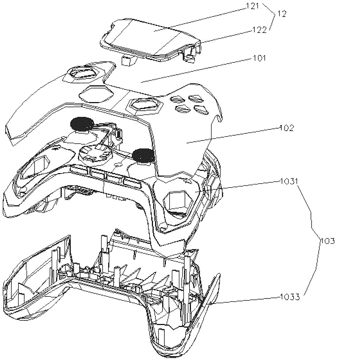
Refer toFIGS.1to3, which provide schematic diagrams of a game controller1according to the first embodiment of the present application. The game controller1includes a body100, a display screen assembly12arranged on the body100, and a gripping part13. Body100. The display screen assembly12is detachably mounted on the body100. In the embodiment, the gripping part13is positioned on one side of the game controller1, and the display screen assembly12is mounted on the other side of the body100from the side away from the gripping part13. When a user manipulates the game controller1, the game controller1is gripped by the user. In some other embodiments, the display screen assembly12may be mounted on the body100from either side of the game controller1.
The body100is provided with a mounting groove101for mounting the display screen assembly12. The body100includes a housing103, and a panel102detachably covered with the housing101. The panel102covers one surface of the housing103to form the front surface104of the body100. The housing103is provided with a button400, joysticks300, a wiring board (not shown), a processor, a battery, etc., so that the components of the game controller1are assembled together, and the function of the game controller is realized. In the embodiment, the housing103and the panel102are assembled together by magnetic attraction.
The housing103includes an upper shell1031and a lower shell1033that are detachably assembled together, and the housing103is a structural frame of the game controller, which ensures the stability and durability of the controller, and can not only protect internal circuits and assemblies, but also prevent the controller from external impact and damage. The setting of panel102provides a place for the game controller1to place the control buttons and control units. The buttons and control units may be arranged in the appropriate position. At the same time, it is also convenient for assembly and maintenance, and the detachable setting of the panel102makes the assembly and maintenance of the controller more convenient. When cleaning, component replacement, or repair is required, the panel102and the housing103can be easily removed to replace or repair assemblies such as internal circuits and connecting wires.
The gripping part13includes a symmetrical left gripping part (not shown) and a right gripping part (not shown). The left gripping part (not shown) and the right gripping part1(not shown) extend at intervals from one side105(rear end) of the housing103, so that a recessed part (not shown) is formed at a position between the left gripping part and the right gripping part at the rear end105, and the recessed part is opposed to the mounting groove101. The mounting groove101is opened from the front surface104of the body100to the other side106(i.e. front end) away from the gripping part13. The housing103is also provided with a plurality of mounting parts (not shown) at the position of the mounting groove101. Understandably, the position of the mounting groove103may change as the relative position of the display screen assembly12with respect to the body100changes according to actual setting needs. For example, when the display screen assembly12needs to be assembled from the left side of the body100, the position of the mounting groove103is positioned on the left side of body100; when the display screen assembly12needs to be assembled from the right side of the body100, the position of the mounting groove103is positioned on the right side of the body100.
Referring in conjunction withFIGS.4and5,FIGS.2and3are schematic views of the display screen assembly12of the first embodiment from two viewing angles, respectively, from the front and the back. The display screen assembly12is mounted on the body100through the mounting groove101. Specifically, in the embodiment, the display screen assembly12includes a display screen121and a bracket122. The display screen assembly12mounts the display screen121detachably on the body100through the bracket122. Further, when the display screen assembly12is mounted on the body100, the display screen12is arranged parallel to the front surface104, and the bracket122is mated and fixed with the body100. In the embodiment, the display screen12deviates from the middle position of the front surface104and is located on one side. In some other feasible embodiments, the display screen12is arranged in the middle position of the front surface according to the actual situation, that is, the above embodiment is only an example of the position of the display screen12.
The bracket122includes a cover plate1220, a side plate1222, and a mating part1224. The side plate1222extends downward from one end of the cover plate1220. The side plate1222is arranged opposite to the gripping part13. The cover plate1220includes a top surface1221and a back surface1223that are arranged opposite to each other. The display screen121is fixed on the back surface1223, and is covered by the cover plate1220and is closely integrated with the cover plate1220. The picture displayed by the display screen121is displayed through the cover plate1220. The displayed picture includes information for game status, menu options, character information, and the like. The side plate1222is also provided with a connector70through which the game controller1can be charged or communicated with the game console. When the display screen assembly12is mounted on the housing103, the cover plate1220and the side plate1222cover the mounting groove101so that the housing103forms a complete housing. Understandably, the side plate1222is arranged corresponding to one side of the body100according to the position of the display screen assembly12. For example, in the embodiment, the display screen assembly12is assembled on the front end side of the body100, and the side plate1222is provided corresponding to the front end of the body100, that is, is provided opposite to the gripping part13. If the display screen assembly12is assembled on the left side of the body100, the side plate1222is arranged corresponding to the left side of the body100. That is, it is merely an example that the side plate1222is arranged opposite to the gripping part13.
The display screen121is a touch-functional display screen or a touch screen with a touch function. The size of the display screen121may be set according to actual conditions, such as 2.8 inches, 3.2 inches, and so on. There is no limit here. The size of the cover plate1220is larger than that of the display screen121, and the display screen121is arranged in the middle position of the cover plate1220, so that additional protection and durability of the screen can be enhanced. The edge of the cover plate1220usually covers the frame body of the display screen121, so that the display screen121can be protected from collision and damage. The cover plate1220may be used to enhance the durability of the screen, prevent scratches, fingerprints, and other conditions that may cause damage to the screen in daily use. At the same time, the display screen121is in an area susceptible to impact and shock on the game controller, and the larger cover plate1220can provide better impact and shock resistance, reduce the risk of damage of the display screen121in movement or accidents, thereby prolonging its service life.
In the embodiment, the bracket122is all made of a material having a certain transparency, such as a transparent black material or a transparent plastic material. The transparent black material has a certain degree of transparency, can pass through a certain degree of light, and has a black appearance. The transparent black materials include fully transparent black material and translucent black material, for example, transparent black plastic material, transparent black glass material.
In some feasible embodiments, only the cover plate1220of the bracket122is made of light-transmitting material or a partial area of the cover plate1220is made of light-transmitting material, such as an area opposite the display screen121, so as to ensure that the picture displayed by the display screen121can be viewed.
The mating part1224is provided at intervals from the back surface1223and assembled with the mounting part, so as to preposition the bracket122with a display screen121, and fix the bracket122on the housing103through a fixing element (not shown). The fixing elements are bolts, screws, etc.
Refer in conjunction withFIGS.6and7, which are an overall schematic view and an exploded view, respectively, of the display screen assembly12′ of the second embodiment.
In the embodiment, the display screen assembly12′ also includes the display screen121′ and the bracket122′, but the bracket122′ of the display screen assembly12′ is different from the bracket122of the first embodiment in structure, and the assembly structure of the display screen121′ and the bracket122′ is also different from the assembly structure of the display screen121and the bracket1222of the first embodiment.
The bracket122′ includes a cover plate1220′, a side plate1222′, and a mating part1224′. The side plate1222′ extends vertically from one end of the cover plate1220′. The side plate1222′ is arranged opposite to the gripping part13. The cover plate1220′ includes a frame body1227with an opening12225and a top cover1229. The frame body1227includes an outer frame12270and a bottom frame12272extending from the bottom of the outer frame1227. The display screen121′ is supported by the bottom frame12272, and the top cover1229covers the display screen121′ and is surrounded by the outer frame1227. The top cover1229is made of a transparent black material. In the embodiment, the top cover1229is made of a glass material, that is, a glass panel. Further, the glass panel is a transparent black glass panel or a translucent black glass panel. The display screen121′ is bonded to the top cover1229by an adhesive. In the embodiment, the display screen121′ is a touch screen with a touch function.
In the above embodiments, the display screen is arranged on the bracket that is detachably mounted with the body, which is convenient to disassemble, repair, and replace through the bracket. At the same time, during transportation, it can be removed from the controller and the display screen assembly can be packaged separately to reduce damage during transportation.
In addition, the display screen assembly12is provided at the position of the game controller1away from the rear side edge of the gripping part13, which can provide the user with a better gaming experience and operation convenience. By placing the display screen assembly12in this position, the user can view important information in the game more conveniently, such as character attributes, maps, tasks, etc. At the same time, this position is close to the user's finger, which can help the user make corresponding operations more quickly and improve the real-time performance of the game. In addition, the placement of the display screen assembly12at the side edge position can also reduce the occlusion of the finger touch area, making the operation smoother. This allows the user to enjoy the game better without interfering the operation in game.
Refer toFIGS.3and8again, the upper shell1031is provided with a joystick300, the joystick300includes a joystick base and a joystick column, the joystick base is embedded in the upper shell1031and is fixed on the lower shell1033, the joystick column and the joystick base are detachably connected, the joystick column is exposed on the upper shell1031, the joystick300further includes a joystick head, and the joystick head is detachably connected to the top of the joystick column.
The joystick column is a core component of the joystick300and can detect finger movements and changes in direction. The joystick head is located at the top of the joystick column and is the area where the fingers are placed, usually a round or thumb-shaped button. The joystick base is the portion where the joystick column is inserted, holding the joystick300and providing stable support. The joystick300also includes a spring and a sensor, wherein the spring is located in the joystick base for adjusting the force of the joystick300to return to the center position, and the sensor is used to detect the force exerted by the finger on the joystick head.
The joystick head and the joystick column of the joystick300can be disassembled and replaced to facilitate maintenance and replacement, by disassembling and replacing the joystick head and the joystick column, the user can easily repair or replace worn or damaged parts. This can prolong the life of the controller and keep it in good operating performance.
At the same time, the disassembly and replacement of the joystick head and joystick column allows users to make personalized customization according to their own preferences and needs. They can choose joystick heads and joystick columns of different shapes, materials, specific sizes and friction to get an experience that is more in line with their feel and operating style. In this way, the replaceability of the joystick head and joystick column makes the game controller more versatile. For example, in different types of games, different joystick heads and joystick columns may be needed to provide more precise control, for example, a more sensitive joystick300is needed in a shooting game, a larger joystick head is needed in a racing game, etc. Users can make changes as needed to suit different gaming experiences.
Further, refer toFIGS.1to3, the joystick300includes a first joystick301and a second joystick302, the first joystick301is close to the left side of the display screen, the second joystick302is arranged on the front side of the display screen, and the connecting line between the first joystick301and the second joystick302is a diagonal line on the front.
This arrangement is due to the operational inertia of the user, and most users are accustomed to placing the main operating joystick300on the left-hand side, because the left hand is more flexible when controlling the game. Therefore, the first joystick301is usually arranged on the upper left side of the display screen121to provide the most intuitive and natural operating experience. In most games, the first joystick301is usually used for controlling important operations such as movement of a character and rotation of a viewing angle, while the second joystick302is used for auxiliary operations such as controlling a camera or performing special actions. Placing them in different areas of the display screen121makes the function and role operation of the two joysticks300more clear and avoids misoperation. The two joysticks do not interfere with each other, making it easier for the user to perform minor operations.
Refer toFIG.1again, the upper shell1031is further provided with the arrow keys400and a button set500, the arrow keys400and the second joystick302are arranged side by side on the same side of the display screen121; the button set500and the first joystick301are symmetrically arranged on both sides of the display screen121opposite to each other. The upper shell1031is further provided with a menu key600, and the menu key600is arranged on the rear side of the arrow keys400and the second joystick302.
In the embodiment, the arrow keys400and the button set500are used in combination to generate different key values corresponding to different functions. The arrow keys400are used to control the direction of the character or select menu options in the game, including up, down, left, and right directions. The button set500is used for various operations and interactions in the game. In the embodiment, the button set500has four buttons, the button set500is distributed in a cross shape, and the button set500is arranged into four buttons A, B, X, and Y in the game controller.
The menu key600of the game controller1is used to open the main game menu or navigation interface, so that the user can browse game options, settings, configurations of control units, etc. The game controller includes a pause/continue key, which is usually used in games to pause the game, allowing the user to pause the game progress or continue the game; further, a return key, which is used to return to the previous menu or close the current menu; and a multimedia control button, which is used to control multimedia functions, such as music playback, video pause, etc.
The above description is merely preferred embodiments of the present application, and is not intended to limit the present application. Any modifications, equivalent substitutions and improvements made within the principles of the present application shall be covered within the scope of protection of the present application.
Claims
- A game controller, comprising a body, a display screen assembly arranged on the body, and a gripping part arranged on the body, wherein the display screen assembly comprises a display screen and a bracket for mounting the display screen, and the display screen assembly detachably mounts the display screen on the body through the bracket;wherein the body is provided with a mounting groove, and the display screen assembly is assembled on the body through the mounting groove;the body comprises a front surface, and an opening of the mounting groove is opened from the front surface to a side surface of the body, when the display screen assembly is mounted on the body, the display screen is arranged parallel to the front surface, and the bracket is mated and fixed with the body;and the bracket comprises a cover plate, a side plate, and a mating part, and the side plate is arranged correspondingly to the side surface of the body;the cover plate comprises a top surface and a back surface that are opposite to each other;the display screen is mounted on the back surface of the cover plate and covered by the cover plate;the mating part is arranged at the back surface of the cover plate at intervals so as to be mated and fixed with the body, and a picture displayed on the display screen is displayed through the cover plate.
- The game controller according to claim 1, wherein the bracket is made of a transparent black material.
- The game controller according to claim 1, wherein the body comprises a housing and a panel, the panel is detachably mounted on the housing, and the panel is parallel to the display screen.
- The game controller according to claim 3, wherein the panel is suction-connected to the housing so that the panel is detachably mounted on the housing.
- A game controller, comprising a body, a display screen assembly arranged on the body, and a gripping part arranged on the body, wherein the display screen assembly comprises a display screen and a bracket for mounting the display screen, and the display screen assembly detachably mounts the display screen on the body through the bracket;wherein the body comprises a housing and a panel, the panel is detachably mounted on the housing, and the panel is parallel to the display screen;and the panel is suction-connected to the housing so that the panel is detachably mounted on the housing.
Disclaimer: Data collected from the USPTO and may be malformed, incomplete, and/or otherwise inaccurate.