Illustrative Figure
Abstract
A game console storage base configured to store a game console and dissipate heat from the game console, wherein the game console storage base comprises: a housing configured to accommodate the game console and comprising an air inlet, wherein the air inlet is configured to facilitate dissipating heat from the game console into an interior of the housing; at least one heat dissipation fan arranged in the interior of the housing, wherein the at least one heat dissipation fan discharges heat from the interior of the housing to an external of the housing; at least one temperature sensor configured to sense a temperature of the game console; and a control circuit connected to the at least one temperature sensor and the at least one heat dissipation fan.
Description
DETAILED DESCRIPTION The present disclosure provides a game console storage base100adapted to storing and cooling a game console200and configured to charge a handle controller (not shown in the figures) of a game machine. Specific configuration of a game console storage base100of each embodiment is described in detail below. First Embodiment Referring toFIGS.1to4, the configuration of a game console storage base100of the present embodiment is described in detail. The game console storage base100of the present embodiment includes a housing10, and a heat dissipation unit109, a temperature sensor60and a control circuit80which are installed on the housing10. As shown inFIGS.1and2, the housing10is roughly in a shape of a long box, and is enclosed and formed by a top surface105and a bottom surface106which are opposite to each other (refer toFIGS.3,5and6) and four side surfaces101-104. On the top surface105of the housing10, an accommodation groove19is formed in an inwardly recessed manner, to store the game console200. The accommodation groove19includes a bottom wall191and a side wall192connected with the bottom wall191, and the side wall192of the accommodation groove19is connected with a groove outer wall1051of a region outside of the accommodation groove19in the top surface105of the housing10. The recessed shape of the accommodation groove19is matched with the contour of an end surface on one side of the game console200, so that the game console200is clamped by the bottom wall191and the side wall192. In addition, not limited thereto, the shape of the accommodation groove19can be changed according to the contour of the game console200. The heat dissipation unit109is arranged on the housing10and is configured to dissipate heat from the game console200. In the present embodiment, the heat dissipation unit109includes a first fan20and a heat dissipation channel21. The heat dissipation channel21is formed by communicating an air inlet15and an air outlet16which are formed on the housing10. The air inlet15is formed by penetrating ...
DETAILED DESCRIPTION
The present disclosure provides a game console storage base100adapted to storing and cooling a game console200and configured to charge a handle controller (not shown in the figures) of a game machine. Specific configuration of a game console storage base100of each embodiment is described in detail below.
First Embodiment
Referring toFIGS.1to4, the configuration of a game console storage base100of the present embodiment is described in detail. The game console storage base100of the present embodiment includes a housing10, and a heat dissipation unit109, a temperature sensor60and a control circuit80which are installed on the housing10.
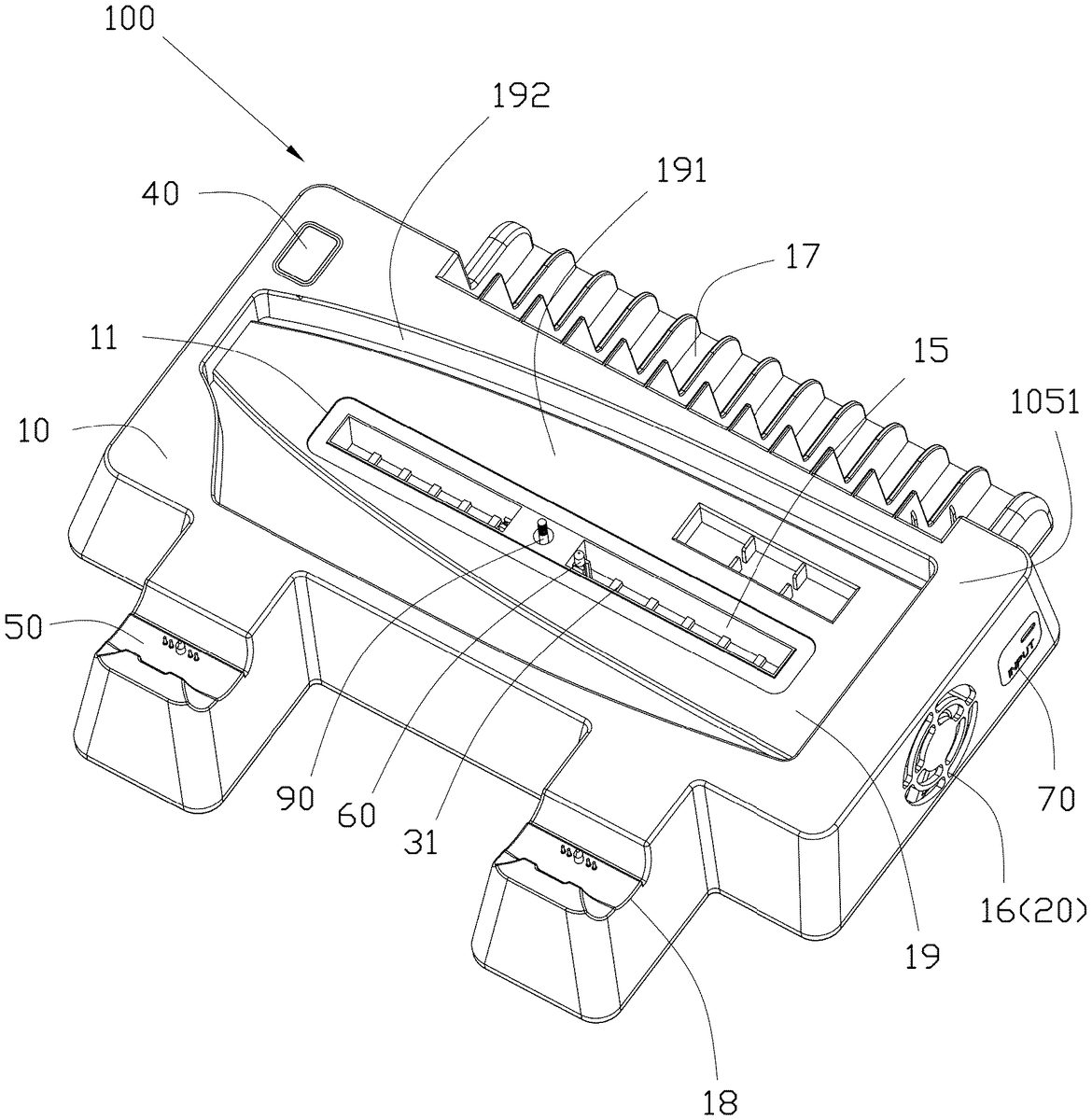
As shown inFIGS.1and2, the housing10is roughly in a shape of a long box, and is enclosed and formed by a top surface105and a bottom surface106which are opposite to each other (refer toFIGS.3,5and6) and four side surfaces101-104. On the top surface105of the housing10, an accommodation groove19is formed in an inwardly recessed manner, to store the game console200. The accommodation groove19includes a bottom wall191and a side wall192connected with the bottom wall191, and the side wall192of the accommodation groove19is connected with a groove outer wall1051of a region outside of the accommodation groove19in the top surface105of the housing10. The recessed shape of the accommodation groove19is matched with the contour of an end surface on one side of the game console200, so that the game console200is clamped by the bottom wall191and the side wall192. In addition, not limited thereto, the shape of the accommodation groove19can be changed according to the contour of the game console200.
The heat dissipation unit109is arranged on the housing10and is configured to dissipate heat from the game console200. In the present embodiment, the heat dissipation unit109includes a first fan20and a heat dissipation channel21.
The heat dissipation channel21is formed by communicating an air inlet15and an air outlet16which are formed on the housing10. The air inlet15is formed by penetrating through the bottom wall191of the accommodation groove19at the accommodation groove19, and the air inlet15is communicated with a heat dissipation surface of the game console200, to allow entrance of heat from the game console200into the heat dissipation channel21inside the game console storage base100. In addition, the number of openings of the air inlet15can be multiple, and can be set appropriately according to actual needs. The air outlet16penetrates through a first side surface101of the plurality of side surfaces101-104connected with the top surface105of the housing10. The air outlet16communicates to the exterior and is communicated with the air inlet15, such that the heat dissipation channel21communicating the air inlet15and the air outlet16is formed inside the housing10. Therefore, heat exhausted out of the game console200is brought in from the air inlet15by the first fan20(hereafter also called a heat dissipation fan) to form airstreams (also called hot air)301in the heat dissipation channel21, and the hot air301is discharged from the air outlet16under the drive of the airstreams302formed by the fan20. Directions of the airstreams302is kept consistent relative to directions of hot air301exhausted out of the game console, as a result, the first fan20discharges heat from the interior of the housing10to an external of the housing10. Therefore, heat dissipated by the game console200can be carried away quickly and the game console is cooled efficiently. In addition, preferably, at least part of the heat dissipation channel21is formed as a cavity, such that heat can be carried away without interfering with the flow of the airs.
The temperature sensor60can be arranged in the air inlet15at the accommodation groove19of the housing10as shown inFIG.1, so that the temperature sensor60contacts or is close to the heat dissipation surface, which dissipates heat, of the game console200. Preferably, the temperature sensor60can be configured in a manner of partially protruding from the air inlet15, so that the temperature sensor60is closer to the heat dissipation surface or directly contacts the heat dissipation surface of the game console200, and thus can detect the temperature of the heat dissipation surface of the game console200at a high accuracy.
The control circuit80is arranged on the housing10and is connected with the temperature sensor60and the first fan20to receive temperature values fed back by the temperature sensor60, and controls operation of the first fan20and adjusts the rotational speed of the first fan20. The temperature sensor60monitors, in real time, heat dissipation temperature of the game console, to provide a basis for heat dissipation control of the game console. The control circuit80can be configured as follows: for example, a first threshold indicating overheating of the game console200can be set. In the case where the fan is not turned on, when the temperature sensor60detects that the temperature reaches or exceeds the first threshold, the control circuit80enables the first fan20to operate to cool the game console200. In addition, in the case where the first fan20is turned on, when the temperature sensor60detects that the temperature reaches or exceeds the first threshold, the control circuit80increases the rotational speed of the first fan20, thereby improving the heat dissipation effect. Moreover, a second threshold indicating that heat dissipation of the game console200is acceptable can also be set. When the temperature sensor60detects that the temperature is lower than the second threshold, the control circuit80lowers the air speed of the first fan20or turns off the first fan, and the air speed of the first fan20is adjusted with the heat dissipation temperature of the game console200as a reference, such that noise generated due to excessive operation of the first fan20can be suppressed, and therefore, the user experience is improved while the heat dissipation effect is not influenced. In other examples, adjustment of the rotational speed of the fan can be independent from the setting of the temperature threshold, in other words, replacing an automatic adjustment method based on temperature thresholds, manual adjustment can be performed.
In the present embodiment, according to the above configuration, the heat dissipation efficiency of the game console storage base100can be adjusted according to actual heat generation of the game console200, and the first fan20is operated at a proper rotational speed, such that noise generated due to excessive operation of the first fan20can be suppressed while a sufficient heat dissipation effect is ensured, and the user experience is better.
In addition, the game console storage base100of the present embodiment can further include a display part40. The display part40is connected with the control circuit80, and the control circuit80is connected with one or more temperature sensors60. The temperature sensor60detects a temperature value, and the temperature value detected by the temperature sensor60can be displayed by the display part40connected with the control circuit80. The display part40may be a display device, for example, a digital tube, a liquid crystal display or a projector. In addition, the configuration of the present application is not limited thereto, and the display part40may also be an indicator light. For example, temperature degree information may also be denoted by using a gear indicated by the indicator light. In addition, the configuration of the present application is not limited thereto, and the above information may be displayed in the same display part40, and may also be separately displayed in different display parts. In addition, the configuration of the present application is not limited thereto, and a display part40having both a display screen and an indication part may also be used. Such a display part40having both a display screen and an indication part can be formed integrally or separately. For example, the housing includes a display screen40on one surface, and includes an indication part on another surface.
In addition, the game console storage base100can also be further provided with an adjustment part, for example, a button, configured to adjust the air speed, and a switch button of the first fan20and other operation parts operated by a user with instructions for controlling fans (including the first to the fourth fans20,22,24,26), and a part12can also be configured to include a button and other operation parts. For example, in examples as shown inFIG.2, etc., the game console storage base100includes a display part40, and a part12displaying information different from that displayed by the display part40. The display part40is arranged on the top surface105, and the control circuit80is connected with the display part40and the temperature sensor60. Based on the temperature detected by the temperature sensor60, the display part40displays the value of the temperature. The part12is arranged on the second side surface102, and the part12is connected with the control circuit80and the first fan20to control and display the rotational speed of the fan. The positions of the display part40and the part12are not limited thereto and can be set according to actual needs.
In addition, in the game console storage base100, the bottom surface106can also include a radiation fin13. By providing the radiation fin13, the radiation fin13preferably including a material with excellent thermal conductivity, the heat radiation effect can be improved. The entire bottom surface106of the housing10may be constituted by the radiation fin13. However, it can be understood that, in the present disclosure, part of the bottom surface may be constituted by the radiation fin13, the specific shape of which is not limited, and the radiation fin13may also be omitted.
In addition, in the case where the heat dissipation channel21of the housing10is formed to be relatively large, air easily diffuses around, and cannot quickly carry heat out of the air outlet16via the first fan20, such that heat is accumulated in the internal space, and the heat dissipation effect will be influenced over time.
Preferably, inside the housing10, one or more baffle plates14for narrowing the heat dissipation channel21may also be included. For example, as shown inFIGS.3and4, three baffle plates14are provided. The three baffle plates14are erected from the bottom surface106of the housing10to the top surface105of the housing10. The three baffle plates14, the top surface105, the first side surface101and the bottom surface106of the housing10enclose a tunnel-shaped space which serves as the heat dissipation channel21. One of the three baffle plates14is opposite to the first side surface and is formed at an end, far away from the first side surface, of the air inlet15, and the other two baffle plates are opposite to each other with the air inlet15being sandwiched therebetween. One or more baffle plates14can narrow the space in which air flows, such that an appropriate amount of heat is more easily carried out of the housing. However, it can be understood that, the number and positions of the baffle plates14are not limited to the structures shown inFIGS.3and4, and can be appropriately changed according to actual needs. For example, each baffle plate14may be constituted by a flat plate, and may also be constituted by a curved plate, and the one or more baffle plates14may also include both a flat baffle plate14and a curved baffle plate14. In addition, one baffle plate14may be a continuous and integrated baffle plate14, and in this way, the one baffle plate14, the first side surface101, the top surface105and the bottom surface106enclose and form the heat dissipation channel21. In addition, it is also possible that multiple baffle plates14and the first side surface101together enclose and form a polygon with sides formed thereby, to form the heat dissipation channel21, which is formed into a polygon in a top view. Therefore, the inside of the game console200is only communicated with the heat dissipation channel21in the housing10, and the heat dissipation channel21provides a tunnel-shaped airflow channel for air, and air can be quickly carried out of the air outlet16via the first fan20, thereby suppressing accumulation of heat in the internal space, and improving the heat dissipation effect.
In addition, in order to centralize air entering from the air inlet15of the housing10, preferably, an air collection part30is arranged at the air inlet15. The air collection part30is like a tub, open at top and bottom, extending towards the inside of the housing10from the air inlet15, such that air carrying heat from the game console200enters the inside of the housing10in a manner of being centralized to the middle of the housing10by the air collection part30, thereby reducing diffusion of air in the internal space of the housing10, and improving the heat dissipation effect. However, it can be understood that the air collection part30may be omitted.
In addition, storage parts are arranged at two opposite side surfaces of the housing10in a width direction, that is, the third side surface103and the fourth side surface104inFIG.1, etc. For example, as shown inFIG.1, an optical disc storage part17can be formed in the third side surface, and a handle storage part18can also be formed in the fourth side surface in a manner of protruding outwards. The optical disc storage part17is provided with a plurality of slots7, and the plurality of slots7are arranged along a long side of the game console storage base100to store game optical discs. A groove is formed in the handle storage part18to store a handle. In addition, a charging part50may also be provided inside the handle storage part18, and a charging terminal or a charging interface is provided inside the charging part50. Therefore, the game console storage base100of the present disclosure can not only dissipate heat from the game console200stored thereon, but also can charge the handle stored thereon.
In addition, the housing10can also include an interface part70including at least any one of a USB interface or the like configured to charge an external electronic device, and an external power interface configured to charge the game console storage base100.
[Modification of the First Embodiment]
In addition, the first fan20in the heat dissipation unit109may also be arranged close to the second side surface102on an opposite side with respect to the first side surface101. Through blowing air to the heat dissipation channel21by the first fan20, an airstream flowing from the air inlet15to the air outlet16is provided, such that heat in the game console storage base100is rapidly discharged.
In addition, the heat dissipation unit109can include one or more first fans20. In addition, other side surfaces, except the first side surface101, of the four side surfaces101-104in the above embodiment are configured to be closed, so as to provide, in the internal space of the housing10, a relatively closed airflow channel for air. However, the present disclosure is not limited thereto. For example, the second side surface102may also be non-closed as shown inFIGS.5and6. Specific configuration of the heat dissipation unit109is described specifically as follows.
For example, as shown inFIG.5, the heat dissipation unit109includes an air inlet15, a first air outlet16, a second air outlet161, a first fan20and a second fan22. The first air outlet16is formed on the first side surface101, the second air outlet161is formed on the second side surface102, the first fan20is arranged close to the first air outlet16, that is, the side of the first side surface101, so as to provide, in the heat dissipation channel21, airstreams301flowing from the air inlet15towards the first air outlet16, and the second fan22(hereafter also called a heat dissipation fan) is arranged close to the second air outlet161, that is, the side of the second side surface102, to provide, in the heat dissipation channel21, airstreams301flowing from the air inlet15towards the second air outlet161. In this way, Directions of the airstreams302,303is kept consistent relative to directions of hot air301exhausted out of the game console, as a result, heat in the heat dissipation channel21can be further rapidly carried out of the housing10, and the heat dissipation effect is further improved.
In addition, the heat dissipation unit109may also, for example as shown inFIG.6, include an air inlet15, an air outlet16, an air suction port162, a first fan20and a third fan24. The air outlet16is formed on the first side surface101, the air suction port162is formed on the second side surface102, the first fan20is arranged close to the air outlet16, that is, the side of the first side surface101, to provide, in the heat dissipation channel21, airstreams1301flowing from the air inlet15towards the air outlet16, and the third fan24(hereafter also called a heat dissipation fan) is arranged close to the air suction port162, that is, the side of the second side surface102, to provide, in the heat dissipation channel21, airstreams2301flowing from the air suction port162towards the air outlet16. In this way, directions of the airstreams1302,1303is kept consistent relative to directions of hot air1301,2301exhausted out of the game console, as a result, heat in the heat dissipation channel21can be further rapidly carried out of the housing10, and the heat dissipation effect is further improved.
In addition, the game console storage base100can further include a fourth fan26(hereafter also called a heat dissipation fan) and an installation part261for fixing the fourth fan26(refer toFIGS.10-12). The fourth fan26is arranged to be corresponding to a surface, which is provided with air inlet holes, of the game console200, to provide extra airstreams304whose directions is kept consistent relative to the directions of airstreams (also called inlet air)305inside the game console flowing into the game console200, thereby improving the heat dissipation effect.
Installation Example of the First Embodiment
A game console200of Sony PS5 is used as an example below to describe some examples of the installation manner of the game console200and the game console storage base100of the present embodiment.
Firstly, rough configuration of the game console200is described. As shown inFIG.13, a top surface220of the game console200is also provided with a plurality of air inlet holes221for air intake; a back surface230of the game console200is generally provided with an external power interface and a data transmission interface, etc., and is also provided with a plurality of heat dissipation holes231configured to discharge heat inside the game console200; a bottom surface240of the game console200is provided with a plurality of heat dissipation holes241and a fixing hole243; the plurality of heat dissipation holes241are also configured to discharge heat inside the game console200, and the fixing hole243is formed by penetrating through the housing201at the bottom of the game console200, to fix the game console200; a fan290for heat dissipation is arranged in the interior of the game console200, thereby forming a console heat dissipation channel270of flowing from a plurality of air inlet holes211and a plurality of air inlet holes221towards a plurality of heat dissipation holes231and a plurality of heat dissipation holes241. Therefore, the game console200generally includes two air inlet surfaces provided with air inlet holes211and221and two heat dissipation surfaces provided with heat dissipation holes231and241.
When the game console200is stored in game console storage base100, the game console can be stored in the accommodation groove19in such a manner that the bottom surface240is in contact with the game console storage base100, the game console can also be stored in the accommodation groove19in such a manner that the back surface230is in contact with the game console storage base100, or the game console can be stored in the accommodation groove19in such a manner that one side surface250is in contact with the game console storage base100. However, no matter which part is in contact with the game console storage base100when the game console is stored, through appropriate design, the game console storage base100allows the game console200to be stored vertically, and also allows the game console200to be stored horizontally.
In addition, in order to prevent the game console200from titling when the game console is vertically stored for example, a fixing part90can be arranged in the accommodation groove19. The fixing part90includes a fastener such as a screw and a base for supporting the fastener. By connecting and tightly locking the fastener and the fixing hole243of the game console200, the game console200can be fixed in the game console storage base100by means of the bottom surface240. In embodiments ofFIG.1, etc., the fixing part90corresponds to the fixing hole243arranged in the center of the bottom surface240of the game console200, and is arranged in the center of the accommodation groove19and is in the air inlet15, such that two air inlets15are formed, extending along a length direction of the housing10. However, the present disclosure is not limited thereto. The fixing part90may also be not arranged in the center of the accommodation groove19and in the air inlet15, and changes can be made appropriately according to accommodation postures of the game console200. For example, in the example ofFIG.12, the fixing part90can be arranged in the side wall192of the accommodation groove19, as long as the fixing part90can be relatively fixed relative to the bottom surface240of the game console200. In addition, in the case where the game console200is stored horizontally, the fixing part90can also be omitted.
As shown inFIG.8, the placement orientation of the game console is shown in the lower right corner. When the bottom surface240of the game console200is installed and stored towards the top surface105of the game console storage base100, for example, when the game console200is stored vertically, the game console200can be stably stored by means of the fixing part90. In addition, through appropriate changes, the game console200can be stored horizontally, as long as the console heat dissipation channel270of the game console200is communicated with the heat dissipation channel21in the housing10. In addition, a gasket11surrounding the air inlet15can be arranged on the top surface105of the housing10(refer toFIG.1, etc.). As an example, the gasket11can be formed by a sealing material such as rubber. However, it can be understood that in the present disclosure, the gasket11can also be omitted.
In the case of vertical storage, on the top surface105of the game console storage base100, the bottom wall191of the accommodation groove19is arranged to contact the bottom surface240, which is one main heat dissipation surface of the game console200, a plurality of air inlets15can be arranged appropriately corresponding to a plurality of heat dissipation holes241of the game console200, and the side wall192of the accommodation groove19is close to or contacts the game console200. Therefore, heat of the game console200also flows through the entire accommodation groove19and the air inlet15. Moreover, the groove outer wall1051is provided with an outer groove heat flowing region107athrough which heat of the game console200also flows. Hot air carrying heat blown out from part of the region of the back surface230, which is another main heat dissipation surface of the game console200, flows through the outer groove heat flowing region107a. Therefore, the top surface105is formed with a heat flowing region107containing the air inlet15, the bottom wall191and the side wall192of the accommodation groove19and part of the groove outer wall1051as shown inFIG.7. In other words, the game console storage base100can receive, in the heat flowing region107, heat dissipated by the game console200.
In examples ofFIGS.1to4, the temperature sensor60is installed on the base of the fixing part90, therefore, additional setting of an installation part configured to fix the temperature sensor60is avoided, and the fixing part90has both functions of fixing the fastener and the temperature sensor60. In addition, the present disclosure is not limited thereto, and the temperature sensor can be arranged at any position in the heat flowing region107of the game console storage base100, that is, at any of the air inlet15, the bottom wall191and the side wall192of the accommodation groove19, and the outer groove heat flowing region107aof the groove outer wall1051. In the case where the temperature sensor is arranged at the bottom wall191or the side wall192, a mounting groove or a hole may be formed at a position where the temperature sensor60is installed, to avoid that the temperature sensor60hinders installation of the game console200into the accommodation groove19. In addition, in examples ofFIGS.1to4, one temperature sensor60is arranged in the air inlet15. However, the present embodiment is not limited thereto, and a plurality of temperature sensors60may be arranged.
In addition, the temperature sensor60may also be arranged at other positions in the heat dissipation channel21. As shown inFIG.8, the temperature sensor60can be at least any one of a first temperature sensor61installed in the air inlet15, a second temperature sensor62arranged in the bottom surface106and a third temperature sensor63arranged close to the air outlet16, and the first to third temperature sensors61-63are connected with the control circuit80. Preferably, only one first temperature sensor61is utilized to detect the temperature of the game console200, so that the heat dissipation condition of the game console is conveniently acquired by a user through display by the display part40, or the heat dissipation efficiency of the game console by the game console storage base100is adjusted through control by the control circuit80.
In addition, also as shown inFIG.9, a temperature sensor which is arranged to be opposite to part of the back surface230of the game console200can further be included. For example, at least any one of a fifth temperature sensor65arranged on the side wall192and a sixth temperature sensor66arranged on the groove outer wall1051is included, and the first, fifth and sixth temperature sensors61,65,66are connected with the control circuit80. The fifth and sixth temperature sensors65,66are arranged corresponding to a heat dissipation surface, for example, the back surface230, of the game console, such that the fifth and sixth temperature sensors65,66can sense heat dissipated from the heat dissipation holes231of the back surface230.
In addition, in the case where the temperature sensor60includes a plurality of temperature sensors, the control circuit80increases the heat dissipation efficiency of the heat dissipation unit109when the temperature detected by any one of the plurality of temperature sensors reaches a first threshold indicating overheating of the game console200, and reduces the heat dissipation efficiency of the heat dissipation unit109when the temperatures detected by all the plurality of temperature sensors drop to a second threshold indicating that heat dissipation of the game console200is completed.
In addition, in the case where a fourth fan26is further included, the game console200can be stored horizontally, and can also be stored vertically. For example, the fourth fan26is opposite to the air inlet holes221of the top surface220of the game console200, and blows air towards the inside of the game console200, so as to improve the heat dissipation efficiency of the game console200. Moreover, the air inlet15is communicated with the heat dissipation holes241of the bottom surface240of the game console200, and brings heat inside the game console200into the game console storage base100. The fourth fan26is communicated with an air flowing-in end of the console heat dissipation channel270in the game console200, and at least the first fan20is communicated with an air flowing-out end of the console heat dissipation channel270in the game console200, so as to achieve rapid heat dissipation of the game console200. Moreover, as long as the fourth fan26is connected with the flowing-in end of the console heat dissipation channel270in the game console200, and the heat dissipation unit109in the housing10is connected with the flowing-out end of the console heat dissipation channel270, other configuration can be changed according to actual needs.
In addition, in addition to a first housing110in which the heat dissipation channel21is arranged, the housing10of the game console storage base100further includes a second housing120for fixing the fourth fan26. The second housing120may be a clamping piece to be clamped on the game console200, and may also be a supporting piece which is arranged on one surface to support the fourth fan26. In addition, the second housing120may be integrated with the first housing110, or they may be connected with each other or may be separated from each other.
In addition, inFIGS.10and11, the temperature sensor arranged in the heat dissipation channel21includes any one of the above-mentioned first to third temperature sensors61-63, to detect heat dissipated from the bottom240of the game console200. In addition, the temperature sensor can also include any one of the fifth temperature sensor65which is opposite to part of the back surface230of the game console200and which is arranged on the side wall192and the sixth temperature sensor66arranged on the groove outer wall1051.
In addition, the game console200can also be stored horizontally as shown inFIG.12, such that the game console is stored in the accommodation groove19in such a manner that one side surface250is in contact with the game console storage base100. In this case, the air inlet15is connected with the side surface250of the game console200, to allow entrance of heat dissipated from the side surface250. The temperature sensor in the heat dissipation channel21can include any one of the above-mentioned first to third temperature sensors61-63. In addition, the temperature sensor can also include any one of the fifth temperature sensor65which is opposite to part of the back surface230or the bottom surface240of the game console200and which is arranged on the side wall192and the sixth temperature sensor66arranged on the groove outer wall1051. In addition, the fixing part90may also be arranged according to the horizontal posture of the game console200, in such a manner that the fixing part90for fixing the game console200is arranged on the side wall192opposite to part of the bottom surface240of the game console200, and the temperature sensor60is also positioned in the fixing part90, which can also achieve the same effect as in the case of vertical storage.
In addition, heat dissipation fans can also be used as the first to fourth fans20,22,24,26of the present application.
Claims
- A game console storage base configured to store a game console, and dissipate heat from the game console, wherein the game console storage base comprises: a housing configured to accommodate the game console and comprising an accommodation groove recessed inwardly, and an air inlet disposed in the accommodation groove, wherein the air inlet is configured to facilitate dissipating heat from the game console into an interior of the housing;at least one heat dissipation fan arranged in the interior of the housing, wherein the at least one heat dissipation fan discharges heat from the interior of the housing to an external of the housing;at least one temperature sensor configured to sense a temperature of the heat dissipated from the game console;and a control circuit connected to the at least one temperature sensor and the at least one heat dissipation fan, wherein the housing further comprises a fixing part configured for fixing the game console on the game console storage base and disposed in the air inlet, and the at least one temperature sensor comprises a first temperature sensor which is arranged at the fixing part.
- The game console storage base according to claim 1, wherein the fixing part comprises a first surface adjacent to a first heat dissipation surface of the game console, the first temperature sensor is arranged on the first surface of the fixing part.
- The game console storage base according to claim 1, wherein the housing further comprises a heat dissipation channel in the interior of the housing and a first air outlet on the housing, the air inlet and the first air outlet communicates with the heat dissipation channel, and the first air outlet communicates to the exterior of the housing, thereby discharging heat to the exterior of the housing.
- The game console storage base according to claim 3, wherein the at least one heat dissipation fan comprises a first heat dissipation fan arranged in the interior of the housing, and the first heat dissipation fan is configured to provide airstreams flowing into the heat dissipation channel and then to the external of the housing.
- The game console storage base according to claim 4, wherein the first heat dissipation fan is arranged adjacent to the first air outlet.
- The game console storage base according to claim 4, wherein the first heat dissipation fan is arranged away from the first air outlet, opposite to the first air outlet, in the interior of the housing.
- The game console storage base according to claim 4, wherein directions of the airstreams formed by the first heat dissipation fan is kept consistent relative to directions of hot air exhausted out of the game console.
- The game console storage base according to claim 4, wherein the game console storage base further comprises a second heat dissipation fan, which is arranged adjacent to air inlet holes of the game console, and directions of airstreams formed by the second heat dissipation fan is kept consistent relative to the directions of inlet air of the game console.
- The game console storage base according to claim 3, wherein the at least one temperature sensor comprises a second temperature sensor which is arranged adjacent to the first air outlet.
- The game console storage base according to claim 1, wherein the accommodation groove comprises a bottom wall and a side wall connected with the bottom wall, and the air inlet is located on the bottom wall.
- The game console storage base according to claim 1, wherein the game console storage base further comprises: a handle controller charging part configured to charge a handle controller;an indication part indicating a charging state of the handle controller and indicating an operating state of the at least one heat dissipation fan;and an operation part connected with the control circuit and the at least one heat dissipation fan and configured to control the operating state of the at least one heat dissipation fan.
- The game console storage base according to claim 1, wherein the game console storage base further comprises a display part, wherein the display part is connected with the control circuit and configured to display the value of the temperature detected by the at least one temperature sensor.
- The game console storage base according to claim 12, wherein the game console storage base further comprises an operation part connected with the control circuit and the at least one heat dissipation fan and configured to control an operating state of the at least one heat dissipation fan by the control circuit, and when the operation part is operated, the operation part sends instructions to the control circuit, such that the control circuit adjusts a rotational speed of the at least one heat dissipation fan.
- The game console storage base according to claim 1, wherein the first heat dissipation surface of the game console comprises a plurality of heat dissipation holes, and the first temperature sensor is arranged to be adjacent to at least part of the heat dissipation holes.
- The game console storage base according to claim 1, wherein the control circuit is configured to adjust a rotational speed of the at least one heat dissipation fan according to the value of the temperature detected by the at least one temperature sensor, and the higher the value of the temperature, the higher the rotational speed of the heat dissipation fan.
- The game console storage base according to claim 1, wherein the control circuit is configured to: increase the heat dissipation efficiency of the at least one heat dissipation unit when the temperature detected by any one of the at least one temperature sensor reaches a first threshold indicating overheating of the game console;and reduce the heat dissipation efficiency of the at least one heat dissipation unit when the temperature detected by all of the at least one temperature sensor drops a second threshold indicating that heat dissipation of the game console is completed, the first threshold is higher than the second threshold.
- A game console storage base configured to store a game console, and dissipate heat from the game console, the game console having a plurality of air inlet holes, wherein the game console storage base comprises: a housing configured to accommodate the game console, and comprising an air inlet configured to facilitate dissipating heat from the game console into an interior of the housing;at least one heat dissipation fan configured for discharging heat of the game console, at least one temperature sensor configured to sense a temperature of the heat dissipated from the game console;and a control circuit connected to the at least one temperature sensor and the at least one heat dissipation fan, wherein the at least one heat dissipation fan comprises a first heat dissipation fan arranged in the interior of the housing and configured for discharging heat from the interior of the housing to an external of the housing;and a second heat dissipation fan arranged adjacent to the air inlet holes of the game console, and directions of airstreams formed by the second heat dissipation fan is kept consistent relative to directions of inlet air of the game console.
- A game console storage base configured to store a game console, and dissipate heat from the game console, and mount the game console by a first engagement element configured, wherein the game console storage base comprising: a housing configured to accommodate the game console, and comprising an air inlet configured to facilitate dissipating heat from the game console into an interior of the housing;at least one heat dissipation fan arranged in the interior of the housing, wherein the at least one heat dissipation fan discharges heat from the interior of the housing to an external of the housing;at least one temperature sensor configured to sense a temperature of the heat dissipated from the game console;and a control circuit connected to the at least one temperature sensor and the at least one heat dissipation fan;and wherein a second engagement element is provided in the air inlet, the second engagement element engages with the first engagement element of the game console to fix the game console into the game console storage base, the at least one temperature sensor comprises a first temperature sensor which is arranged at the second engagement element.
Disclaimer: Data collected from the USPTO and may be malformed, incomplete, and/or otherwise inaccurate.