U.S. Pat. No. 12,194,375
Game Controller
Issue DateNovember 11, 2021
Illustrative Figure
Abstract
A game controller for controlling the play of computerized games and other related control systems includes a plurality of pressure sensitive touch controls, capacitive controls, and touch pad controls which are configured to initiate commands and perform other desired operations and functions. The sensitivity of the controls can be adjusted and their function can be programmed and customized.
Description
DETAILED DESCRIPTION Detailed descriptions of specific embodiments of the game controller and its actuator mechanisms and other features are disclosed herein. It can be readily understood that the disclosed embodiments are merely examples of the way in which certain aspects of the invention can be implemented and do not represent all of the ways the invention may be embodied. The game controller and its actuator mechanisms and other features described herein may be embodied in various alternative forms. Further, the drawing figures are not necessarily to scale and some features may be enlarged or minimalized to show certain details and features of particular embodiments. Some well-known structures, components, features, materials, and methods are not necessarily described in great detail for the sake of brevity and in order to focus upon the present invention. Any specific structural and functional details disclosed herein are not to be interpreted as limiting, but rather are provided for teaching one skilled in the art to variously employ the invention, and as basis for the claims. FIG.1is a top view of a game controller1according to one embodiment including a left thumbstick control11and a right thumbstick control12located asymmetrically relative to the left handle portion4, the middle portion3, and the right handle portion5of the game controller1similar to the Microsoft Xbox One® game controller which is believed to be represented in U.S. D709,882 S by Morris et al. The embodiment of a game controller1shown inFIG.1includes a case2having a front side21, back side22, top side23, bottom side24, left side25, right side26, left shoulder portion6, a right shoulder portion7, a middle portion3, a left handle portion4, and a right handle portion5. As shown, the top view of the controller1shows an on and off control8, a left selection control14which can be used as a back control switch and for other functions, a ...
DETAILED DESCRIPTION
Detailed descriptions of specific embodiments of the game controller and its actuator mechanisms and other features are disclosed herein. It can be readily understood that the disclosed embodiments are merely examples of the way in which certain aspects of the invention can be implemented and do not represent all of the ways the invention may be embodied. The game controller and its actuator mechanisms and other features described herein may be embodied in various alternative forms. Further, the drawing figures are not necessarily to scale and some features may be enlarged or minimalized to show certain details and features of particular embodiments. Some well-known structures, components, features, materials, and methods are not necessarily described in great detail for the sake of brevity and in order to focus upon the present invention. Any specific structural and functional details disclosed herein are not to be interpreted as limiting, but rather are provided for teaching one skilled in the art to variously employ the invention, and as basis for the claims.
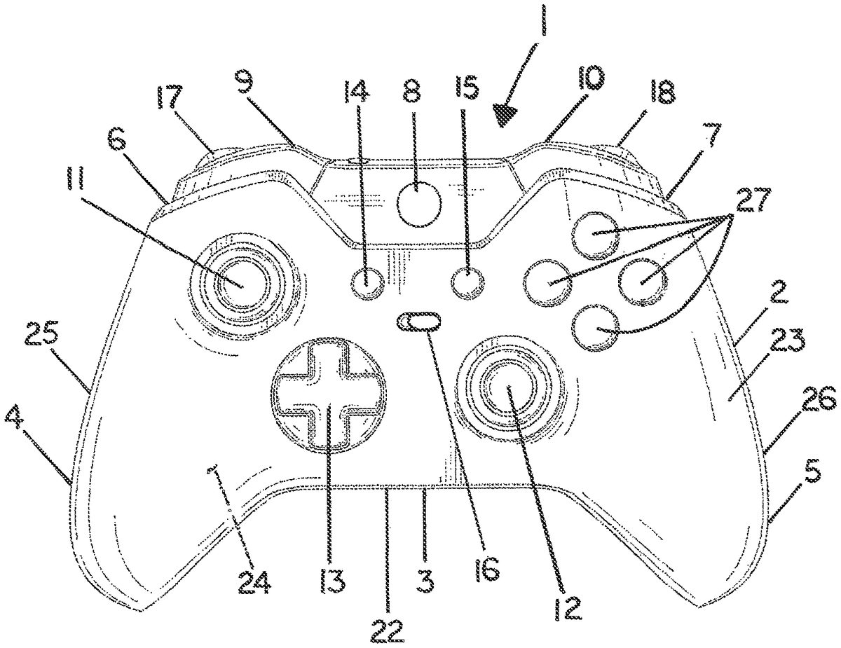
FIG.1is a top view of a game controller1according to one embodiment including a left thumbstick control11and a right thumbstick control12located asymmetrically relative to the left handle portion4, the middle portion3, and the right handle portion5of the game controller1similar to the Microsoft Xbox One® game controller which is believed to be represented in U.S. D709,882 S by Morris et al. The embodiment of a game controller1shown inFIG.1includes a case2having a front side21, back side22, top side23, bottom side24, left side25, right side26, left shoulder portion6, a right shoulder portion7, a middle portion3, a left handle portion4, and a right handle portion5. As shown, the top view of the controller1shows an on and off control8, a left selection control14which can be used as a back control switch and for other functions, a right selection control15which can be used as a menu control switch and for other functions, a mapping preset control16for changing between a plurality of mapping presets, a left trigger control9and a left bumper control17on the left shoulder portion6, a right trigger control10and a right bumper control on the right shoulder portion7, four action controls27which can be labeled A. B. X, and Y, and a cross-shaped directional pad control13. Other mechanical controllers and switches for possible use in a game controller can be push button, slide, rocking, rotating, throwing, pulling, key-turning, magnetic, and toggle actuated.
FIG.2is a bottom view of the game controller1shown inFIG.1. Unlike, the Microsoft Xbox One® and Microsoft Xbox One Elite® game controllers which are believed to be represented in U.S. D709,882 S by Morris et al. and U.S. D772,988 S by Kujawski et al., the embodiment which is shown inFIG.1includes paddle controls19which are secured on the left handle portion4, and also the right handle portion5of the game controller1. The game controller1shown inFIG.2also includes a left bumper control17and left trigger control9on the left shoulder portion6, a right bumper control18and a right trigger control10on the right shoulder portion7, and two hair trigger lock controls20.
FIG.3is a front view of the game controller1shown inFIG.1showing a left trigger control9and a left bumper control17on the left shoulder portion6, and a right trigger control10and a right bumper control18on the right shoulder portion7of the game controller1, and a portion of the two paddle controls19can also be seen.
FIG.4is a top view of a game controller1according to one embodiment which is generally similar to that shown inFIG.1, but having a symmetrical placement of the left thumbstick control11and right thumbstick control12on the top side23.
FIG.5is a bottom view of a game controller1according to one embodiment that is generally similar to that shown inFIG.2, but which includes two paddle controls19on the left handle portion4and two paddle controls19on the right handle portion5of the game controller1. It can be readily understood that users normally have five fingers on their hands including the thumb. Counting the thumb as the first finger, the index finger is the second finger, the middle finger is the third finger, and the fourth finger, and then the fifth finger which is normally the smallest. The paddle controls19can be actuated by a user's third or middle finger and also a user's fourth and fifth fingers.
FIG.6is a bottom view of a game controller1according to one embodiment that is generally similar to that shown inFIG.5, but which further includes two controls on the middle portion3of the game controller1. The two controls can be a toggle or paddle controls, and other mechanical controllers and switches for possible use in a game controller can be push button, slide, rocking, rotating, throwing, pulling, key-turning, and magnetic actuated.
FIG.7is a top view of a game controller1according to one embodiment which has a left thumbstick control11and a right thumbstick control12located symmetrically relative to the left handle portion4, the middle portion3, and the right handle portion5of the game controller1on the top side23similar to the Sony® PS4 game controller which is believed to be represented in U.S. D715,296 S by Huang. The game controller1shown inFIG.7includes a case2having a front side21, back side22, top side23, bottom side24, left side25, right side26, a left shoulder portion6, a right shoulder portion7, a middle portion3, a left handle portion4, and a right handle portion5. As shown, the top view of the controller1shows an on and off control8, a left selection control14which can be used as a back control and for other functions, a right selection control15which can be used as a menu control and for other functions, a control16for changing between mapping presets, a left trigger control9on the left shoulder portion6, a right trigger control10on the right shoulder portion7, four action controls27which can be labeled A, B. X, and Y, a cross-shaped directional pad control13, and a touch control screen77.
FIG.8is a bottom plan view of the game controller1shown inFIG.7, but which includes a paddle control19on the left handle portion4and a paddle control19on the right handle portion5of the game controller1. Unlike, the Microsoft Xbox One® and Microsoft Xbox One Elite® game controllers which are believed to be represented in U.S. D709,882 S by Morris et al. and U.S. D772,988 S by Kujawski et al., the embodiment which is shown inFIG.7includes paddle controls19which are secured on the left handle portion4, and also the right handle portion5of the game controller1. The game controller1shown inFIG.8also includes a left bumper control17and left trigger control9on the left shoulder portion6, a right bumper control18and a right trigger control10on the right shoulder portion7, and two hair trigger lock controls20.
FIG.9is a front view of the game controller shown inFIG.7showing a left trigger control9and a left bumper control17on the left shoulder portion6, and a right trigger control10and a right bumper control18on the right shoulder portion7of the game controller1, and a portion of the paddle controls19, and a touch screen control77can also be seen.
FIG.10is a bottom plan view of a game controller1according to one embodiment that is generally similar to that shown inFIG.8, but which includes two paddle controls19on the left handle portion4and two paddle controls19on the right handle portion5of the game controller1.
FIG.11is a bottom plan view of a game controller1according to one embodiment that is generally similar to that shown inFIG.8, but which further includes two paddle controls19in the middle portion of the game controller1.
FIG.12is a cross-section view of the left handle portion4of the game controller1shown inFIG.8taken along line44, showing a portion of the interior side42of the case2and a push button control switch39which can be actuated by paddle control19. The control mount38and switch39for use can be generally similar to those disclosed in the drawingFIGS.5,6,15,16, and the specification of published U.S. patent application No. 20160346682 A1 by Burgess et al., and/or as shown and discussed herein. For example, US20160346682 A1 by Burgess et al. shows in drawingFIG.5a portion of a game controller including four single pole push button momentary control switches that are normally associated with open circuits in the rest position and which can be made to make contact and close their corresponding circuits enabling electrical energy to flow to the game console logic board or other destination where user activation of the switch is sensed when actuated with a paddle control by a user. In this regard, when actuated a paddle control depresses the bush button on the control switch below to close the corresponding circuit. A similar structure and push bottom control switch39can be used in a game controller1according to the embodiment which is shown inFIG.8, herein. Alternatively, the paddle control switch39could include a normally closed switch39associated with a closed circuit which goes to ground in the rest position. The control switch39can be single pole push button momentary control switch that is normally associated with a first closed circuit81which goes to ground when in the closed and resting position, but which can be made to open and therefore break the first closed circuit81which goes to ground and thereby cause electrical energy to instead flow in a second closed circuit82to the game console logic board or other destination where user activation of the switch is sensed when the control switch39is actuated with the paddle control19by a user. One possible advantage of the latter type of normally closed switch and wiring configuration is that it could possibly require less movement and deflection for effective operation and/or less wear on the contact surfaces resulting in greater durability.
FIG.13is a cross-sectional view showing a portion of the interior side42of the case2of a game controller1and a push button control switch39according to one embodiment which can be activated with a paddle control19by a user which is generally similar to that shown inFIG.8, taken along line44. The paddle control19design and sideways position of the push button control switch39is such that depressing the paddle control19causes the control switch39to be actuated. The push button control switch39can be a single pole push button momentary control switch39that is normally associated with an open circuit in the rest position and which can be made to make contact and close its corresponding circuit enabling electrical energy to flow to the game console logic board or other destination where user activation of the switch is sensed when the paddle control19is actuated by a user. Alternatively, the control switch39can be single pole push button momentary control switch that is normally associated with a first closed circuit81which goes to ground in the normally closed and resting position, but which can be made to break and open the first closed circuit81which goes to ground and thereby cause electrical energy to instead flow in a second closed circuit82to the game console logic board or other destination where user activation of the control switch39is sensed when the control switch39is actuated with a paddle control19by a user.
FIG.14is a schematic view which relates to a portion of the case2of an alternative embodiment of a game controller1and a control switch39according to one embodiment which can be activated with a paddle control19including a contact41. The control switch39is normally associated with a first closed circuit81which goes to ground in the closed and resting position, but which can be made to break and open the first closed circuit81which goes to ground and thereby cause electrical energy to instead flow in a second closed circuit82which is no longer grounded, and then to the game console logic board or other destination where user activation of the control switch39is sensed when the control switch39is actuated with a paddle control19by a user. As shown inFIG.14, the second closed circuit82which goes to the game console logic board or other destination where user activation of the control switch39is sensed is on one side or portion of a contact41and the first closed circuit81which goes to ground is located in close proximity on another side or portion of the contact41, but is not in direct electronic communication with the second closed circuit82. The paddle control19includes a corresponding contact41which is electrically conductive so that when the control switch39is in the normal closed and resting position there is electronic communication between the first closed circuit81and the second closed circuit82which effectively grounds the second closed circuit82. However, when the paddle control19is actuated, the electronic communication between the first closed circuit81which goes to ground and the second closed circuit82is broken, and there is then electronic communication to the game console logic board or other destination where user activation of the control switch39is sensed when the control switch39is actuated by the paddle control19.
FIG.15is a cross-sectional view of a portion of the case2of a game controller1and a control switch39according to one embodiment which is generally similar to that shown inFIG.8, taken along line44, and which can be activated with a paddle control19by a user. The paddle control19design and sideways position of the control switch39spring40and contact41is such that depressing the paddle control19causes the control switch39to be actuated. As shown, the control switch39is normally associated with a first closed circuit81which goes to ground in the closed and resting position, but can be made to break and open the first closed circuit81which goes to ground and thereby cause electrical energy to instead flow in a second closed circuit82to the game console logic board or other destination where user activation of the control switch39is sensed when the control switch39is actuated with a paddle control19by a user.
FIG.16is a cross-sectional view of a portion of the case2of a game controller1and a control switch39according to one embodiment which is generally similar to that shown inFIG.8, taken along line44, and which can be activated with a paddle control19by a user. The paddle control19design and approximately vertical position of the control switch39spring40and contact41is such that depressing the paddle control19causes the control switch39to be actuated. As shown, the control switch39is normally associated with a first closed circuit81which goes to ground in the closed and resting position, but can be made to break and open the first closed circuit81which goes to ground and thereby cause electrical energy to instead flow in a second closed circuit82to the game console logic board or other destination where user activation of the control switch39is sensed when the control switch39is actuated with a paddle control19by a user.
FIG.17is a cross-sectional view of a portion of the case2of a game controller1and a control switch39according to one embodiment which is generally similar to that shown inFIG.8, taken along line44, and which can be activated with a paddle control19by a user. The paddle control19design and external position of the control switch39spring40and contact41is such that depressing the paddle control19causes the control switch39to be actuated. As shown, the control switch39is normally associated with a first closed circuit81which goes to ground in the closed and resting position, but can be made to break and open the first close circuit81which goes to ground and thereby cause electrical energy to instead flow in a second closed circuit82to the game console logic board or other destination where user activation of the control switch39is sensed when the control switch39is actuated with a paddle control19by a user. In this alternative embodiment of a game controller1, the paddle control19, control mount38, retaining pin46, spring40, and contact41are all on the exterior side43of the case2which can facilitate customization and also removal and replacement of component parts. Different configurations of alternative paddle controls19, but also different alternative springs40having different stiffness, and also different alternative contacts41can be used as desired by a user to customize a game controller1for game play. The contact41can include a conductive metal, but also a plastic, thermoplastic or rubber material which can serve as a pad. The inclusion of carbon black can render a thermoplastic or rubber material electrically conductive. Further, different paddle control19and switch39embodiments can be removably attached to game controllers1according to alternative embodiments using different structures and means, e.g., a paddle control19can alternatively include: an opening45for receiving a removable retaining pin46as shown inFIG.18; an integral axle47for snap-fitting into a mating female receptacle as shown inFIG.19; a semi-circular receptacle48for mating with a pin fixed in the case2or a removable retaining pin46as shown inFIG.20; an opening45for receiving a screw49as shown inFIG.21; and, a magnet50as shown inFIG.22, and the like.
FIG.23is a top plan view of a game controller1generally similar to that shown inFIG.1, showing a case2including at least one receptacle29for receiving different alternative removable retaining rings28having different geometric shapes for possible use in securing and customizing the play of a joystick control such as thumbstick control11and/or thumbstick control12. The different alternative retaining rings28can include an integral gate30and/or secure a gate30comprising a particular geometric shape for customizing the play of at least one joystick control such as thumbstick control11and/or thumbstick control12. As shown in the box portion ofFIG.23different optional retaining rings28including an integral gate30such as a circular retaining ring28A, octagonal retaining ring28B, square retaining ring28C, or a diamond retaining ring28D can include four male snap fit appendages79for inserting into mating female snap fit openings80. Alternatively, individual removable circular gate30A, octagonal gate30B, square gate30C, or diamond gate30D can include registered notches and/or openings45for permitted the snap fit appendages79on a circular retaining ring28A to pass therethrough and then be removably secured to the receptacle29portion of the case2are also shown. A selectively removable retaining ring28and/or gate30can have a geometric shape selected from the group consisting of: a circular shape, an octagonal shape, a square shape, a diamond shape, and other geometric shapes. The retaining rings28and/or gates30can be associated with 8 way, 4 way, 2 way, and other functions and operations associated with game play.
FIG.24is a top view of a game controller1similar to that shown inFIG.1showing different customizable and selectively removable ergonomic left grip31and right grip32for accommodating users having small, medium, and large hand sizes. In particular, the left grip31and right grip32can be removably attached using a friction fit, Velcro® loop and pile, adhesive means such as self-adhesive strips36having a peel ply layer37, screws, rivets, snap-fit structures, other mating male and female structures, and the like. The left grip31can extend along a portion of the left side25of the case2in an area between the left shoulder6and back side22of the left handle4, and the right grip32can extend along a portion of the right side26of the case2in an area between the right shoulder7and back side22of the right handle5in order to better fit the palm of a user's hand as desired. The left grip31and right grip32can then be customized and removably attached to best fit the hand size, comfort, and gaming preference of the user. In the top view shown inFIG.24, the small size left grip31S and right grip32S can fit flush or nearly flush with the case2, but the medium size left grip31M and right grip32M and also the large size left grip31L and right grip32L can project by different amounts from the normal profile of the case2. Shown inFIG.24is a game controller1including small size left grip31-S installed, and also showing a medium left grip31-M, a large left grip31-L, and a small right grip32-S which are relatively symmetrical in shape, but also a medium right grip32-MASYM and large right grip32-LASYM which have an asymmetrical shape. It is possible to reverse and flip the direction of the asymmetrical grips so that the thicker portion can be either placed closer to the front21or the back22of the game controller1. Moreover, it is possible that a user may desire and choose to use one sized grip31having a particular symmetrical or asymmetrical configuration on the left side25and a different sized grip32on the right side26of the game controller1.
FIG.25is a right side26view of the game controller1shown inFIG.7. As shown inFIG.12, the right grip32can be customized and removably secured to the right side26of the right handle5in a location between the shoulder7and the back side22of the right handle5. The case2can include a female recess33for inserting a male portion34of the right grip32. A male portion of the right grip32can then be removably friction fit and/or snap fit in place on the right side26of the right handle5to secure the right grip32. If desired, a double sided strip of self-adhesive tape36having a peel ply layer37can also be applied to the male portion34of the right grip32in order to help secure it in place, as shown on the right side ofFIG.24. Optionally, Velcro® loop and pile, screws, rivets, mechanical snap-fit, and other mating male and female structures can be used, and the like. InFIG.25, the possible use of a wire or fiber optical cable96is also shown with part of the cable96being broken away. Alternatively, a game controller1can be connected to a computer or game console using wireless communication.
FIG.26is a top view of a resilient stretch to fit game control cover75which can be made using a silicone or thermoplastic rubber material, and in ergonomic configurations to fit users having small75S, medium75M, and large75L hand sizes. The possible use of a wire or fiber optical cable96is also shown inFIG.26with part of the cable96being broken away. Alternatively, a game controller1can be connected to a computer or game console using wireless communication.
FIG.27is bottom view of a game controller1according to one embodiment which can include controls and features resembling those shown on the top side23of the embodiment shown inFIG.1, but instead includes on the bottom side24two push keys51and52on the right handle portion5, a push key53on the right part of the middle portion3, two push keys54and55on the left handle portion4, and another push key56on the left part of the middle portion3for actuating control switches39, and on the front side21near the right shoulder portion7includes a push right trigger key64and right bumper key65, and on the front side21near the left shoulder portion6includes a push left trigger key69and left bumper key70. The control switches39can be push-button and similar to those which are commonly used on mouse devices. Computer mouse devices sometimes use OMRON® brand switches type DZFC-7N in 10 or 20 mm. The structure and function of the selection keys and switches used in keyboards and various mouse devices which can be suitable for use are disclosed in the following U.S. patents: U.S. Pat. No. 4,508,942 by Inaba, U.S. Pat. No. 6,313,826 B1 by Schrum et al., U.S. Pat. No. 6,135,886 by Armstrong, U.S. Pat. No. 6,256,013 B1 by Siddiqui, U.S. Pat. No. 6,933,925 B1 by Gibbons, U.S. Pat. No. 7,205,980 B2 by Maroun, U.S. Pat. No. 7,345,674 B2 by McLoone et al., U.S. Pat. No. 7,656,389 B2 by Adan et al., U.S. Pat. No. 7,939,774 B2 by Corcoran et al., U.S. Pat. No. 7,948,474 B2 by Chatterjee et al., U.S. Pat. No. 7,995,035 B2 by Wu, U.S. Pat. No. 8,547,334 B2 by Min-Liang et al., and U.S. Pat. No. 9,372,588 B2 by Dietz et al., all of these patents are hereby incorporated by reference herein. Several of these patents disclose pressure sensitive switches which can vary the electrical signal communicated during actuation depending upon the pressure being applied such as U.S. Pat. No. 6,135,886 by Armstrong, and U.S. Pat. No. 9,372,588 B2 by Dietz et al., and such can be suitable for use as desired.
For example, a game controller can include and use force sensing potentiometers also known as pressure sensitive touch switches and/or touch pads which sense force and/or position and use variable resistance induced by the finger pressure of an individual to control movement and/or other action in a video game. Several of the thin or thick film FSR, that is, Force Sensing Resistor products made by the OHMITE Manufacturing Company of Warrenville, Illinois can be used, and in particular, the products identified as FSR04, FSR05, FSR06, and FSR07 which can be viewed on their website www.ohmite.com and purchased online from www.mouser.com. The OHMITE company's FSR04 and FSR05 products can be used for the left selection control14, right selection control15, the action controls27, and other controls which can be disposed on the top side23of a game controller1on raised protrusions85, as shown in drawingFIG.39, or be otherwise located on the top side23, bottom side24, and other sides or surfaces on the exterior side43of a game controller1. These force sensing switches can be used instead and/or as an alternative to the four or more mechanical push button controls, and in particular, the cluster of four push button controls which are often labeled A, B, X, and Y and found on the top side of conventional game controllers such as the aforementioned game controllers made by Sony® and the Xbox® game controllers made by the Microsoft Corporation. Further, the OHMITE FSR04, FAR05 products, and in particular, the FSR06 and FSR07 products can be disposed on the left shoulder portion6and right shoulder portion7near and/or on the front side21of a game controller1as shown in drawingFIG.34, and these force sensing switches can then be used instead and/or as an alternative to the conventional mechanical switches for the left trigger key, left bumper key, right trigger key, and right bumper key(s) which are found on the aforementioned conventional game controllers. Most of the OHMITE products have a life expectancy of ten million cycles and they can provide a long service life. According to OMHITE, the actuation force using one hundred samples to reach 10 MQ when using the OHMITE FSR04 product is less than 20 grams, and the actuation force of the FAR05 product is less than 30 grams, and the actuation force of the FSR06 and FSR07 products is less than 15 grams. Some individuals who use computers, pads, and game controllers like to rest their fingers on some of the controls, and the sensitivity of those controls can affect performance. In this regard, a sensitivity of less than 10 grams can be too sensitive and often result in the unintentional actuation of a touch control. On the other hand, an individual's speed and performance when using a touch control can be impaired if and when the required amount of force to actuate the control is too great. Accordingly, it can be advantageous that the actuation force for a touch control not exceed 50 grams. A typical range of actuation force for a resistive force sensitive touch control for use on a game controller is in the range of between about 10-50 grams, and within this range the more typical range is in the range of between about 15-30 grams. The measured force value in grams regarding the pressure sensors made by OHMITE, and others, is taken from a force curve which is generated using a test protocol using a domed 9 mm diameter 45 Shore A silicone tip specified in ASTM F1578-07 (2014) entitled Standard Test Method For Contact Closure Cycling Of A Membrane Switch, hereinafter simply identified and recited as ASTM 1578, to apply force to the center of the pressure sensor being tested, and the tip moves down slowly, gradually increasing the force which is then measured with a loadcell and the resistance is recorded using a digital to analog converter. For example, Norman Tools Test Equipment & Supplies of Evansville, Indiana makes a PFTE-1 Pneumatic Finger Tester which can be operated using test method reference ASTM 1578. This device can be calibrated using a scale to provide accurate readings in grams when used to apply a force to the domed 9 mm diameter 45 Shore A silicone tip used during testing. ASTM F2592-16 entitled Standard Test Method For Measuring The Force-Displacement Of A Membrane Switch, hereinafter simply identified and recited as ASTM 2592, is another test method which could possibly be used to test a typical range of force between about 10-50 grams, and within this range the more typical range is in the range of between about 15-30 grams.
In addition, OHMITE makes a round or donut shaped force sensing resistor product identified as FSP03CE which can sense both pressure and position, and this product can be used instead and/or as an alternative to at least one of the conventional left joystick11and/or left directional pad controls13, which are commonly disposed on the top side23of conventional game controllers, as shown in drawingFIG.38.
FIG.28is bottom view of a game controller1according to one embodiment which can include controls and features resembling those shown on the top side23of the embodiment shown inFIG.7, but instead includes on the bottom side24two push keys51and52on the right handle portion5, a push key53on the right part of the middle portion3, two push keys54and55on the left handle portion4, and another push key56on the left part of the middle portion3for actuating control switches39, and on the front side21near the right shoulder portion7includes a push right trigger key64and right bumper key65, and on the front side21near the left shoulder portion6includes a push left trigger key69and left bumper key70. The control switches39can be push-button and similar to those which are commonly used on mouse devices, as discussed above in connection withFIG.27.
FIG.29is bottom view of a game controller1according to one embodiment which can include controls and features resembling those shown on the top side23and front side21of the embodiment shown inFIG.1, but instead includes on the bottom side24two touch pads61and62on the right handle portion5, a touch pad63on the right part of the middle portion3, two touch pads66and67on the left handle portion4, and a touch pad68of the left part of the middle portion3for actuating control of game play. The structure and function of touch pads is disclosed in numerous patents by the Microsoft Corporation including: U.S. Pat. No. 7,659,887 B2 by Larsen et al., U.S. Pat. No. 7,813,774 B2 by Perez-Noguera, U.S. Pat. No. 7,880,727 B2 by Abanami et al., U.S. Pat. No. 8,581,852 B2 by Izadi et al., U.S. Pat. No. 8,648,822 B2 by Weiss, U.S. Pat. No. 8,665,244 B2 by Large et al., U.S. Pat. No. 8,754,855 B2 by Duncan et al., U.S. Pat. No. 8,884,907 B2 by Townsend et al., U.S. Pat. No. 8,913,019 B2 by Zhao et al., U.S. Pat. No. 8,933,912 B2 by Ambrus et al., U.S. Pat. No. 8,982,051 B2 by Rosenfeld et al., U.S. Pat. No. 9,098,117 B2 by Lutz et al., U.S. Pat. No. 9,152,288 B2 by Dietz, U.S. Pat. No. 9,174,124 B2 by Hammontree et al., U.S. Pat. No. 9,223,471 B2 by Buxton et al., U.S. Pat. No. 9,250,753 B2 by Westhues et al., U.S. Pat. No. 9,285,907 B2 by Weiss et al., U.S. Pat. No. 9,335,900 B2 by Weiss et al., U.S. Pat. No. 9,354,804 B2 by Berkes et al., U.S. Pat. No. 9,377,646 B2 by Westues et al., U.S. Pat. No. 9,436,338 B2 by Keller et al., U.S. Pat. No. 9,501,218 B2 by Hwang et al, and U.S. Pat. No. 9,519,419 B2 by Hinckley et al., and all of these patents are hereby incorporated by reference herein. Within this group of patents: U.S. Pat. No. 8,913,019 B2 by Zhao et al. discloses multi-finger detection and control, U.S. Pat. No. 8,982,051 B2 by Rosenfeld et al. discloses a touch pad including multi-finger detection and control on a curved geometric feature; U.S. Pat. No. 9,377,646 B2 by Westues et al. disclosures a touch control including an oblique electrode matrix; U.S. Pat. No. 9,174,124 B2 by Hammontree et al. disclosures touch directional controls having similar function to analog joysticks; and, U.S. Pat. No. 8,581,852 B2 by Izadi et al. and U.S. Pat. No. 8,665,244 B2 by Large et al. disclose structures and methods of optical touch detection and actuation. Other patent applications which disclose finger actuated and/or touch sensitive controls include U.S. 20200353349 A1 by Palmer et al. and US20190291000 A1 by Campbell et al. which are assigned to the Valve Corporation of Bellevue, Washington, and both of these patent applications are hereby incorporated by reference herein. Touch pads that work upon physical contact by a user via impedance or optical sensor(s) can be faster than mechanical switches, and also possibly more durable. For example, touch switches or touch pads, trackpads, and/or modules which are capacitive instead of pressure sensitive, and which can sense touch and/or position and/or movement can be used in a game controller. In this regard, electrical resistance is the opposition to the flow of electric current in the circuit. Impedance is opposition to the flow of current because of any three components that is resistive, inductive, or capacitive, and is a combination of both resistance and reactance in a circuit. The direct contact and/or proximity of a user's finger or thumb can change the capacitance and/or impedance of a capacitive control and/or its associated circuit so as to actuate the control and initiate a command. In this regard, the typical range of the distance required to actuate a capacitive control is the range between and including direct contact of a finger of a user and a distance of the same finger equal to or less than ¼ inch or 6.35 mm from the capacitive control. When an even faster response time is desired for initiating a command, function, or operation, the typical range of the distance required to actuate a capacitive control is the range between and including direct contact of a finger of a user and a distance of the same finger equal to or less than ⅛ths inch or 3.175 mm from the capacitive control.
One manufacturer and/or distributer of capacitive switches is Adafruit Industries of New York, New York which has a website www.adafuit.com. The Adafruit 1374 standalone capacitive one channel touch sensor identified as part number AT42QT1012 can be used instead of conventional mechanical switches for the bumpers and/or triggers of a game controller. This capacitive switch is quite sensitive and can be triggered when an individual's finger gets in close proximity to the contact surface of the switch, and the switch will then remain in the on position for as long as the individual's finger remains in contact with the surface of the switch. The Adafruit 1374 touch sensor can also be remotely triggered if a conductive material which is in contact the top surface of the sensor and extends therefrom is touched by the finger of an individual. Another manufacturer of a capacitive switch module that includes four touch pads is the OSEPP product 4DTOUCH-01 of Leo Sales, Ltd. of Richmond, British Columbia, Canada, and which can be viewed on the website www.OSEPP.com. Another example of a capacitive switch module that include eight touch pads is the Anself brand TTP226 8-Way Channel Capacitive Touch Switch Digital Touch Sensor Module PCB Board which has a working voltage between 2.4-5.5 volts and is sold on the website www.Walmart.com. A wire or other conductive material can be connected or otherwise be placed in electrical communication with one or more of the four touch pads and extend to a conductive surface, metallic element, and/or touch pad on the exterior side43a game controller where an individual can make direct contact or alternatively proximate or near contact with their finger in order actuate or trigger the capacitive switch. A conductive wire, a thin piece of aluminum foil or other conductive metal, a conductive paint, a conductive plastic, and/or a conductive wire which is connected to a conductive element88which can possibly be made of metal and is disposed on the exterior side43of a game controller1can be used to make an electrical connection to the aforementioned OSEPP capacitive switch module, as shown in drawingFIG.33and also drawingFIG.40. Accordingly, the switch functions which have been associated with having two conventional mechanical bumper switches and two conventional mechanical trigger switches disposed near and/or on the front side of a conventional game controller as found in the aforementioned game controllers made by Sony® and the Xbox® game controllers made by the Microsoft Corporation can be effectively replaced in by using the four capacitive switches of a single OSEPP capacitive switch module. This can result in cost savings relative to the possible alternative use of four individual Adafruit 1374 capacitive switches or four conventional mechanical switches. Further, capacitive touch switches and/or touch pads can also possibly be used for the left selection control14, right selection control15, the action controls27, and other controls which can be disposed on the top side23of a game controller1on raised protrusions85, as shown in drawingFIG.40, but also for other switches and controls located on the top side23, bottom side24, and other sides or surfaces on the exterior side43of a game controller1. These force sensing switches can be used instead and/or as an alternative to the four or more mechanical push button controls, and in particular, the cluster of four push button controls which are often labeled A, B, X, and Y and found on the top side of conventional game controllers such as the aforementioned game controllers made by Sony® and the Xbox® game controllers made by the Microsoft Corporation. It is possible for capacitive switches to be triggered faster and with less effort relative to conventional mechanical switches and depending upon the video game and player this advantage can possibly be used to enhance the speed and quality of game play, and reduce fatigue of the fingers and hands of an individual player. Further, a game controller1can include a sensitivity control within its selection control and/or menu controls in order to customize and regulate the sensitivity of one or more touch pad controls.
However, depending upon the video game, player, and other circumstances, it can sometimes be advantageous to use force sensing potentiometers also known as pressure sensitive touch switches and/or touch pads for the functions which have been associated with the bumpers and triggers located near or on the front side of conventional game controllers. It is also possible that force sensing potentiometers and capacitive switches could be advantageous for use regarding the functions which have been associated with either the mechanical bumper switches or the mechanical trigger switches often used on conventional game controllers, but not for both of these functions. For example, it is possible that force sensing potentiometers could be more advantageous for use regarding the functions which have been previously associated with the mechanical bumper switches, but not the mechanical trigger switches, or vice-versa, that is, depending on the individual player, video game, and/or other circumstances such as the quality of the computer or game platform being used and/or that of the available internet connection. Accordingly, it could be advantageous to use capacitive switches or controls in combination with resistive pressure sensitive switches or controls on a game controller. For this reason, a modular game controller1is shown in drawingFIG.43which includes four selectively removable touch switches or touch pads disposed near and/or on the front side21which can be removably coupled and secured to the case2and also the required electrical connections so that the controls used in these locations which could possibly be used to perform functions associated with the mechanical bumper and trigger switches of conventional game controllers can be selected for use and the game controller1then be customized as desired by an individual user or game player.
Moreover, as an alternative to and/or instead of the right joystick which is commonly located on the top side of many conventional game controllers such as the aforementioned game controllers made by Sony® and the Microsoft Corporation, the round, elliptical, or rectangular shaped capacitive modules identified as ProxSense® GPIO Gesture Trackpads made by the Azoteq company of Austin, Texas, can be used on a game controller, as shown in drawingFIG.38. One example of a capacitive round touch pad made by Azoteq is identified as product TPR 48, and this touch pad and others can be viewed on the company's website www.azoteq.com. A rectangular touch pad and module development tool made by Azoteq that is identified as product IQS550 EV02-S and which includes capacitance touch sensor TPS65-201A-S can be used in conjunction with the programmers processor-based product CT210A-S which can be purchased on the website www.mouser.com, and these components and can then be used with the IQS5XX B000 PC Software that can be downloaded from the Azoteq website www.azoteq.com.
FIG.30is bottom view of a game controller1according to one embodiment which can include controls and features resembling those shown on the top side23and front side21of the embodiment shown inFIG.7, but instead includes on the bottom side24a plurality of touch pads61,61,63on the right handle portion5and a plurality of touch pads66,67, and68on the left handle portion4for actuating control of game play. At least two or three separate touch pads can be included on each of the left handle portion4and the right handle portion5, as discussed above in connection withFIG.29.
FIG.31is a bottom view of a game controller according to one embodiment which can include controls and features resembling those shown on the top side23and front side21of the embodiment shown inFIG.1, but which instead includes a single touch pad71on the right handle portion5, and a single touch pad72on the left handle portion4which each have multi-finger detection and control capability and can be mapped and selected for desired control functions and operations. Once again, U.S. Pat. No. 8,913,019 B2 by Zhao et al. discloses multi-finger detection and control, U.S. Pat. No. 8,982,051 B2 by Rosenfeld et al. discloses a touch pad including multi-finger detection and control on a curved geometric feature; U.S. Pat. No. 9,377,646 B2 by Westues et al. disclosures a touch control including an oblique electrode matrix; U.S. Pat. No. 9,174,124 B2 by Hammontree et al. disclosures touch directional controls having similar function to analog joysticks; and, U.S. Pat. No. 8,581,852 B2 by Izadi et al. and U.S. Pat. No. 8,665,244 B2 by Large et al. disclose structures and methods of optical touch detection and actuation.
FIG.32is a bottom view of a game controller according to one embodiment which can include controls and features resembling those shown on the top side23and front side21of the embodiment shown inFIG.7, but which instead includes a single touch pad71on the right handle portion5, and a single touch pad72on the left handle portion4which each have multi-finger detection and control capability and can be mapped and selected for desired control functions and operations, as discussed above in connection withFIG.31.
FIG.33is front view of a game controller1according to one embodiment which can include controls and features resembling those shown on the top side23of the embodiment shown inFIG.1, but which instead includes a touch pad57and also a touch pad58on the right shoulder portion7, and a touch pad59and also a touch pad60on the left shoulder portion6for actuating control of game play. For example, touch pads57,58,59, and60could be force sensing potentiometers also known as pressure sensitive touch switches and/or touch pads which sense force and/or position and use variable resistance induced by the finger pressure of an individual to control movement and/or other action in a video game, as previously discussed herein. Alternatively, touch pads57,58,59, and60could be touch switches and/or touch pads which are capacitive instead of pressure sensitive, and which can sense touch and/or position and/or movement as previously discussed herein. Alternatively, touch pads57,58,59, and60could include conductive elements88which are connected or otherwise in electrical communication with touch switches which are capacitive instead of pressure sensitive, and which can sense touch and/or position and/or movement as previously discussed herein. Alternatively, touch pads57and59could be touch switches and/or touch pads which are pressure sensing and use variable resistance, and touch pads58and60could be touch switches and/or touch pads which are capacitive instead of pressure sensitive, and vice-versa, that is, touch pads57and59could be capacitive and touch pads58and60could be pressure sensitive.
FIG.34is front view of a game controller1according to one embodiment which can include controls and features resembling those shown on the top side23of the embodiment shown inFIG.7, but which instead includes a touch pad57and also a touch pad58on the right shoulder portion7, and a touch pad59and also a touch pad60on the left shoulder portion6for actuating control of game play. For example, touch pads57,58,59, and60could be force sensing potentiometers also known as pressure sensitive touch switches and/or touch pads which sense force and/or position and use variable resistance induced by the finger pressure of an individual to control movement and/or other action in a video game, as previously discussed herein. Alternatively, touch pads57,58,59, and60could be touch switches and/or touch pads which are capacitive instead of pressure sensitive, and which can sense touch and/or position and/or movement as previously discussed herein. Alternatively, touch pads57,58,59, and60could include conductive elements88which are connected or otherwise in electrical communication with touch switches which are capacitive instead of pressure sensitive, and which can sense touch and/or position and/or movement as previously discussed herein. Alternatively, touch pads57and59could be touch switches and/or touch pads which are pressure sensing and use variable resistance, and touch pads58and60could be touch switches and/or touch pads which are capacitive instead of pressure sensitive, and vice-versa, that is, touch pads57and59could be capacitive and touch pads58and60could be pressure sensitive.
FIG.35is front view of a game controller1according to one embodiment which can include controls and features resembling those shown on the top side23of the embodiment shown inFIG.1, but which instead includes a single touch pad73on the on the right shoulder portion7, and a single touch pad72on the left shoulder portion6for actuating control of game play. Each of the touch pads72and73can have multi-finger detection and control capability and can be mapped and selected for desired control functions and operations.
FIG.36is front view of a game controller1according to one embodiment which can include controls and features resembling those shown on the top side23of the embodiment shown inFIG.7, but which instead includes a single touch pad73on the on the right shoulder portion7, and a single touch pad72on the left shoulder portion6for actuating control of game play. Each of the touch pads72and73can have multi-finger detection and control capability and can be mapped and selected for desired control functions and operations.
FIG.37is top view of a game controller1according to one embodiment including a left touch pad76, a touch control screen77, and a right touch pad78on the top side23of the game controller1. The left touch pad76can perform the functions which have been associated with game controllers having a left thumbstick control and/or directional pad control, and right touch pad78can perform the functions which have been associated with a right thumbstick control and/or directional pad control. The touch control screen77located in the middle portion3of the game controller1can include a plurality of other menu selections and controls including but not limited to a left selection control, a right selection control, a mapping control, an on and off button, action button controls such as A, B, X, and Y, and then in various possible partial combinations and permutations, or in complete combination, as desired. In an alternative embodiment, the touch control screen77can be reduced in size, or alternatively, it can be eliminated so that the left touch pad76and right touch pad78which can serve as trackpads for use by a user's thumbs can extend more substantially and largely or completely divide the space in middle portion3of the game controller1on the top side23which is show as being occupied by the touch control screen77.
FIG.38is top view of a game controller1according to one embodiment including a left touch pad76, a touch screen77, and a right touch pad78on the top side23of the game controller1. Left touch pad76can perform the functions which have been associated with game controllers having a left thumbstick control and/or directional pad control, and right touch pad78can perform the functions which have been associated with a right thumbstick control and/or directional pad control. As previously discussed, the left touch pad76can be a pressure sensitive touch switch or touch pad which functions using electrical resistance such as the OHMITE round or donut shaped force sensing resistor product identified as FSP03CE, and the like, which can sense both pressure and position. As previously discussed, the right touch pad78can include one of the capacitive modules known as the ProxSense® GPIO Gesture Trackpads made by the Azoteq company of Austin, Texas, and the like. The touch screen77located in the middle portion3of the game controller1can include a plurality of other menu selections and controls including but not limited to a left selection control, a right selection control, a mapping control, an on and off button, action button controls such as A, B, X, and Y, and in various possible partial combinations and permutations, or in complete combination, as desired.
FIG.39is a top view of a game controller1according to one embodiment including a left touch pad76, a touch screen77, and a right touch pad78on the top side23of the game controller1as shown inFIG.37, and a touch pad57and also a touch pad58on the on the right shoulder portion7, and a touch pad59and also a touch pad60on the left shoulder portion6as shown inFIG.33, and on the bottom side24at least two of touch pads61and62on the right handle portion5and at least two of touch pads66and67on the left handle portion4for actuating control of game play as shown inFIG.29. This alternative embodiment of a game controller1can provide numerous possible combinations and permutations regarding game controls and mapping options.
FIG.40is a top view a game controller1according to one embodiment including a left touch pad76, a touch screen77, and a right touch pad78on the top side23of the game controller1as shown inFIG.37, but which further includes a single touch pad73and a conductive element88on the right shoulder portion7, and a single touch pad72and a conductive element88on the left shoulder portion6as shown inFIG.35, and also on the bottom side24a single touch pad71on the right handle portion5, and a single touch pad72on the left handle portion4which each have multi-finger detection and control capability and can be mapped and selected for desired control functions and operations as shown and discussed above in connection withFIG.31.
FIG.41is a perspective view of a game controller1according to one embodiment including a left touch pad76, a touch screen77, and a right touch pad78on the top side23of the game controller1similar to that shown inFIG.38, and further includes a single touch pad73on the right shoulder portion7, and a single touch pad72on the left shoulder portion6as shown inFIG.36, and on the bottom side24includes a single touch pad71on the right handle portion5, and a single touch pad72on the left handle portion4as shown inFIG.32which each have multi-finger detection and control capability and can be mapped and selected for desired control functions and operations, as shown and discussed above in connection withFIG.31.
FIG.42is a top view of a game controller1according to one embodiment including a left touch pad76, a left directional pad control13, a touch screen77, and a right touch pad78on the top side23of the game controller1. The left touch pad76and/or left directional pad control13can be made of a pressure sensitive resistive touch pad like the FSP03CE made by the OHMITE company, and the right touch pad78can be made of a capacitive touch pad like the TPR 48 made by the Azoteq company. Other combinations and permutations including pressure sensitive touch switches and/or touch pads can be used. The game controller1includes a touch pad57and also a touch pad58on the right shoulder portion7, and a touch pad69and also a touch pad70on the left shoulder portion6, and the bottom side24also includes at least two touch pads61and62on the right handle portion5and at least two of touch pads66and67on the left handle portion4for actuating control of game play. This alternative embodiment of a game controller1can also include and provide numerous possible combinations and permutations regarding game controls and mapping options.
FIG.43is front view of a modular game controller1according to one embodiment which includes a touch pad57and also a touch pad58on the right shoulder portion7, and a touch pad59and also a touch pad60on the left shoulder portion6for actuating control of game play which can be selected by an individual for use and removably secured in order to customize the structure and performance of the game controller1. The touch pads57,58,59, and60and case2include tongue structures86and groove structures87, snap fit, and/or other mechanically mating structures which permit the touch pads to be inserted and/or slide into place and then be removably secured in functional relation to the game controller1. For example, as shown on the left side of drawingFIG.43, the touch pad57is shown removed from its location on the front side21of the case2of the game controller1. This touch pad57includes tongue structures86on both of its left and right sides for mating with corresponding groove structures87which are included in the case2for receiving these tongue structures86and permitting the touch pad57to be removably secured. The touch pad57also includes a male electrical connector83which can mate with a corresponding female electrical connector84which is coupled to the case2of the game controller1, that is, when the touch pad57is inserted and/or slid into place and removably secured to the case2of the game controller1. Accordingly, the touch pads for use can be selected, changed, and customized by an individual for game play. For example, touch pads57,58,59, and60could be force sensing potentiometers also known as pressure sensitive touch switches and/or touch pads which sense force and/or position and use variable resistance induced by the finger pressure of an individual to control movement and/or other action in a video game, as previously discussed herein. Alternatively, touch pads57,58,59, and60could be touch switches and/or touch pads which are capacitive instead of pressure sensitive, and which can sense touch and/or position and/or movement as previously discussed herein. Alternatively, touch pads57and59could be touch switches and/or touch pads which are pressure sensing and use variable resistance, and touch pads58and60could be touch switches and/or touch pads which are capacitive instead of pressure sensitive, and vice-versa, that is, touch pads57and59could be capacitive and touch pads58and60could be pressure sensitive. Accordingly, different pressure sensitive and/or different capacitive touch pads having different sensitivities and trigger thresholds can be selected for use by an individual to customize the structure and performance of the game controller1.
FIG.44is a side view of stylus89that is made at least in part of a plastic and/or rubber material for use on one or more of the fingers95and/or thumb of an individual with a touch pad and/or touch screen on a computer, pad, or game controller. The stylus89has a top side23and includes an enclosure93made of a plastic and/or rubber material which includes openings91and forms a pocket92for receiving a finger95or thumb of an individual wearer, and also includes a ball90that is electrically conductive largely disposed on the bottom side24.
FIG.45is a bottom view of the stylus89shown inFIG.44for use on one or more of the fingers95and/or thumb of an individual with a touch pad and/or touch screen on a computer, pad, or game controller. Shown are two openings90in the enclosure93and an electrically conductive ball90that is largely disposed on the bottom side24of the stylus89.
FIG.46is an inside view of the stylus89shown inFIG.46for use on one or more of the fingers95and/or thumb of an individual with a touch pad and/or touch screen on a computer, pad, or game controller. The stylus89includes an enclosure93which forms a pocket92for receiving a finger95or thumb of an individual wearer and includes a plurality of openings91for providing ventilation. As shown, a portion of the ball90is exposed and can be seen in the interior side42so that it can be placed in electrical communication with a wearer, but also to enhance the tactile and proprioceptive sensitivity and feedback provided to and experienced by an individual during its use and game play.
It can be readily understood from the disclosure contained in the specification and drawings of this patent application that action keys27, left selection control14, right selection control15, mapping preset control16, on/off control8, directional pad control13, and other controls can be made using resistive force sensitive touch controls or switches, and/or the aforementioned controls or switches can be made using capacitive touch controls instead of mechanical controls and/or switches. Further, it can be readily understood that resistive force sensitive touch controls or switches, capacitive touch controls or switches, and mechanical controls or switches can be used in various partial or complete combinations. In order to avoid the possibility of the aforementioned controls and/or switches being unintentionally selected or triggered, these controls will typically be made using mechanical controls and/or switches, or resistive force sensitive touch controls or switches. Further, the status and sensitivity of these controls or switches can be set and adjusted by an individual as desired with the use of a settings menu which can be made to appear on a touch screen77.
It can be readily understood from the disclosure contained in the specification and drawings of this patent application that resistive force sensitive touch controls and/or capacitive touch controls can be used in a game controller instead of the conventional mechanical left bumper and left trigger controls and right bumper and right trigger controls which have been disposed on the shoulders and proximate to or on the front side of a conventional game controller. However, the use of resistive force sensitive touch controls can be advantageous for use on a game controller1when the habit or desire of an individual is to keep one or more of their fingers resting on bumper and trigger controls during game play. Accordingly, the use of resistive force sensitive touch controls can be advantageous for use regarding the bumper and trigger controls disposed on or proximate the shoulders and the front side of a game controller, e.g., as shown in drawingFIGS.34and42and indicated by numerals57,58,59, and60. The force required to trigger a resistive pressure sensitive touch control is typically in the range of between about 10-50 grams per square centimeter, and in particular, the typical range is in the range between about 15-30 grams per square centimeter. The status and sensitivity of these controls or switches can also be set and adjusted by an individual as desired with the use of a settings menu which can be made to appear on a touch screen77, e.g., as shown in drawingFIG.42, and/or by an individual making selections as desired and removably replacing these touch controls as shown and discussed in connection with drawingFIG.43.
It can be readily understood from the disclosure contained in the specification and drawings of this patent application that a single touch pad can register the touch of multiple fingers and that a game controller can be configured and/or programmed to identify the individual finger and/or thumb touches and also link or otherwise associate them with specific desired commands, movements, or other actions when using a game controller. A single touch pad can be resistive and force sensitive and one or more touches be recognized by actual physical contact. Alternatively, a single touch pad can be capacitive and one or more fingers and/or thumbs of an individual can cause desired commands, movements, or other action to be selected by proximate movement or actual physical touches upon a touch pad, or electrically conductive portion of the case of a game controller. Alternatively, a single touch pad can be optical and one or more fingers and/or thumbs of an individual can cause desired commands, movements, or other action to be selected by proximate movements or actual physical touches upon a touch pad, or portion of the case of a game controller.
It can be readily understood from the disclosure contained in the specification and drawings of this patent application that resistive force sensitive touch controls and/or capacitive touch controls, and/or mechanical controls can be used on the bottom side24of a game controller1.
It can be readily understood from the disclosure contained in the specification and drawings of this patent application that the left joystick11and/or right joystick12controls which are often found and used on conventional game controllers can be partially or completely omitted in making a game controller, and instead one or more resistive force sensitive touch pads and/or capacitive touch pads can be disposed and used on the top side23of a game controller, and the status and sensitivity of such touch pads can be set and adjusted by an individual as desired with the use of a settings menu which can be made to appear on a touch screen77. Further, the speed and/or accuracy of an individual's desired selections, movements, and actions in game play when using one or more touch pads disposed on the top side23of a game controller1can possibly be enhanced and improved with the use of a stylus89which can be worn on one or more of the individual's fingers and/or thumbs, as discussed and shown in drawingFIGS.44-46.
Many other possible combinations and permutations of the structures and features which are shown and disclosed in the present application and also in the patents and patent applications which have been incorporated by reference herein are possible.
The game controllers may be coupled to a games console, computer, or games platform by a wire cable and connection, a fiber optical cable and connection, or by a wireless connection device. Further the game controllers may be coupled to a games platform online using the Internet by a wire connection, a fiber optical cable connection, or by a wireless connection device.
This disclosure may find application outside of game controllers, and may be applied to the mode of operation of other devices.
It can be readily understood that as used herein, structural, spatial, directional and other references with respect to a game controller such as “top side,” “bottom side,” “front side,” “rear side,” “left side,” “right side,” “interior side,” and “exterior side” do not necessarily limit the respective features to such orientation, but merely serve to distinguish these features from one another. Further, it can be readily understood that reference to the left, right, top, and bottom sides can be used to indicate the location of corresponding surfaces on the exterior side of a game controller.
The following Clauses provide exemplary configurations for a game controller described above and/or methods of making and operating a game controller.Clause 1: A game controller comprising: a case comprising a top side, a bottom side, a front side, a rear side, a left side, a left shoulder portion, a left handle portion, a right side, a right shoulder portion, a right handle portion, and a middle portion; and a plurality of touch controls supported by the case, the plurality of touch controls comprising a first electrically resistive pressure sensitive touch control disposed proximate said left shoulder portion, a second electrically resistive pressure sensitive touch control disposed proximate said left shoulder portion, said first electrically resistive pressure sensitive touch control disposed above said second electrically resistive pressure sensitive touch control and proximate said top side, said second electrically resistive pressure sensitive touch control disposed below said first electrically resistive pressure sensitive touch control and proximate said bottom side, a third electrically resistive pressure sensitive touch control disposed proximate said right shoulder portion, and a fourth electrically resistive pressure sensitive touch control disposed proximate said right shoulder portion, said third electrically resistive pressure sensitive touch control disposed above said fourth electrically resistive pressure sensitive touch control and proximate said top side, said fourth electrically resistive pressure sensitive touch control disposed below said third electrically resistive pressure sensitive touch control and proximate said bottom side.Clause 2: The game controller according to claim1, wherein the range of force required to actuate each of said first electrically resistive pressure sensitive touch control, said second electrically resistive pressure sensitive touch control, said third electrically resistive pressure sensitive touch control, and said fourth electrically resistive pressure sensitive touch control is in the range between 10-50 grams when measured pursuant to ASTM 1578.Clause 3: The game controller according to claim1, wherein the range of force required to actuate each of said first electrically resistive pressure sensitive touch control, said second electrically resistive pressure sensitive touch control, said third electrically resistive pressure sensitive touch control, and said fourth electrically resistive pressure sensitive touch control is in the range between 15-30 grams when measured pursuant to ASTM 1578.Clause 4: The game controller according to claim1, wherein at least two of said first electrically resistive pressure sensitive touch control, said second electrically resistive pressure sensitive touch control, said third electrically resistive pressure sensitive touch control, and said fourth electrically resistive pressure sensitive touch control, comprises means for selectively adjusting the sensitivity of said at least two of said electrically resistive first pressure sensitive touch control, said second electrically resistive pressure sensitive touch control, said third electrically resistive pressure sensitive touch control, and, said fourth electrically resistive pressure sensitive touch control.Clause 5: The game controller according to claim1, wherein the plurality of touch controls comprises a fifth touch control disposed on said left handle portion, and a sixth touch control disposed on said right handle portion, wherein each of said fifth touch control and said sixth touch control is configured to distinguish a touch of multiple independent fingers, each touch being configured to initiate a command.Clause 6: The game controller according to claim1, wherein the plurality of touch controls comprises a seventh touch control disposed on said middle portion proximate to said left handle portion, and an eighth touch control disposed on said middle portion proximate to said right handle portion.Clause 7: The game controller according to claim1, wherein the plurality of touch controls further comprises a touch pad control disposed on said middle portion on said top side.Clause 8: The game controller according to claim1, and further comprising at least one thumbstick control comprising a push button control, said at least one thumbstick control being supported by the case.Clause 9: The game controller according to claim1, and further comprising at least two thumbstick controls located on said top side of said case and arranged in a symmetrical or asymmetrical configuration relative to said left handle portion, said middle portion, and said right handle portion.Clause 10 The game controller according to claim1, and further comprising a plurality of other additional controls selected from the group consisting of: an on/off control, a keyboard control, a master control, a menu control, a control remapping control, a camera control, a chat control, at least one shift control, at least one bumper control, at least one trigger control, at least one hair trigger lock control, at least one sensitivity control, at least one cross-shaped directional control, at least one paddle control, at least one push button control, at least one touch screen control, at least one touch pad control, at least one joystick control, at least one thumbstick control, and, at least one action button control.Clause 11. The game controller according to claim1, and further comprising means for communication with at least one of a game console and a game platform, said means for communication selected from the group consisting of: a wire, a fiber optic cable, and a wireless connection.Clause 12: A game controller comprising: a case comprising a top side, a bottom side, a front side, a rear side, a left side, a left shoulder portion, a left handle portion, a right side, a right shoulder portion, a right handle portion, and a middle portion; and a plurality of capacitive controls supported by the case, the plurality of capacitive controls comprising a first capacitive control disposed proximate said left shoulder portion, a second capacitive control disposed proximate said left shoulder portion, said first capacitive control disposed above said second capacitive control and proximate said top side, said second capacitive control disposed below said first capacitive control and proximate said bottom side, a third capacitive control disposed proximate said right shoulder portion, and a fourth capacitive control disposed proximate said right shoulder portion, said third capacitive control disposed above said fourth capacitive control and proximate said top side, said fourth capacitive control disposed below said third capacitive control and proximate said bottom side.Clause 13: The game controller according to claim12, wherein the range of the distance required to actuate each of said first capacitive control, said second capacitive control, said third capacitive control, and said fourth capacitive control is in the range between and including direct contact of a finger of a user and a distance of said finger of said user equal to or less than ¼ inch or 6.35 mm from each of said first capacitive control, said second capacitive control, said third capacitive control, and said fourth capacitive control.Clause 14: The game controller according to claim12, wherein the range of the distance required to actuate each of said first capacitive control, said second capacitive control, said third capacitive control, and said fourth capacitive control is in the range between and including direct contact of a finger of a user and a distance of said finger of said user equal to or less than ⅛ths inch or 3.175 mm from each of said first capacitive control, said second capacitive control, said third capacitive control, and said fourth capacitive control.Clause 15: The game controller according to claim12, wherein at least two of said first capacitive control, said second capacitive control, said third capacitive control, and said fourth capacitive control, comprises means for selectively adjusting the sensitivity of said at least two of said first capacitive control, said second capacitive control, said third capacitive control, and said fourth capacitive control.Clause 16: A game controller comprising: a case comprising a top side, a bottom side, a front side, a rear side, a left side, a left shoulder portion, a left handle portion, a right side, a right shoulder portion, a right handle portion, and a middle portion; and a plurality of controls supported by the case, the plurality of controls comprising a first control disposed proximate said left shoulder portion, a second control disposed proximate said left shoulder portion, said first control disposed above said second control and proximate said top side, said second control disposed below said first control and proximate said bottom side, a third control disposed proximate said right shoulder portion, and a fourth control disposed proximate said right shoulder portion, said third control disposed above said fourth control and proximate said top side, said fourth control disposed below said third control and proximate said bottom side, wherein at least two of said first control, said second control, said third control, and said fourth control comprise electrically resistive pressure sensitive touch controls, and at least two of said first control, said second control, said third control, and said fourth control comprise capacitive controls.Clause 17: The game controller according to claim16, wherein the range of force required to actuate each of said at least two electrically resistive pressure sensitive controls is in the range between 10-50 grams when measured pursuant to ASTM 1578.Clause 18: The game controller according to claim16, wherein the range of the distance required to actuate one of said at least two capacitive controls is in the range between and including direct contact of a finger of a user and a distance of said finger of said user equal to or less than ¼ inch or 6.35 mm from said one of said at least two capacitive controls.Clause 19: The game controller according to claim16, wherein the range of the distance required to actuate one of said at least two capacitive controls is in the range between and including direct contact of a finger of a user and a distance of said finger of said user equal to or less than ⅛ths inch or 3.175 mm from said one of said at least two capacitive controls.Clause 20: The game controller according to claim16, wherein said at least two capacitive controls and said at least two electrically resistive pressure sensitive controls comprises means for selectively adjusting the sensitivity of said at least two capacitive controls and said at least two electrically resistive pressure sensitive controls.Clause 21: The game controller according to Clause 1, wherein said first electrically resistive pressure sensitive touch control comprises a first bumper control, said second electrically resistive pressure sensitive touch control comprises a first trigger control, said third electrically resistive pressure sensitive touch control comprises a second bumper control, and said fourth electrically resistive pressure sensitive touch control comprises a second trigger control.Clause 22: The game controller according to Clause 12, wherein said first capacitive touch control comprises a first bumper control, said second capacitive control comprises a first trigger control, said third capacitive control comprises a second bumper control, and said fourth capacitive control comprises a second trigger control.Clause 23: The game controller according to Clause 12, wherein said first capacitive touch control comprises a first trigger control, said second capacitive control comprises a first bumper control, said third capacitive control comprises a second trigger control, and said fourth capacitive control comprises a second bumper control.Clause 24: The game controller according to Clause 16, wherein said electrically resistive pressure sensitive touch controls comprise bumper controls, and said capacitive controls comprise trigger controls.Clause 25: The game controller according to Clause 16, wherein said electrically resistive pressure sensitive touch controls comprise trigger controls, and said capacitive controls comprise bumper controls.Clause 26: The game controller according to Clause 1, wherein said left handle portion and said right handle portion each comprises at least one customizable and selectively removable grip portion.Clause 27: The game controller according to Clause 12, and further comprising a plurality of removable gates each including an opening having a different geometric shape configured to be positioned about the at least one thumbstick control, such that the play of said at least one thumbstick control can be customized.Clause 28: The game controller according to Clause 14, wherein the opening in each of said plurality of removable gates comprises a geometric shape selected from the group of geometric shapes consisting of: a circular shape, an octagonal shape, a square shape, and a diamond shape.Clause 29: The game controller according to Clause 14, wherein said case further comprises a receptacle configured to couple with a retaining ring configured to removably secure at least one of said plurality of removable gates.
While the above detailed description of the invention contains many specificities, these should not be construed as limitations on the scope of the invention, but rather as exemplifications of several preferred embodiments thereof. Although the present invention has been described with reference to preferred embodiments, workers skilled in the art will recognize that changes may be made in form and detail without departing from the spirit and scope of the invention. The disclosed structures and features of a game controller, and also its related functions and methods of play may be combined in various partial or complete combinations and permutations. Accordingly, the scope of the invention should be determined not by the embodiments discussed or illustrated, but by the appended claims and their legal equivalents.
Although the present invention has been described with reference to preferred embodiments, workers skilled in the art will recognize that changes may be made in form and detail without departing from the spirit and scope of the invention.
Claims
- A game controller comprising: a case comprising a top side, a bottom side, a front side, a rear side, a left side, a left shoulder portion, a left handle portion, a right side, a right shoulder portion, a right handle portion, and a middle portion;and a plurality of touch controls supported by the case, the plurality of touch controls comprising a first electrically resistive pressure sensitive touch control disposed proximate said left shoulder portion, a second electrically resistive pressure sensitive touch control disposed proximate said left shoulder portion, said first electrically resistive pressure sensitive touch control disposed above said second electrically resistive pressure sensitive touch control and proximate said top side, said second electrically resistive pressure sensitive touch control disposed below said first electrically resistive pressure sensitive touch control and proximate said bottom side, a third electrically resistive pressure sensitive touch control disposed proximate said right shoulder portion, and a fourth electrically resistive pressure sensitive touch control disposed proximate said right shoulder portion, said third electrically resistive pressure sensitive touch control disposed above said fourth electrically resistive pressure sensitive touch control and proximate said top side, said fourth electrically resistive pressure sensitive touch control disposed below said third electrically resistive pressure sensitive touch control and proximate said bottom side.
- The game controller according to claim 1, wherein the range of force required to actuate each of said first electrically resistive pressure sensitive touch control, said second electrically resistive pressure sensitive touch control, said third electrically resistive pressure sensitive touch control, and said fourth electrically resistive pressure sensitive touch control is in the range between 10-50 grams when measured pursuant to ASTM
- The game controller according to claim 1, wherein the range of force required to actuate each of said first electrically resistive pressure sensitive touch control, said second electrically resistive pressure sensitive touch control, said third electrically resistive pressure sensitive touch control, and said fourth electrically resistive pressure sensitive touch control is in the range between 15-30 grams when measured pursuant to ASTM
- The game controller according to claim 1, wherein at least two of said first electrically resistive pressure sensitive touch control, said second electrically resistive pressure sensitive touch control, said third electrically resistive pressure sensitive touch control, and said fourth electrically resistive pressure sensitive touch control, comprises means for selectively adjusting the sensitivity of said at least two of said electrically resistive first pressure sensitive touch control, said second electrically resistive pressure sensitive touch control, said third electrically resistive pressure sensitive touch control, and, said fourth electrically resistive pressure sensitive touch control.
- The game controller according to claim 1, wherein the plurality of touch controls comprises a fifth touch control disposed on said left handle portion, and a sixth touch control disposed on said right handle portion, wherein each of said fifth touch control and said sixth touch control is configured to distinguish a touch of multiple independent fingers, each touch control being configured to initiate a command.
- The game controller according to claim 1, wherein the plurality of touch controls comprises a seventh touch control disposed on said middle portion proximate to said left handle portion, and an eighth touch control disposed on said middle portion proximate to said right handle portion.
- The game controller according to claim 1, wherein the plurality of touch controls further comprises a touch pad control disposed on said middle portion on said top side.
- The game controller according to claim 1, and further comprising at least one thumbstick control comprising a push button control, said at least one thumbstick control being supported by the case.
- The game controller according to claim 1, and further comprising at least two thumbstick controls located on said top side of said case and arranged in a symmetrical or asymmetrical configuration relative to said left handle portion, said middle portion, and said right handle portion.
- The game controller according to claim 1, and further comprising a plurality of other additional controls selected from the group consisting of: an on/off control, a keyboard control, a master control, a menu control, a control remapping control, a camera control, a back control, a chat control, at least one shift control, at least one bumper control, at least one trigger control, at least one hair trigger lock control, at least one sensitivity control, at least one cross-shaped directional control, at least one paddle control, at least one push button control, at least one touch screen control, at least one touch pad control, at least one joystick control, at least one thumbstick control, and, at least one action button control.
- The game controller according to claim 1, and further comprising means for communication with at least one of a game console and a game platform, said means for communication selected from the group consisting of: a wire, a fiber optic cable, and a wireless connection.
- A game controller comprising: a case comprising a top side, a bottom side, a front side, a rear side, a left side, a left shoulder portion, a left handle portion, a right side, a right shoulder portion, a right handle portion, and a middle portion;and a plurality of capacitive controls supported by the case, the plurality of capacitive controls comprising a first capacitive control disposed proximate said left shoulder portion, a second capacitive control disposed proximate said left shoulder portion, said first capacitive control disposed above said second capacitive control and proximate said top side, said second capacitive control disposed below said first capacitive control and proximate said bottom side, a third capacitive control disposed proximate said right shoulder portion, and a fourth capacitive control disposed proximate said right shoulder portion, said third capacitive control disposed above said fourth capacitive control and proximate said top side, said fourth capacitive control disposed below said third capacitive control and proximate said bottom side.
- The game controller according to claim 12, wherein the distance required to actuate each of said first capacitive control, said second capacitive control, said third capacitive control, and said fourth capacitive control is in the range between and including direct contact of a finger of a user and a distance of said finger of said user equal to or less than ¼ inch or 6.35 mm from each of said first capacitive control, said second capacitive control, said third capacitive control, and said fourth capacitive control.
- The game controller according to claim 12, wherein the distance required to actuate each of said first capacitive control, said second capacitive control, said third capacitive control, and said fourth capacitive control is in the range between and including direct contact of a finger of a user and a distance of said finger of said user equal to or less than ⅛ths inch or 3.175 mm from each of said first capacitive control, said second capacitive control, said third capacitive control, and said fourth capacitive control.
- The game controller according to claim 12, wherein at least two of said first capacitive control, said second capacitive control, said third capacitive control, and said fourth capacitive control, comprises means for selectively adjusting the sensitivity of said at least two of said first capacitive control, said second capacitive control, said third capacitive control, and said fourth capacitive control.
- A game controller comprising: a case comprising a top side, a bottom side, a front side, a rear side, a left side, a left shoulder portion, a left handle portion, a right side, a right shoulder portion, a right handle portion, and a middle portion;and a plurality of controls supported by the case, the plurality of controls comprising a first control disposed proximate said left shoulder portion, a second control disposed proximate said left shoulder portion, said first control disposed above said second control and proximate said top side, said second control disposed below said first control and proximate said bottom side, a third control disposed proximate said right shoulder portion, and a fourth control disposed proximate said right shoulder portion, said third control disposed above said fourth control and proximate said top side, said fourth control disposed below said third control and proximate said bottom side, wherein at least two of said first control, said second control, said third control, and said fourth control comprise electrically resistive pressure sensitive touch controls, and at least two of said first control, said second control, said third control, and said fourth control comprise capacitive controls.
- The game controller according to claim 16, wherein the range of force required to actuate each of said at least two electrically resistive pressure sensitive controls is in the range between 10-50 grams when measured pursuant to ASTM
- The game controller according to claim 16, wherein the distance required to actuate one of said at least two capacitive controls is in the range between and including direct contact of a finger of a user and a distance of said finger of said user equal to or less than ¼ inch or 6.35 mm from said one of said at least two capacitive controls.
- The game controller according to claim 16, wherein the distance required to actuate one of said at least two capacitive controls is in the range between and including direct contact of a finger of a user and a distance of said finger of said user equal to or less than ⅛ths inch or 3.175 mm from said one of said at least two capacitive controls.
- The game controller according to claim 16, wherein said at least two capacitive controls and said at least two electrically resistive pressure sensitive controls comprises means for selectively adjusting the sensitivity of said at least two capacitive controls and said at least two electrically resistive pressure sensitive controls.
- The game controller according to claim 1, wherein said case further comprises a plurality of receptacles each receptacle comprising a first portion of a mechanical coupling and a first portion of a two-part electrical connector, and at least two of said first control, said second control, said third control, and said fourth control each comprise a second portion of said mechanical coupling and a second portion of said two-part electrical connector such that at least two of said first control, said second control, said third control, and said fourth control are configured to be removed and replaced.
- The game controller according to claim 21, wherein said mechanical coupling comprises at least one of a tongue structure, a groove structure, and/or at least one snap fit structure.
- The game controller according to claim 21, wherein at least two of said first control, said second control, said third control, and said fourth control comprise bumper controls, and at least two of said first control, said second control, said third control, and said fourth control comprise trigger controls.
- The game controller according to claim 12, wherein said case further comprises a plurality of receptacles each receptacle comprising a first portion of a mechanical coupling and a first portion of a two-part electrical connector, and at least two of said first control, said second control, said third control, and said fourth control each comprise a second portion of said mechanical coupling and a second portion of said two-part electrical connector such that at least two of said first control, said second control, said third control, and said fourth control are configured to be removed and replaced.
- The game controller according to claim 24, wherein said mechanical coupling comprises at least one of a tongue structure, a groove structure, and/or at least one snap fit structure.
- The game controller according to claim 24, wherein at least two of said first control, said second control, said third control, and said fourth control comprise bumper controls, and at least two of said first control, said second control, said third control, and said fourth control comprise trigger controls.
- The game controller according to claim 16, wherein said case further comprises a plurality of receptacles each receptacle comprising a first portion of a mechanical coupling and a first portion of a two-part electrical connector, and at least two of said first control, said second control, said third control, and said fourth control each comprise a second portion of said mechanical coupling and a second portion of said two-part electrical connector such that at least two of said first control, said second control, said third control, and said fourth control are configured to be removed and replaced.
- The game controller according to claim 27, wherein said mechanical coupling comprises at least one of a tongue structure, a groove structure, and/or at least one snap fit structure.
- The game controller according to claim 27, wherein at least two of said first control, said second control, said third control, and said fourth control comprise bumper controls, and at least two of said first control, said second control, said third control, and said fourth control comprise trigger controls.
- A game controller comprising: a case comprising a top side, a bottom side, a front side, a rear side, a left side, a left shoulder portion, a left handle portion, a right side, a right shoulder portion, a right handle portion, and a middle portion;and a plurality of controls supported by the case, the plurality of controls comprising a first control disposed proximate said left shoulder portion, a second control disposed proximate said left shoulder portion, said first control disposed above said second control and proximate said top side, said second control disposed below said first control and proximate said bottom side, a third control disposed proximate said right shoulder portion, and a fourth control disposed proximate said right shoulder portion, said third control disposed above said fourth control and proximate said top side, said fourth control disposed below said third control and proximate said bottom side, wherein said case further comprises a plurality of receptacles each receptacle comprising a first portion of a mechanical coupling and a first portion of a two-part electrical connector, and at least two of said first control, said second control, said third control, and said fourth control each comprise a second portion of said mechanical coupling and a second portion of said two-part electrical connector, such that at least two of said first control, said second control, said third control, and said fourth control are configured to be removed and replaced.
- The game controller according to claim 30, wherein said mechanical coupling comprises at least one of a tongue structure, a groove structure, and/or at least one snap fit structure.
- The game controller according to claim 30, wherein at least two of said first control, said second control, said third control, and said fourth control comprise bumper controls, and at least two of said first control, said second control, said third control, and said fourth control comprise trigger controls.
Disclaimer: Data collected from the USPTO and may be malformed, incomplete, and/or otherwise inaccurate.