U.S. Pat. No. 12,179,111
STORAGE MEDIUM STORING GAME PROGRAM, GAME SYSTEM, GAME APPARATUS, AND GAME PROCESSING METHOD
AssigneeNINTENDO CO., LTD.; THE POKÉMON COMPANY
Issue DateMay 2, 2024
Illustrative Figure
Abstract
In a first mode, an aiming direction in a virtual space is determined based on a second operation input, and a player character is caused to launch, in the aiming direction, an item that affects a field character disposed on a field in the virtual space, based on a third operation input. In a second mode, the aiming direction is determined, based on the second operation input, and the player character is caused to launch, in the aiming direction, a fighting character that fights, based on the third operation input.
Description
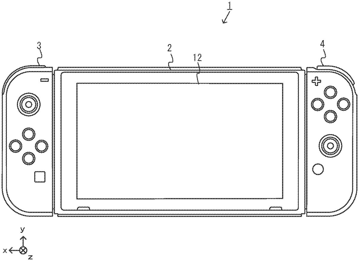
DETAILED DESCRIPTION OF NON-LIMITING EXAMPLE EMBODIMENTS A game system according to the present non-limiting example will now be described. A non-limiting example of a game system1according to the present non-limiting example includes a main body apparatus (information processing apparatus serving as the main body of a game apparatus in the present non-limiting example)2, a left controller3, and a right controller4. The left controller3and the right controller4are attachable to and detachable from the main body apparatus2. That is, the user can attach the left controller3and the right controller4to the main body apparatus2, and use them as a unified apparatus. The user can also use the main body apparatus2and the left controller3and the right controller4separately from each other (seeFIG.2). In the description that follows, a hardware configuration of the game system1of the present non-limiting example is described, and thereafter, the control of the game system1of the present non-limiting example is described. FIG.1is a diagram illustrating a non-limiting example of the state where the left controller3and the right controller4are attached to the main body apparatus2. As illustrated inFIG.1, each of the left controller3and the right controller4is attached to and unified with the main body apparatus2. The main body apparatus2is an apparatus for performing various processes (e.g., game processing) in the game system1. The main body apparatus2includes a display12. Each of the left controller3and the right controller4is an apparatus including operation sections with which a user provides inputs. FIG.2is a diagram illustrating a non-limiting example of the state where each of the left controller3and the right controller4is detached from the main body apparatus2. As illustrated inFIGS.1and2, the left controller3and the right controller4are attachable to and detachable from the main body apparatus2. It should be noted that hereinafter, the left controller3and the right controller4will occasionally be referred to collectively as a “controller.” FIG.3illustrates six orthogonal ...
DETAILED DESCRIPTION OF NON-LIMITING EXAMPLE EMBODIMENTS
A game system according to the present non-limiting example will now be described. A non-limiting example of a game system1according to the present non-limiting example includes a main body apparatus (information processing apparatus serving as the main body of a game apparatus in the present non-limiting example)2, a left controller3, and a right controller4. The left controller3and the right controller4are attachable to and detachable from the main body apparatus2. That is, the user can attach the left controller3and the right controller4to the main body apparatus2, and use them as a unified apparatus. The user can also use the main body apparatus2and the left controller3and the right controller4separately from each other (seeFIG.2). In the description that follows, a hardware configuration of the game system1of the present non-limiting example is described, and thereafter, the control of the game system1of the present non-limiting example is described.
FIG.1is a diagram illustrating a non-limiting example of the state where the left controller3and the right controller4are attached to the main body apparatus2. As illustrated inFIG.1, each of the left controller3and the right controller4is attached to and unified with the main body apparatus2. The main body apparatus2is an apparatus for performing various processes (e.g., game processing) in the game system1. The main body apparatus2includes a display12. Each of the left controller3and the right controller4is an apparatus including operation sections with which a user provides inputs.
FIG.2is a diagram illustrating a non-limiting example of the state where each of the left controller3and the right controller4is detached from the main body apparatus2. As illustrated inFIGS.1and2, the left controller3and the right controller4are attachable to and detachable from the main body apparatus2. It should be noted that hereinafter, the left controller3and the right controller4will occasionally be referred to collectively as a “controller.”
FIG.3illustrates six orthogonal views of a non-limiting example of the main body apparatus2. As illustrated inFIG.3, the main body apparatus2includes an approximately plate-shaped housing11. In the present non-limiting example, a main surface (in other words, a surface on a front side, i.e., a surface on which the display12is provided) of the housing11has a generally rectangular shape.
It should be noted that the shape and the size of the housing11are optional. As a non-limiting example, the housing11may be of a portable size. Further, the main body apparatus2alone or the unified apparatus obtained by attaching the left controller3and the right controller4to the main body apparatus2may function as a mobile apparatus. The main body apparatus2or the unified apparatus may function as a handheld apparatus or a portable apparatus.
As illustrated inFIG.3, the main body apparatus2includes the display12, which is provided on the main surface of the housing11. The display12displays an image generated by the main body apparatus2. In the present non-limiting example, the display12is a liquid crystal display device (LCD). The display12, however, may be a display device of any suitable type.
In addition, the main body apparatus2includes a touch panel13on the screen of the display12. In the present non-limiting example, the touch panel13allows multi-touch input (e.g., a capacitive touch panel). It should be noted that the touch panel13may be of any suitable type, e.g., it allows single-touch input (e.g., a resistive touch panel).
The main body apparatus2includes a speaker (i.e., a speaker88illustrated inFIG.6) inside the housing11. As illustrated inFIG.3, speaker holes11aand11bare formed in the main surface of the housing11. The speaker88outputs sounds through the speaker holes11aand11b.
The main body apparatus2also includes a left-side terminal17that enables wired communication between the main body apparatus2and the left controller3, and a right-side terminal21that enables wired communication between the main body apparatus2and the right controller4.
As illustrated inFIG.3, the main body apparatus2includes a slot23. The slot23is provided on an upper side surface of the housing11. The slot23is so shaped as to allow a predetermined type of storage medium to be attached to the slot23. The predetermined type of storage medium is, for example, a dedicated storage medium (e.g., a dedicated memory card) for the game system1and an information processing apparatus of the same type as the game system1. The predetermined type of storage medium is used to store, for example, data (e.g., saved data of an application or the like) used by the main body apparatus2and/or a program (e.g., a program for an application or the like) executed by the main body apparatus2. Further, the main body apparatus2includes a power button28.
The main body apparatus2includes a lower-side terminal27. The lower-side terminal27allows the main body apparatus2to communicate with a cradle. In the present non-limiting example, the lower-side terminal27is a USB connector (more specifically, a female connector). When the unified apparatus or the main body apparatus2alone is placed on the cradle, the game system1can display, on a stationary monitor, an image that is generated and output by the main body apparatus2. Also, in the present non-limiting example, the cradle has the function of charging the unified apparatus or the main body apparatus2alone, being placed thereon. The cradle also functions as a hub device (specifically, a USB hub).
FIG.4illustrates six orthogonal views of a non-limiting example of the left controller3. As illustrated inFIG.4, the left controller3includes a housing31. In the present non-limiting example, the housing31has a vertically long shape, e.g., is shaped to be long in an up-down direction (i.e., a y-axis direction illustrated inFIGS.1and4). In the state where the left controller3is detached from the main body apparatus2, the left controller3can also be held in the orientation in which the left controller3is vertically long. The housing31has such a shape and a size that when held in the orientation in which the housing31is vertically long, the housing31can be held with one hand, particularly the left hand. Further, the left controller3can also be held in the orientation in which the left controller3is horizontally long. When held in the orientation in which the left controller3is horizontally long, the left controller3may be held with both hands.
The left controller3includes an analog stick32. As illustrated inFIG.4, the analog stick32is provided on a main surface of the housing31. The analog stick32can be used as a direction input section with which a direction can be input. The user tilts the analog stick32and thereby can input a direction corresponding to the direction of the tilt (and input a magnitude corresponding to the angle of the tilt). It should be noted that the left controller3may include a directional pad, a slide stick that allows a slide input, or the like as the direction input section, instead of the analog stick. Further, in the present non-limiting example, it is possible to provide an input by pressing the analog stick32.
The left controller3includes various operation buttons. The left controller3includes four operation buttons33to36(specifically, a right direction button33, a down direction button34, an up direction button35, and a left direction button36) on the main surface of the housing31. Further, the left controller3includes a record button37and a “−” (minus) button47. The left controller3includes a first L-button38and a ZL-button39in an upper left portion of a side surface of the housing31. Further, the left controller3includes a second L-button43and a second R-button44, on the side surface of the housing31on which the left controller3is attached to the main body apparatus2. These operation buttons are used to give instructions depending on various programs (e.g., an OS program and an application program) executed by the main body apparatus2.
The left controller3also includes a terminal42that enables wired communication between the left controller3and the main body apparatus2.
FIG.5illustrates six orthogonal views of a non-limiting example of the right controller4. As illustrated inFIG.5, the right controller4includes a housing51. In the present non-limiting example, the housing51has a vertically long shape, e.g., is shaped to be long in the up-down direction. In the state where the right controller4is detached from the main body apparatus2, the right controller4can also be held in the orientation in which the right controller4is vertically long. The housing51has such a shape and a size that when held in the orientation in which the housing51is vertically long, the housing51can be held with one hand, particularly the right hand. Further, the right controller4can also be held in the orientation in which the right controller4is horizontally long. When held in the orientation in which the right controller4is horizontally long, the right controller4may be held with both hands.
Similarly to the left controller3, the right controller4includes an analog stick52as a direction input section. In the present non-limiting example, the analog stick52has the same configuration as that of the analog stick32of the left controller3. Further, the right controller4may include a directional pad, a slide stick that allows a slide input, or the like, instead of the analog stick. Further, similarly to the left controller3, the right controller4includes four operation buttons53to56(specifically, an A-button53, a B-button54, an X-button55, and a Y-button56) on a main surface of the housing51. Further, the right controller4includes a “+” (plus) button57and a home button58. Further, the right controller4includes a first R-button60and a ZR-button61in an upper right portion of a side surface of the housing51. Further, similarly to the left controller3, the right controller4includes a second L-button65and a second R-button66.
Further, the right controller4includes a terminal64for allowing the right controller4to perform wired communication with the main body apparatus2.
FIG.6is a block diagram illustrating a non-limiting example of an internal configuration of the main body apparatus2. The main body apparatus2includes components81to91,97, and98illustrated inFIG.6in addition to the components illustrated inFIG.3. Some of the components81to91,97, and98may be implemented as electronic parts on an electronic circuit board, which is contained in the housing11.
The main body apparatus2includes a processor81. The processor81is an information processor for executing various types of information processing to be executed by the main body apparatus2. For example, the CPU81may include only a central processing unit (CPU), or may be a system-on-a-chip (SoC) having a plurality of functions such as a CPU function and a graphics processing unit (GPU) function. The processor81executes an information processing program (e.g., a game program) stored in a storage section (specifically, an internal storage medium such as a flash memory84, an external storage medium that is attached to the slot23, or the like), thereby executing the various types of information processing.
The main body apparatus2includes a flash memory84and a dynamic random access memory (DRAM)85as examples of internal storage media built in itself. The flash memory84and the DRAM85are connected to the CPU81. The flash memory84is mainly used to store various data (or programs) to be saved in the main body apparatus2. The DRAM85is used to temporarily store various data used in information processing.
The main body apparatus2includes a slot interface (hereinafter abbreviated to “I/F”)91. The slot I/F91is connected to the processor81. The slot I/F91is connected to the slot23, and reads and writes data from and to a predetermined type of storage medium (e.g., a dedicated memory card) attached to the slot23, in accordance with commands from the processor81.
The processor81reads and writes, as appropriate, data from and to the flash memory84, the DRAM85, and each of the above storage media, thereby executing the above information processing.
The main body apparatus2includes a network communication section82. The network communication section82is connected to the processor81. The network communication section82communicates (specifically, through wireless communication) with an external apparatus via a network. In the present non-limiting example, as a first communication form, the network communication section82connects to a wireless LAN and communicates with an external apparatus, using a method compliant with the Wi-Fi standard. Further, as a second communication form, the network communication section82wirelessly communicates with another main body apparatus2of the same type, using a predetermined communication method (e.g., communication based on a particular protocol or infrared light communication). It should be noted that the wireless communication in the above second communication form achieves the function of allowing so-called “local communication,” in which the main body apparatus2can wirelessly communicate with another main body apparatus2located in a closed local network area, and the plurality of main body apparatuses2directly communicate with each other to exchange data.
The main body apparatus2includes a controller communication section83. The controller communication section83is connected to the processor81. The controller communication section83wirelessly communicates with the left controller3and/or the right controller4. The main body apparatus2may communicate with the left and right controllers3and4using any suitable communication method. In the present non-limiting example, the controller communication section83performs communication with the left and right controllers3and4in accordance with the Bluetooth (registered trademark) standard.
The processor81is connected to the left-side terminal17, the right-side terminal21, and the lower-side terminal27. When performing wired communication with the left controller3, the processor81transmits data to the left controller3via the left-side terminal17and also receives operation data from the left controller3via the left-side terminal17. Further, when performing wired communication with the right controller4, the processor81transmits data to the right controller4via the right-side terminal21and also receives operation data from the right controller4via the right-side terminal21. Further, when communicating with the cradle, the processor81transmits data to the cradle via the lower-side terminal27. As described above, in the present non-limiting example, the main body apparatus2can perform both wired communication and wireless communication with each of the left and right controllers3and4. Further, when the unified apparatus obtained by attaching the left and right controllers3and4to the main body apparatus2or the main body apparatus2alone is attached to the cradle, the main body apparatus2can output data (e.g., image data or sound data) to a stationary monitor or the like via the cradle.
Here, the main body apparatus2can communicate with a plurality of left controllers3simultaneously (or in parallel). Further, the main body apparatus2can communicate with a plurality of right controllers4simultaneously (or in parallel). Thus, a plurality of users can simultaneously provide inputs to the main body apparatus2, each using a set of left and right controllers3and4. As a non-limiting example, a first user can provide an input to the main body apparatus2using a first set of left and right controllers3and4, and at the same time, a second user can provide an input to the main body apparatus2using a second set of left and right controllers3and4.
Further, the display12is connected to the processor81. The processor81displays, on the display12, a generated image (e.g., an image generated by executing the above information processing) and/or an externally obtained image.
The main body apparatus2includes a codec circuit87and speakers (specifically, a left speaker and a right speaker)88. The codec circuit87is connected to the speakers88and an audio input/output terminal25and also connected to the processor81. The codec circuit87is for controlling the input and output of audio data to and from the speakers88and the sound input/output terminal25.
Further, the main body apparatus2includes an acceleration sensor89. In the present non-limiting example, the acceleration sensor89detects the magnitudes of accelerations along predetermined three axial (e.g., the x-, y-, and z-axes shown inFIG.1) directions. It should be noted that the acceleration sensor89may detect an acceleration along one axial direction or accelerations along two axial directions.
Further, the main body apparatus2includes an angular velocity sensor90. In the present non-limiting example, the angular velocity sensor90detects angular velocities about predetermined three axes (e.g., the x-, y-, and z-axes shown inFIG.1). It should be noted that the angular velocity sensor90may detect an angular velocity about one axis or angular velocities about two axes.
The acceleration sensor89and the angular velocity sensor90are connected to the processor81. The detection results of the acceleration sensor89and the angular velocity sensor90are output to the processor81. Based on the detection results of the acceleration sensor89and the angular velocity sensor90, the processor81can calculate information about a motion and/or orientation of the main body apparatus2.
The main body apparatus2includes a power control section97and a battery98. The power control section97is connected to the battery98and the processor81. Further, although not illustrated, the power control section97is connected to components of the main body apparatus2(specifically, components that receive power supplied from the battery98, the left-side terminal17, and the right-side terminal21). Based on a command from the processor81, the power control section97controls the supply of power from the battery98to each of the above components.
Further, the battery98is connected to the lower-side terminal27. When an external charging device (e.g., the cradle) is connected to the lower-side terminal27, and power is supplied to the main body apparatus2via the lower-side terminal27, the battery98is charged with the supplied power.
FIG.7is a block diagram illustrating non-limiting examples of the internal configurations of the main body apparatus2, the left controller3, and the right controller4. It should be noted that the details of the internal configuration of the main body apparatus2are illustrated inFIG.6and therefore are omitted inFIG.7.
The left controller3includes a communication control section101, which communicates with the main body apparatus2. As illustrated inFIG.7, the communication control section101is connected to components including the terminal42. In the present non-limiting example, the communication control section101can communicate with the main body apparatus2through both wired communication via the terminal42and wireless communication without via the terminal42. The communication control section101controls the method for communication performed by the left controller3with the main body apparatus2. That is, when the left controller3is attached to the main body apparatus2, the communication control section101communicates with the main body apparatus2via the terminal42. Further, when the left controller3is detached from the main body apparatus2, the communication control section101wirelessly communicates with the main body apparatus2(specifically, the controller communication section83). The wireless communication between the communication control section101and the controller communication section83is performed in accordance with the Bluetooth (registered trademark) standard, for example.
Further, the left controller3includes a memory102such as a flash memory. The communication control section101includes, for example, a microcomputer (or a microprocessor) and executes firmware stored in the memory102, thereby performing various processes.
The left controller3includes buttons103(specifically, the buttons33to39,43,44, and47). Further, the left controller3includes the analog stick (“stick” inFIG.7)32. Each of the buttons103and the analog stick32outputs information regarding an operation performed on itself to the communication control section101repeatedly at appropriate timing.
The left controller3includes inertial sensors. Specifically, the left controller3includes an acceleration sensor104. Further, the left controller3includes an angular velocity sensor105. In the present non-limiting example, the acceleration sensor104detects the magnitudes of accelerations along predetermined three axial (e.g., the x-, y-, and z-axes shown inFIG.4) directions. It should be noted that the acceleration sensor104may detect an acceleration along one axial direction or accelerations along two axial directions. In the present non-limiting example, an angular velocity sensor105detects angular velocities about predetermined three axes (e.g., the x-, y-, and z-axes shown inFIG.4). It should be noted that the angular velocity sensor105may detect an angular velocity about one axis or angular velocities about two axes. Each of the acceleration sensor104and the angular velocity sensor105is connected to the communication control section101. Then, the detection results of the acceleration sensor104and the angular velocity sensor105are output to the communication control section101repeatedly at appropriate timing.
The communication control section101acquires information regarding an input (specifically, information regarding an operation or the detection result of the sensor) from each of input sections (specifically, the buttons103and the analog stick32). The communication control section101transmits operation data including the acquired information (or information obtained by performing predetermined processing on the acquired information) to the main body apparatus2. It should be noted that the operation data is transmitted repeatedly, once every predetermined time. It should be noted that the interval at which the information regarding an input is transmitted from each of the input sections to the main body apparatus2may or may not be the same.
The above operation data is transmitted to the main body apparatus2, whereby the main body apparatus2can obtain inputs provided to the left controller3. That is, the main body apparatus2can determine operations on the buttons103and the analog stick32based on the operation data. Further, the main body apparatus2can calculate information regarding the motion and/or the orientation of the left controller3based on the operation data (specifically, the detection results of the acceleration sensor104and the angular velocity sensor105).
The left controller3includes a power supply section108. In the present non-limiting example, the power supply section108includes a battery and a power control circuit. Although not illustrated inFIG.7, the power control circuit is connected to the battery and also connected to components of the left controller3(specifically, components that receive power supplied from the battery).
As illustrated inFIG.7, the right controller4includes a communication control section111, which communicates with the main body apparatus2. Further, the right controller4includes a memory112, which is connected to the communication control section111. The communication control section111is connected to components including the terminal64. The communication control section111and the memory112have functions similar to those of the communication control section101and the memory102, respectively, of the left controller3. Thus, a communication control section111can communicate with the main body apparatus2through both wired communication via the terminal64and wireless communication without via the terminal64(specifically, communication compliant with the Bluetooth (registered trademark) standard). The communication control section111controls the method for communication performed by the right controller4with the main body apparatus2.
The right controller4includes input sections similar to the input sections of the left controller3. Specifically, the right controller4includes buttons113, the analog stick52, and inertial sensors (an acceleration sensor114and an angular velocity sensor115). These input sections have functions similar to those of the input sections of the left controller3and operate similarly to the input sections of the left controller3.
The right controller4includes a power supply section118. The power supply section118has a function similar to that of the power supply section108of the left controller3and operates similarly to the power supply section108.
As described above, in the game system1of the present non-limiting example, the left controller3and the right controller4are removable from the main body apparatus2. In addition, when the unified apparatus obtained by attaching the left controller3and the right controller4to the main body apparatus2or the main body apparatus2alone is attached to the cradle, an image (and sound) can be output on an external display device, such as a stationary monitor or the like. The game system1will be described below according to a non-limiting embodiment in which an image is displayed on the display12. It should be noted that in the case where the game system1is used in an embodiment in which an image is displayed on the display12, the game system1may be used with the left controller3and the right controller4attached to the main body apparatus2(e.g., the main body apparatus2, the left controller3, and the right controller4are integrated in a single housing).
A game is played using a virtual space displayed on the display12, according to operations performed on the operation buttons and sticks of the left controller3and/or the right controller4, or touch operations performed on the touch panel13of the main body apparatus2, in the game system1. In the present non-limiting example, as a non-limiting example, a game in which a player character PC and a field character FC, which perform an action on a field in the virtual space, and characters such as a fighting character BC that fights against the field character FC on the field, are employed, can be played according to the user's operation performed using the operation buttons, the sticks, and the touch panel13.
An overview of a game process executed in the game system1will be given with reference toFIGS.8to20. It should be noted thatFIG.8is a diagram illustrating a non-limiting example of a game image in a first stage of catching of a field character FC.FIG.9is a diagram illustrating a non-limiting example of a game image in a second stage of catching of a field character FC.FIG.10is a diagram illustrating a non-limiting example of a game image in a third stage of catching of a field character FC.FIG.11is a diagram illustrating a non-limiting example of a game image in a first stage of a fight between a field character FC and a fighting character BC.FIG.12is a diagram illustrating a non-limiting example of a game image in a second stage of a fight between a field character FC and a fighting character BC.FIG.13is a diagram illustrating a non-limiting example of a game image in a third stage of a fight between a field character FC and a fighting character BC.FIG.14is a diagram illustrating a non-limiting example of a game image in a fourth stage of a fight between a field character FC and a fighting character BC.FIG.15is a diagram illustrating a non-limiting example of a game image in a first stage of collection of a collection object OBJ by a fighting character BC.FIG.16is a diagram illustrating a non-limiting example of a game image in a second stage of collection of a collection object OBJ by a fighting character BC.FIG.17is a diagram illustrating a non-limiting example of a pictorial representation of a field character FC.FIG.18is a diagram illustrating a non-limiting example of a game image of an attack on a boss character MC.FIG.19is a diagram illustrating a non-limiting example of a game image in a first stage of a fight between a boss character MC and a fighting character BC.FIG.20is a diagram illustrating a non-limiting example of a game image in a second stage of a fight between a boss character MC and a fighting character BC.
First Non-Limiting Embodiment
A game process according to a first non-limiting embodiment will be described. In the first non-limiting embodiment, a player character PC is caused to perform different actions in different modes, i.e., switch between a first and a second mode. In the first mode, the player character PC is caused to perform an action of launching, at a field character FC as a target on a field, an item that affects a field character FC, according to an operation input for causing the player character PC to perform a launching action in the direction indicated by an aiming point M. In the second mode, the player character PC is caused to perform an action of launching, at a field character FC on a field, a fighting character BC that fights against a field character FC, according to an operation input for causing the player character PC to perform a launching action in the direction indicated by an aiming point M.
InFIG.8, a game image indicating that the player character PC is disposed in a virtual space is displayed on the display12of the game system1. The player character PC performs an action in the virtual space according to the user's operation. In the game image displayed on the display12, a field character FC disposed in the virtual space is displayed. A plurality of field characters FC are disposed on the field in the virtual space, and are caused to perform an action in the virtual space by automatic control performed by the processor81based on a predetermined algorithm or the like. A user who operates the player character PC can cause the player character PC to perform an action to catch a field character FC, and set the field character FC in the user's possession.
InFIG.8, the player character PC is holding an empty ball item B, and is about to throw the held ball item B in the virtual space. Here, the empty ball item B serves as a catching item that can be caused to hit a field character FC on the field and thereby catch the field character FC. For example, when an empty ball item B thrown by the player character PC hits a field character, it is determined whether or not the field character is successfully caught (successful-catch determination). If the result of the successful-catch determination is positive, the field character FC hit by the ball item B is successfully caught and set in the user's possession.
For example, the user can cause the player character PC to perform an action of getting into a throwing position for throwing a chosen item (e.g., an action of getting into the position illustrated inFIG.8), by performing a predetermined operation input (e.g., pressing down the operation button (ZR button)61). In addition, a direction in which the player character PC throws a chosen item is indicated by an aiming point M. The location of the aiming point M is moved according to a predetermined operation input (e.g., the direction of inclination of the analog stick32or52, the orientation of the body of the left controller3or the right controller4, or the motion or pointed location of the body of the left controller3or the right controller4). Thereafter, when the user ends the operation input for causing the player character PC to perform the action of getting into a throwing position (e.g., the user releases the operation button (ZR button)61), the player character PC is caused to perform an action of throwing the chosen item in the direction indicated by the aiming point M.
For example, the user can change categories of items to be thrown by the player character PC, by performing a predetermined operation input (e.g., pressing down the operation button (X button)55). In the first non-limiting embodiment, there are at least the first mode in which a first category including a plurality of items that affect a field character FC is chosen, and the second mode in which a second category including a plurality of fighting characters BC that fight against a field character FC on the field is chosen. The user can change the categories (modes) by pressing down the operation button55. The user can also choose an item to be thrown by the player character PC from the chosen category, by pressing down the operation button (L button)38or the operation button (R button)60. In the non-limiting example ofFIG.8, projectile information Im1is displayed, indicating that the first category (first mode) has been chosen, and an empty ball item B has been chosen from the first category by the user. For example, the first category may include a plurality of ball items having different functions or appearances, or items that are other than ball items and that when thrown, support the user in throwing a ball item and catching a field character by, for example, setting a limitation on a movement of the field character.
When an item chosen from the first category is a projectile, a first aiming point M1(e.g., an aiming point in a normal display form) is displayed. When an empty ball item B that can catch a field character FC is chosen as a projectile from the first category, the location of the first aiming point M1can be moved by the above operation of moving the aiming point M, or alternatively, the first aiming point M1can be set (locked on) to a location where the first aiming point M1is aligned with a field character FC by the user performing a predetermined operation input (e.g., pressing down the operation button (ZL button)39). When the first aiming point M1is locked on to the location of a field character FC, a thrown item is more likely to hit the field character FC.
When the first aiming point M1is locked on to a field character FC, catch information Ig indicating how likely the field character FC is to be caught by hitting the field character FC with an empty ball item B is displayed in the vicinity of the first aiming point M1. For example, an indicator indicating how likely the result of the successful-catch determination is to be positive when an empty ball item B thrown by the player character PC hits a field character FC, is displayed as the catch information Ig. The catch information Ig may be an indicator indicating one of a plurality levels indicating how likely the result of the successful-catch determination is to be positive, or an indicator indicating a numerical value indicating the probability or degree of the positive result of the determination. The catch information Ig may be an indicator representing how likely the result of the successful-catch determination is to be positive, by design or text, a size or motion, a color or lightness, or the like. The catch information Ig may not be displayed on the display12, and may be represented by sounds, vibrations applied to the controller3and/or4, or the like indicating how likely the result of the successful-catch determination is to be positive.
FIGS.9and10illustrate game images that are displayed on the display12, showing that an empty ball item B thrown by the player character PC hits a field character FC, so that the field character FC is successfully caught. For example, the user ends an operation input of causing the player character PC to get into a throwing position (e.g., the user releases the operation button (ZR button)61), and thereby, can allow the player character PC to perform an action of throwing a chosen item in the direction indicated by the first aiming point M1. When the empty ball item B thrown by the player character PC hits a field character FC, a scene image showing that the field character FC is hit (and/or caught) is displayed as illustrated inFIG.9. When the field character FC is successfully caught, a scene image showing the field character FC is put into the empty ball item B, which means that the field character FC is caught, is displayed as illustrated inFIG.10. Thereafter, the field character FC successfully caught is set in the user's possession. It should be noted that the field character FC successfully caught may be allowed to be used as a fighting character BC in the subsequent process by the user.
When the empty ball item B thrown by the player character PC does not hit a field character FC, or the player character PC fails to catch a field character FC, a scene image showing such a situation is displayed on the display12. Here, when the player character PC fails to catch a field character FC, there may be a disadvantage such as the escape of the field character FC, or the outbreak of a fight due to an attack by the field character FC.
Although it is assumed above that a condition for catching a field character FC is that an empty ball item B thrown by the player character PC hits the field character FC, the field character FC may be caught if the empty ball item B reaches a predetermined range including the location of the field character FC irrespective of whether the empty ball item B hits the field character FC. In that case, how likely it is to catch a field character FC may be changed, depending on whether the field character FC is hit.
In addition, how likely it is to catch a field character FC may be changed according to a state (emotions, endurance, remaining physical strength, size, movement, or the like) of the field character FC to be caught, or the type of an item (e.g., the type of an empty ball item B) thrown by the player character PC. Even when how likely it is to catch a field character FC is changed, the user can know the change from the catch information Ig, which is displayed in the vicinity of the first aiming point M1.
Although in the first non-limiting embodiment, an empty ball item B is used as a non-limiting example of an item that is chosen from the first category (first mode) including a plurality of items that affect a field character FC, the first category may include other types of items. For example, the first category may include an item that slows the movement of a hit field character FC, an item that deprives physical strength of a hit field character FC, an item that changes emotions of a hit field character FC, and an item that attracts a field character FC. By using a combination of these items to hit and attract a field character FC (an item is placed at a location to which a field character FC should be attracted) and the like, the effect of making it more likely to catch a field character FC by throwing a catching item (e.g., an empty ball item B) can be expected.
InFIG.11, the player character PC is holding a ball item Bs containing a fighting character BC, and is about to throw the held ball item Bs in the virtual space in the second mode. Here, when the ball item Bs containing a fighting character BC is thrown on the field, the fighting character BC appears in the virtual space. For example, when the player character PC throws the ball item Bs at near a field character FC, the fighting character BC appears from the ball item Bs and starts fighting against the field character FC. It should be noted that a fight is directly started on the field without changing places.
For example, the user can cause the player character PC to perform an action of getting into a throwing position for throwing a chosen fighting character BC (ball item Bs) (e.g., an action of getting into the position illustrated inFIGS.11andFIG.12), by performing a predetermined operation input (e.g., pressing down the operation button (ZR button)61). In addition, a direction in which the player character PC throws the chosen fighting character BC (ball item Bs) is indicated by the aiming point M. The location of the aiming point M is moved according to a predetermined operation input (e.g., the direction of inclination of the analog stick32or52, the orientation of the body of the left controller3or the right controller4, or the motion or pointed location of the body of the left controller3or the right controller4). Thereafter, when the user ends the operation input for causing the player character PC to perform the action of getting into a throwing position (e.g., the user releases the operation button (ZR button)61), the player character PC is caused to perform an action of throwing the chosen fighting character BC (ball item Bs) in the direction indicated by the aiming point M.
As described above, the user can change the category to the second category (second mode) including a plurality of fighting characters BC by performing a predetermined operation input (e.g., pressing down the operation button (X button)55). Thereafter, the user can choose a fighting character BC that the player character PC is to throw, from the chosen second category, by performing a predetermined operation input (e.g., pressing down the operation button (L button)38or the operation button (R button)60). For example, in the non-limiting examples ofFIGS.11and12, projectile information Im2is displayed, indicating that the second category (second mode) has been chosen, and the user has chosen a predetermined fighting character BC from the second category.
When a fighting character BC (a ball item Bs containing a fighting character BC) is chosen as a projectile from the second category, a second aiming point M2is displayed. The second aiming point M2is displayed in a form different that of the first aiming point M1. As a non-limiting example, the second aiming point M2does not have the normal display form, and is displayed as a colored mark imitating a ball item Bs containing a fighting character BC. By thus displaying the second aiming point M2in a display form different from that of the first aiming point M1, a projectile that the player character PC is trying to throw can be easily recognized while seeing the aiming point.
As illustrated inFIG.12, when the second aiming point M2is disposed, overlaying a range in which a field character FC and a fighting character BC can fight against each other, the second aiming point M2is changed to a third aiming point M3. The third aiming point M3is displayed in a display form that is different from those of the first aiming point M1and the second aiming point M2. As a non-limiting example, the third aiming point M3is displayed as a mark to which a design indicating a fight is added at a center of the second aiming point M2. By thus displaying the third aiming point M3in a display form different from those of the first aiming point M1and the second aiming point M2, the user is allowed to easily recognize that the player character PC can fight against a field character FC by throwing a ball item Bs containing a fighting character BC, while seeing the aiming point.
InFIG.13, the display12displays a game image in which a fighting character BC appearing from a ball item Bs thrown by the player character PC is fighting against a field character FC. For example, the user can cause the player character PC to perform an action of throwing a ball item Bs containing a chosen fighting character BC in the direction indicated by the third aiming point M3by ending an operation input for causing the player character PC to get into a throwing position (e.g., releasing the operation button (ZR button)61). When the ball item Bs thrown by the player character PC reaches a range in which the fighting character BC can fight against the field character FC, the fighting character BC appears from that range. Thereafter, the fighting character BC starts fighting against the field character FC. Thus, in the first non-limiting embodiment, by causing the player character PC to perform the same action, i.e., an action of throwing a projectile in the direction indicated by the aiming point M, the field character FC can be subjected to various situations on the field, because the categories (modes) of a projectile can be changed.
While a fighting character BC is fighting against a field character FC, a gauge G1indicating a state of the field character FC is displayed at a location that is set, corresponding to a location of the field character FC. Here, the state of the field character FC indicated by the gauge G1indicates at least a parameter related to the remaining physical strength of the field character FC during a fight against the fighting character BC. When an attack on the field character FC by the fighting character BC is effective, the parameter gradually decreases according to the attack. When the remaining physical strength indicated by the gauge G1is zero, the fighting character BC wins the fight. As described below, the state of the field character FC indicated by the gauge G1also indicates how likely it is to catch the field character FC during the fight.
As illustrated inFIG.14, while a fighting character BC is fighting against a field character FC, the user can control actions of the player character PC and/or the fighting character BC by choosing commands. For example, while a fighting character BC is fighting against a field character FC, a plurality of command-indicating images C for allowing the user to choose a command are displayed. For example, inFIG.14, as a non-limiting example of the command-indicating images C, an attack command, an item command, an appear/disappear command, and an escape command are displayed. The user can choose any of the commands by performing an operation input using an input section provided on the left controller3or the right controller4, or the touch panel13of the main body apparatus2.
The user can control an action of a fighting character BC by performing an operation input for choosing the attack command. As a non-limiting example, when the attack command is chosen, the user is prompted to choose one of a plurality of kinds of attack. By performing an operation of choosing one from the plurality of kinds of attack, the user can cause a fighting character BC to perform an attack action corresponding to the chosen kind of attack.
The user can control an action of the player character PC by performing an operation input for choosing the item command. As a non-limiting example, when the item command is chosen, the user is prompted to choose one of a plurality of items including a catching item. By performing an operation of choosing an item to be used from the plurality of items, the user can cause the player character PC to perform an action of using the chosen item. As a non-limiting example, by performing an operation of choosing a catching item for catching a field character FC during the fight, the user can cause the player character PC to perform an action of catching a field character FC using the catching item.
A catching item used during a fight may be the same as or similar to the above ball item B. For example, when the command to use a catching item is chosen during the fight, a scene that the player character PC throws a catching item at a field character FC during the fight is displayed. As to whether or not the field character FC is successfully caught, successful-catch determination is performed as in the non-fight state. During the fight, the successful-catch determination is performed based on a state of the field character FC that is changed during the fight, i.e., the state of the field character FC indicated by the gauge G1. Specifically, when a state (e.g., the remaining physical strength) of the field character FC changed due to the fight is reduced to a predetermined state, the result of the successful-catch determination is more likely to be positive. It should be noted that the above threshold may be changed according to at least one of the type of the field character FC, the type of the chosen catching item, an ability value of the player character PC, an ability value of the fighting character BC, and the like. Even when the result of the successful-catch determination is positive during the fight, the field character FC is caught by the command using the catching item, and is set in the user's possession. As another non-limiting example, while a fighting character BC is fighting against a field character FC, the player character PC may be caused to perform an action of catching the field character FC using a catching item, by performing an operation input of causing the player character PC to perform an action of throwing the catching item at the aiming point M as in catching instead of the operation of choosing a command unlike the above fight.
The user can cause a fighting character BC to disappear during the fight or can cause another fighting character BC to appear during the fight, by performing an operation input of choosing the appear/disappear command. It should be noted that the existing fighting character BC may be replaced by another fighting character BC that newly appears, or in addition to the existing fighting character BC, another fighting character BC may newly appear. As a non-limiting example, when the appear/disappear command is chosen, the user is prompted to choose one of a plurality of characters that is to appear, and by operating an operation of choosing the one from the plurality of characters, the user can cause the player character PC to perform an action of causing the chosen character to appear as a fighting character BC.
The user can end a fight between a fighting character BC and a field character FC, and control an action of the player character PC such that the player character PC performs an action of escaping from the field character FC, by performing an operation input of choosing the escape command. At that time, the appearing fighting character BC may be collected by the player character PC to disappear from the field, or may be left as it is on the field.
Thus, in a fight between a fighting character BC and a field character FC, the field character FC can be caught by choosing the command to use a catching item as in the non-fight state. Therefore, the user can choose whether to catch a field character FC without fighting against the field character FC using a fighting character BC, or to catch a field character FC by performing the fight, resulting in a game having various strategic aspects.
Although in the first non-limiting embodiment, a fighting character BC is released in the virtual space by the player character PC throwing a ball item Bs containing the fighting character BC in the direction indicated by the aiming point M, a fighting character BC may be released in the virtual space by the player character PC directly throwing the fighting character BC.
The location and orientation of a virtual camera for generating a game image to be displayed on the display12may be set such that the virtual camera is located behind the player character PC, and the player character PC is included in the range of view of the virtual camera, or such that the first-person point of view of the player character PC is provided. In either case, the location and/or orientation of the virtual camera may be changeable according to the user's operation input. In that case, a field character FC may be out of the range of view during the fight or the gauge G1indicating a state of the field character FC may be out of the display range, depending on the location or orientation of the player character PC in the virtual space. If the location and/or orientation of the virtual camera are changeable according to the user's operation input even during a fight between a fighting character BC and a field character FC, then when a fight between a field character FC and a fighting character BC starts without the field character FC being displayed, the gauge G1indicating a state of the field character FC, i.e., an indicator affecting catching of the field character FC, can be displayed according to the user's operation. The player character PC may be allowed to freely move during a fight according to the user's operation input. Therefore, no matter what kind of situation a fight starts in, the camera can be subsequently appropriately changed by the user. Therefore, a fight can be caused to start freely irrespective of situations.
In addition, in the first non-limiting embodiment, a fighting character BC appearing from a ball item Bs can be caused to perform an action different from that during the fight on the field. For example, in the first non-limiting embodiment, when the player character PC throws a ball item Bs containing a fighting character BC on the field in the virtual space, the fighting character BC may be caused to merely appear on the field, or the fighting character BC may be caused to appear and perform a predetermined action on a virtual object OBJ disposed on the field.
For example, as illustrated inFIG.15, a collection object OBJ is disposed on the field in the virtual space. In the first non-limiting embodiment, the player character PC may collect the collection object OBJ by directly touching the collection object OBJ, and a fighting character BC may be caused to appear and collect the collection object OBJ.
InFIG.15, the player character PC is holding a ball item Bs containing a fighting character BC as in the state ofFIG.11, and is performing an action of getting into a throwing position for throwing the chosen fighting character BC (ball item Bs), according to a predetermined operation input (e.g., pressing down the operation button (ZR button)61). In the non-limiting example ofFIG.15, the projectile information Im2is displayed, indicating that the second category (second mode) has been chosen, and a predetermined fighting character BC has been chosen from the second category by the user.
As described above, when a fighting character BC (a ball item Bs containing the fighting character BC) chosen from the second category is a projectile, the second aiming point M2is displayed. When the second aiming point M2is disposed, overlaying the range in which an action of collecting a collection object OBJ is allowed, the second aiming point M2is changed to a fourth aiming point M4. The fourth aiming point M4is displayed in a display form different from those of the first aiming point M1, the second aiming point M2, and the third aiming point M3. As a non-limiting example, the fourth aiming point M4is displayed as a mark in which a design imitating a portion of the fighting character BC is added at a center of the second aiming point M2. Thus, by displaying the fourth aiming point M4in a display form different from those of the first aiming point M1, the second aiming point M2, and the third aiming point M3, it is more easily recognized that the field character FC can be caused to appear in a state different from the fight state by throwing the ball item Bs containing the fighting character BC, while seeing the aiming point.
InFIG.16, a game image that a fighting character BC appearing from a ball item Bs thrown by the player character PC is collecting a collection object OBJ is displayed on the display12. For example, the user stops performing an operation input for causing the player character PC to perform an action of getting into a throwing position (e.g., the user releases the operation button (ZR button)61), and thereby can cause the player character PC to perform an action of throwing a ball item Bs containing a chosen fighting character BC in the direction indicated by the fourth aiming point M4. When the ball item Bs thrown by the player character PC reaches a range in which the player character PC can collect a collection object OBJ, the fighting character BC appears from the range. Thereafter, the fighting character BC starts collecting the collection object OBJ.
In the first non-limiting embodiment, information about a field character FC to which the aiming point M is locked on can be displayed (pictorial representation). For example, when a predetermined operation input (e.g., pressing down the operation button (down button)34or the down button of the directional pad) is performed with the first aiming point M1locked on to the field character FC as illustrated inFIG.8, i.e., an operation of displaying a pictorial representation is performed while performing an operation of locking the first aiming point M1on to the field character FC, information about the field character FC is displayed as illustrated inFIG.17. Here, information about a field character FC includes mission information about a history of missions in a game including at least the number of field characters FC to which the aiming point M is locked on and which have been caught by the player character PC and the number of times of a fight against the field character FC. In a non-limiting example of a pictorial representation of field characters FC illustrated inFIG.17, for a field character A of a plurality of field characters FC to which the aiming point M is locked on, the history of each of features such as the number of catches (the number of times a field character A was caught), the number of heavy size catches (the number of times a relatively heavy field character A was caught), the number of times of a fight (the number of times of a fight against a field character A), the number of beaten field characters A (the number of field characters A that were beaten during a fight), and the number of types of observed field characters A (the number of types of field characters A that appeared in the virtual space and were displayed on the display12) is displayed as information about the field character FC. In the non-limiting example of the pictorial representation of field characters FC ofFIG.17, a mission to be accomplished and the progress of the mission are displayed for each feature. As a non-limiting example, as the mission information, for each feature of the pictorial representation, a value required for accomplishing a mission (the number of times required for accomplishing a mission) is displayed for each stage. For a mission that has already been accomplished, a mark (check mark in the non-limiting example ofFIG.17) indicating that the mission already has been accomplished is given to the value required for accomplishing the mission.
Thus, the history information of a mission to be accomplished for a field character FC on the field is displayed, and can be referenced for choosing whether to catch the field character FC or fight against the field character FC. It should be noted that information about a field character FC different from the field character A to which an aiming point is locked on may also be displayed. For example, in the non-limiting example ofFIG.17, a tag is provided at a right end of a display screen for each field character FC (e.g., field characters A to E), and information about the other field characters FC can be displayed by performing an operation of choosing the respective corresponding tags.
Second Non-Limiting Embodiment
A game process according to a second non-limiting embodiment will be described. In this non-limiting embodiment, a player character PC can fight against a boss character MC that is a non-limiting example of a field character disposed on a field in a virtual space. In the second non-limiting embodiment, a game process is performed on the boss character MC. Here, the boss character MC appears on the same field in the same virtual space on which a field character FC appears, and attacks the player character PC and moves toward the player character PC. Therefore, the user may operate the player character PC such that the player character PC escapes an attack from the boss character MC, or the player character PC hits the boss character MC with a boss attack item AI. In the second non-limiting embodiment, the player character PC is caused to perform different actions in different modes, i.e., switch between a first and a second mode. In the first mode, the player character PC is caused to perform an action of launching, at the boss character MC as a target on the field, an item that affects the boss character MC, according to an operation input for causing the player character PC to perform a launching action in the direction indicated by an aiming point M. In the second mode, the player character PC is caused to perform an action of launching, at the boss character MC on the field, a fighting character BC that fights against the boss character MC, according to an operation input for causing the player character PC to perform a launching action in the direction indicated by an aiming point M.
InFIG.18, a game image that the player character PC and the boss character MC are disposed in the virtual space is displayed on the display12. For example, the boss character MC appears in the virtual space in a special event (e.g., a boss fight event) during progression of a game, and is operated on the field in the virtual space by automatic control performed by the processor81based on a predetermined algorithm or the like as with a field character FC. The user who operates the player character PC can cause the player character PC or a fighting character BC to fight against the boss character MC. It should be noted that the boss character MC may be forbidden to be caught, unlike the above field character FC.
InFIG.18, the player character PC is holding a boss attack item AI, and is about to throw the held boss attack item AI in the virtual space. Here, the boss fight event can be progressed by hitting the boss character MC on the field with the boss attack item AI. For example, a boss state parameter that indicates a state of the boss character MC in the boss fight event is provided. The boss state parameter is reduced when the boss attack item AI hits the boss character MC. As a non-limiting example, when the boss attack item AI thrown by the player character PC hits the boss character MC, the attack is assessed based on the site of the hit, the state of the boss character MC, and the like, and a reduction amount based on the assessment of the attack is subtracted from the boss state parameter of the boss character MC. When the boss state parameter is reduced to reach a threshold (e.g., zero), the boss character MC is beaten, so that the boss fight event is cleared. In the non-limiting example of a game image ofFIG.18, a gauge G2indicating the remaining amount of the boss state parameter of the boss character MC is displayed at an upper portion of a display screen.
In the boss fight event, the user can also cause the player character PC to perform an action of getting into a throwing position for throwing a chosen boss attack item AI (e.g., an action of getting into the position illustrated inFIG.18) by performing a predetermined operation input (e.g., pressing down the operation button (ZR button)61). A direction in which the player character PC throws a chosen boss attack item AI is indicated by a first aiming point M1. The location of the first aiming point M1is moved according to a predetermined operation input (e.g., the direction of inclination of the analog stick32or52, the orientation of the body of the left controller3or the right controller4, or the motion or pointed location of the body of the left controller3or the right controller4). Thereafter, when the user ends the operation input for causing the player character PC to perform the action of getting into a throwing position (e.g., the user releases the operation button (ZR button)61), the player character PC is caused to perform an action of throwing the chosen boss attack item AI in the direction indicated by the first aiming point M1.
In the boss fight event, the user can also change categories of an item to be thrown by the player character PC, by performing a predetermined operation input (e.g., pressing down the operation button (X button)55). In the second non-limiting embodiment, there are at least the first mode in which a first category including a plurality of items that affect the boss character MC is chosen, and the second mode in which a second category including a plurality of fighting characters BC that fight against the boss character MC on the field is chosen. The user can change the categories (modes) by pressing down the operation button55. The user can also choose an item to be thrown by the player character PC from the chosen category, by pressing down the operation button (L button)38or the operation button (R button)60. For example, in the non-limiting example ofFIG.18, projectile information Im3is displayed, indicating that the first category (first mode) has been chosen, and a boss attack item AI has been chosen from the first category by the user. In the boss fight event, when a boss attack item AI is chosen as a projectile from the first category, the first aiming point M1(e.g., an aiming point in a normal display form) is also displayed.
As described above, when the user ends the operation input of causing the player character PC to perform an action of getting into a throwing position (e.g., the user releases the operation button (ZR button)61), the player character PC can be caused to perform an action of throwing a chosen boss attack item AI in the direction indicated by the first aiming point M1. When the boss attack item AI thrown by the player character PC hits the boss character MC, the boss state parameter of the boss character MC is reduced based on the above attack assessment. When the boss attack item AI thrown by the player character PC fails to hit the boss character MC, the boss state parameter of the boss character MC is maintained, or the boss state parameter is increased by a predetermined amount.
Although in the foregoing, a condition for reducing the boss state parameter of the boss character MC is that a boss attack item AI thrown by the player character PC hits the boss character MC, the boss state parameter of the boss character MC may be reduced if the boss attack item AI reaches a predetermined range including the location of the boss character MC irrespective of whether the boss attack item AI directly hits the boss character MC.
Although in the second non-limiting embodiment, a boss attack item AI is used as a non-limiting example of an item chosen from the first category (first mode) including a plurality of items that affect the boss character MC, the first category may include other types of items. For example, the first category may include an item that slows the movement of the boss character MC when the item hits the boss character, an item that changes emotions of the boss character MC when the item hits the boss character, and an item that attracts the boss character MC. By using a combination of these items to hit and attract the boss character MC (an item is placed at a location to which the boss character MC should be attracted) and the like, the effect of making it more likely for a boss attack item AI to hit the boss character MC can be expected.
In the second non-limiting embodiment, a fighting character BC may be caused to appear on the field and fight against the boss character MC. InFIG.19, the player character PC is holding a ball item Bs containing a fighting character BC, and is about to throw the held ball item Bs in the virtual space. Here, when the ball item Bs containing a fighting character BC is thrown on the field in the boss fight event, the fighting character BC appears in the virtual space. For example, when the player character PC throws the ball item Bs at near the boss character MC, the fighting character BC appears from the ball item Bs and starts fighting against the boss character MC. It should be noted that a fight is directly started on the field without changing places.
For example, in the boss fight event, the user can also cause the player character PC to perform an action of getting into a throwing position for throwing a chosen fighting character BC (ball item Bs) (e.g., an action of getting into the position illustrated inFIG.19), by performing a predetermined operation input (e.g., pressing down the operation button (ZR button)61). In addition, a direction in which the player character PC throws the chosen fighting character BC (ball item Bs) is indicated by a second aiming point M2. The location of the second aiming point M2is moved according to a predetermined operation input (e.g., the direction of inclination of the analog stick32or52, the orientation of the body of the left controller3or the right controller4, or the motion or pointed location of the body of the left controller3or the right controller4). As illustrated inFIG.19, in the boss fight event, when the second aiming point M2is disposed, overlaying a range in which the boss character MC and the fighting character BC can fight against each other, the second aiming point M2is changed to a third aiming point M3.
In the boss fight event, the user can also change the category to the second category (second mode) including a plurality of fighting characters BC by performing a predetermined operation input (e.g., pressing down the operation button (X button)55). Thereafter, the user can choose a fighting character BC that the player character PC is to throw, from the chosen second category, by performing a predetermined operation input (e.g., pressing down the operation button (L button)38or the operation button (R button)60). For example, in the non-limiting examples ofFIGS.19and20, projectile information Im2is displayed, indicating that the second category (second mode) has been chosen, and the user has chosen a predetermined fighting character BC from the second category.
InFIG.20, a game image that a fighting character BC appearing from a ball item Bs thrown by the player character PC is fighting against the boss character MC is displayed on the display12. For example, in the boss fight event, the user can also cause the player character PC to perform an action of throwing a ball item Bs containing a chosen fighting character BC in the direction indicated by the third aiming point M3by ending an operation input for causing the player character PC to get into a throwing position (e.g., releasing the operation button (ZR button)61). When the ball item Bs thrown by the player character PC reaches a range in which the fighting character BC can fight against the boss character MC, the fighting character BC appears from that range. Thereafter, the fighting character BC starts fighting against the boss character MC. Thus, in the second non-limiting embodiment, by causing the player character PC to perform the same action, i.e., an action of throwing a projectile in the direction indicated by the aiming point M, the boss character MC can be subjected to various situations on the field, because the categories (modes) of a projectile can be changed.
While a fighting character BC is fighting against the boss character MC, a gauge G3indicating a state of the boss character MC is displayed at a location that is set, corresponding to a location of the boss character MC. Here, the state of the boss character MC indicated by the gauge G3indicates at least a parameter related to the remaining physical strength of the boss character MC during a fight against the fighting character BC. When an attack on the boss character MC by the fighting character BC is effective, the parameter gradually decreases according to the attack. When the remaining physical strength of the boss character MC indicated by the gauge G3is zero, the fighting character BC wins the fight.
While a fighting character BC is fighting against the boss character MC, the user can control an action of the fighting character BC by choosing a command. As a non-limiting example, by performing an operation of choosing one from a plurality of attack commands, the user can cause a fighting character BC to perform an attack action corresponding to the chosen attack command.
When a fighting character BC wins a fight against the boss character MC, a condition for clearing the boss fight event is adjusted so as to be more easily satisfied. As a first non-limiting example, when a fighting character BC wins a fight against the boss character MC, a limitation is set on the movement in the virtual space of the boss character MC during at least a predetermined period of time. This allows the user to more easily hit the boss character MC with a boss attack item AI, and therefore, to more easily reduce the boss state parameter for clearing the boss fight event, so that the condition for clearing the boss fight event is more easily satisfied. As a second non-limiting example, when a fighting character BC wins a fight against the boss character MC, the amount of a reduction in the boss state parameter corresponding to hitting of the boss character MC with a boss attack item AI is relatively increased during at least a predetermined period of time. This allows the user to more easily reduce the boss state parameter, so that the condition for clearing the boss fight event is more easily satisfied. As a third non-limiting example, when a fighting character BC wins a fight against the boss character MC, the boss state parameter as of the end of the fight is reduced by a predetermined amount. This allows the user to more easily reduce the boss state parameter, so that the condition for clearing the boss fight event is more easily satisfied. It should be noted that in the second non-limiting embodiment, by combining at least two of the above non-limiting examples, the condition for clearing the boss fight event may be adjusted so as to be more easily satisfied.
It should be noted that a fight between a fighting character BC and the boss character MC in the boss fight event may be allowed to start only when the boss character MC is in a predetermined state. For example, the predetermined state may be a state that the boss character MC is in an unguarded moment, a state that the boss character MC is in a predetermined position, a state that the boss state parameter of the boss character MC has reached a predetermined value, a state that a predetermined period of time has passed since the start of the boss fight event, or the like. In addition, the fight may not be forbidden to start in a state that a fighting character BC does not appear even when the player character PC throws a ball item Bs, a state that the player character PC does not perform a throwing action even when the user performs an operation input for causing the player character PC to perform a throwing action, a state that a ball item Bs cannot be chosen as a projectile, or the like.
Thus, in the second non-limiting embodiment, in the boss fight event, in which the boss character MC appears, an operation of throwing an item that affects the boss character MC (boss attack item AI) in the direction indicated by an aiming point, and an operation of throwing a fighting character BC that fights against the boss character MC in the direction indicated by an aiming point, can be allowed, and therefore, the user can choose whether to attack the boss character MC using an item or attack the boss character MC using a fighting character BC, resulting in a game having various strategic aspects.
In the boss fight event, the location and orientation of a virtual camera for generating a game image to be displayed on the display12may be set such that the virtual camera is located behind the player character PC, and the player character PC is included in the range of view of the virtual camera, or such that the first-person point of view of the player character PC is provided. In either case, the location and/or orientation of the virtual camera may be changeable according to the user's operation input.
In the first and second non-limiting embodiments, the player character PC performs a throwing action in the direction indicated by an aiming point in different modes that can be changed, i.e., the first and second modes. A larger number of modes may be provided. For example, there may be a category including a plurality of items that affect a fighting character BC, a category including a plurality of items that affect a collection object OBJ, a category including a plurality of items that affect the player character PC, a category including a plurality of items that affect the virtual space, and the like. By allowing choice of these categories, three or more modes may be changed.
Next, a non-limiting example of a specific process executed in the game system1in the first and second non-limiting embodiments will be described with reference toFIGS.21to26.FIG.21is a diagram illustrating a non-limiting example of a data area set in the DRAM85of the main body apparatus2in the first and second non-limiting embodiments. It should be noted that in addition to the data illustrated inFIG.21, the DRAM85may also store data used in other processes, and those data will not be described in detail.
Various programs Pa that are executed in the game system1are stored in a program storage area of the DRAM85. In this non-limiting example, the programs Pa include an application program (e.g., a game program) for performing information processing based on data obtained from the left controller3and/or the right controller4, and the main body apparatus2. Note that the programs Pa may be previously stored in the flash memory84, may be obtained from a storage medium removably attached to the game system1(e.g., a predetermined type of storage medium attached to the slot23) and then stored in the DRAM85, or may be obtained from another apparatus via a network, such as the Internet, and then stored in the DRAM85. The processor81executes the programs Pa stored in the DRAM85.
Various kinds of data that are used in processes such as an information process that are executed in the game system1are stored in a data storage area of the DRAM85. In this non-limiting example, the DRAM85stores operation data Da, player character data Db, field character data Dc, boss character data Dd, fighting character data De, collection object data Df, obtained character data Dg, history data Dh, item data Di, aiming point data Dj, catch information data Dk, character fight flag data Dm, image data Dn, and the like.
The operation data Da is obtained, as appropriate, from each of the left controller3and/or the right controller4and the main body apparatus2. As described above, the operation data obtained from each of the left controller3and/or the right controller4and the main body apparatus2includes information about an input from each input section (specifically, each button, an analog stick, or a touch panel) (specifically, information about an operation). In this non-limiting example, operation data is obtained from each of the left controller3and/or the right controller4and the main body apparatus2. The obtained operation data is used to update the operation data Da as appropriate. Note that the operation data Da may be updated for each frame that is the cycle of a process executed in the game system1, or may be updated each time operation data is obtained.
The player character data Db indicates the place and position of the player character PC disposed in the virtual space, the movement and state in the virtual space of the player character PC, and the like.
The field character data Dc indicates the type, place, position, movement, and state of each field character FC disposed in the virtual space, and the like. The boss character data Dd indicates the type, place, position, movement, and state of the boss character MC disposed in the virtual space, and the like.
The fighting character data De indicates the type, place, position, movement, and state of a fighting character BC appearing in the virtual space, and the like.
The collection object data Df indicates the type, place, position, and state of each collection object OBJ disposed in the virtual space, and the like.
The obtained character data Dg indicates the types and number of field characters FC (fighting characters) obtained by the user by catching or the like, and the like.
The history data Dh indicates mission information about the history of missions in a game.
The item data Di indicates the types and number of items possessed by the player character PC, and the like.
The aiming point data Dj indicates the types and locations of aiming points that are a target for a projectile that is thrown by the player character PC.
The catch information data Dk relates to catch information indicating how likely the result of successful-catch determination is to be positive for a field character FC to which an aiming point is locked on.
The character fight flag data Dm indicates a character fight flag that is set on when a fight using a fighting character BC is allowed in the boss fight event.
The image data Dn is used to display, on a display screen (e.g., the display12of the main body apparatus2), images (e.g., an image of the player character PC, an image of a field character FC, an image of the boss character MC, an image of a fighting character BC, an image of each item, an image of a collection object OBJ or other objects, an image of an aiming point, an image of the virtual space, and a background image).
Next, a specific non-limiting example of a game process in the first and second non-limiting embodiments will be described with reference toFIGS.22to26.FIG.22is a flowchart illustrating a non-limiting example of a game process executed in the game system1.FIG.23is a subroutine illustrating a specific non-limiting example of an item use process executed in step S125ofFIG.22.FIG.24is a subroutine illustrating a specific non-limiting example of a first character use process executed in step S127ofFIG.22.FIG.25is a subroutine illustrating a specific non-limiting example of a boss item use process executed in step S130ofFIG.22.FIG.26is a subroutine illustrating a specific non-limiting example of a second character use process executed in step S132ofFIG.22. In the present non-limiting example, the processes ofFIGS.22to26are executed by the processor81executing a predetermined application program (game program) included the programs Pa. The processes ofFIGS.22to26are started with any appropriate timing.
It should be noted that steps in the flowcharts ofFIGS.22to26, which are merely illustrative, may be executed in a different order, or another step may be executed in addition to (or instead of) each step, if a similar effect is obtained. In this non-limiting example, it is assumed that the processor81executes each step of the flowchart. Alternatively, a portion of the steps of the flowchart may be executed by a processor or dedicated circuit other than the processor81. In addition, a portion of the steps executed by the main body apparatus2may be executed by another information processing apparatus that can communicate with the main body apparatus2(e.g., a server that can communicate with the main body apparatus2via a network). Specifically, the steps ofFIGS.22to26may be executed by a plurality of information processing apparatuses including the main body apparatus2cooperating with each other.
InFIG.22, the processor81performs initial setting for the game process (step S121), and proceeds to the next step. For example, in the initial setting, the processor81initializes parameters for performing processes described below.
Next, the processor81obtains operation data from the left controller3, the right controller4, and/or the main body apparatus2, and updates the operation data Da (step S122), and proceeds to the next step.
Next, the processor81determines whether or not the boss fight event is being carried out (step S123). For example, if the operation data Da does not indicate an instruction to start the boss fight event, and the boss fight event is not being currently carried out, the processor81proceeds to step S124, assuming that the current situation is a normal situation on the field. It should be noted that a game situation that is neither in the boss fight event nor in a normal situation on the field will not be described. Otherwise, if the operation data Da indicates an instruction to start the boss fight event, or the boss fight event is being currently carried out, the processor81proceeds to step S129.
In step S124, the processor81determines, based on the operation data Da, whether or not an item is to be used in the current situation. If the operation data Da indicates an instruction to use an item or the current situation is in a scene in which an item is used, the processor81proceeds to step S125. Otherwise, if the operation data Da does not indicate an instruction to use an item and the current situation is not in a scene in which an item is used, the processor81proceeds to step S126. As a non-limiting example, if an operation input for causing the player character PC to perform an action of getting into a throwing position for throwing an item (e.g., pressing the operation button (ZR button)61) has been performed, and the first category (first mode) has been chosen as a projectile according to a predetermined operation input (e.g., pressing down the operation button (X button)55), the processor81determines that the user's operation indicates an instruction to use an item. It should be noted that even if the current situation is in a scene in which an item is used, then when the operation data Da indicates an instruction to use a fighting character, the result of the determination by the processor81in step S124is negative.
In step S125, the processor81executes the item use process, and proceeds to step S134. The item use process of step S125will be described below with reference toFIG.23.
InFIG.23, the processor81determines whether or not an item use scene process is being currently executed (step S140). For example, if a catching item use scene process or an item use scene process has been started in step S149or S153described below, the result of the determination by the processor81in step S140is positive. If the item use scene process is not being currently executed, the processor81proceeds to step S141. Otherwise, if the item use scene process is being currently executed, the processor81proceeds to step S154.
In step S141, the processor81sets an item to be thrown by the player character PC, sets the first aiming point M1, and proceeds to the next step. For example, the processor81looks up the operation data Da and the item data Di, chooses and sets an item to be thrown from the items possessed by the player character PC according to an operation input for choosing an item (e.g., an operation input for pressing down the operation button (L button)38or the operation button (R button)60), and sets the projectile information Im1(seeFIGS.8and9). The processor81also looks up the operation data Da, sets the aiming point to the first aiming point M1(seeFIG.8), sets the location of the aiming point according to an operation input for moving the aiming point (e.g., the direction of inclination of the analog stick32or52), and updates the aiming point data Dj.
Next, the processor81determines whether or not the item set in step S141is a catching item (e.g., an empty ball item B) (step S142). If the item set in step S141is a catching item, the processor81proceeds to step S143. Otherwise, if the item set in step S141is not a catching item, the processor81proceeds to step S152.
In step S143, the processor81determines whether or not an aiming point is locked on to a field character FC. For example, if the operation data Da indicates that an operation input for locking the aiming point on to a field character FC (e.g., an operation input of pressing down the operation button (ZL button)39) has been performed, the result of the determination by the processor81in step S143is positive. If an aiming point is locked on to a field character FC, the processor81proceeds to step S144. Otherwise, if the aiming point is not locked on to a field character FC, the processor81proceeds to step S147.
In step S144, the processor81sets the first aiming point M1at a lock-on location, adds the catch information Ig to the first aiming point M1, and proceeds to the next step. For example, the processor81extracts, as a target to which the aiming point is to be locked on, a field character FC that is located closest to the player character PC in front of the player character PC, based on the field character data Dc. Thereafter, the processor81sets the locked-on first aiming point M1at a location (e.g., a center-of-gravity location) where the first aiming point M1overlays the field character FC extracted as a target to which the aiming point is to be locked on, and updates the aiming point data Dj. The processor81also calculates, based on the type and state of the field character FC extracted as a target to which the aiming point is to be locked on, a probability that the result of successful-catch determination about the field character FC would be positive, sets the catch information Ig corresponding to the result of the calculation at a location where the catch information Ig is added to the first aiming point M1, and updates the catch information data Dk.
Next, the processor81determines whether or not the pictorial representation is to be displayed (step S145). For example, if the operation data Da indicates an instruction to display the pictorial representation (e.g., an operation instruction to press down the operation button (down button)34) or the pictorial representation is being currently displayed, the processor81proceeds to step S146. Otherwise, if the operation data Da does not indicate an instruction to display the pictorial representation and the pictorial representation is not being currently displayed, the processor81proceeds to step S148.
In step S146, the processor81executes a pictorial representation image setting process, and proceeds to step S148. For example, the processor81extracts, from the history data Dh, mission information about the history of missions in a game such as the number of caught field characters FC to which an aiming point is locked on, the number of times of a fight, and the like. Thereafter, based on the extracted mission information, the processor81sets a pictorial representation image of a field character FC to which an aiming point is locked on (seeFIG.17).
In step S147, the processor81determines whether or not the first aiming point M1is disposed, overlaying the catch range of a field character FC (step S147). For example, if the aiming point data Dj and the field character data Dc indicate that the first aiming point M1is disposed, overlaying a range in which a field character in the field character data Dc that is disposed on the field can be caught, the result of the determination in step S147is positive. If the first aiming point M1is disposed, overlaying the catch range of a field character FC, the processor81proceeds to step S148. Otherwise, if the first aiming point M1does not overlay the catch range of a field character FC, the processor81proceeds to step S152.
In step S148, the processor81determines whether or not the item is to be thrown. For example, if the operation data Da indicates that an operation of causing the player character to throw an item (e.g., an operation of ending an operation of causing the player character to get into a throwing position, and as a non-limiting example, an operation of releasing the operation button (ZR button)61) has been performed, the result of the determination by the processor81in step S148is positive. If the processor81determines that the item is to be thrown, the processor81proceeds to step S149. Otherwise, if the processor81does not determine that the item is to be thrown, the processor81ends the subroutine.
In step S149, the processor81starts the catching item use scene process of causing the player character PC to throw the catching item, and ends the subroutine. It should be noted that the processor81updates the aiming point data Dj such that the displayed first aiming point M1is removed during the start of the catching item use scene process.
In step S152, the processor81determines whether or not the chosen item is to be thrown as a projectile. For example, if the operation data Da indicates that an operation of causing the player character PC to throw an item (e.g., an operation of ending an operation of causing the player character PC to get into a throwing position, and as a non-limiting example, an operation of releasing the operation button (ZR button)61) has been performed, the result of the determination by the processor81in step S152is positive. If the processor81determines that the item is to be thrown, the processor81proceeds to step S153. Otherwise, if the processor81does not determine that the item is to be thrown, the processor81ends the subroutine.
In step S153, the processor81starts the item use scene process of causing the player character PC to throw the catching item or an item other than catching items, and ends the subroutine. It should be noted that the processor81updates the aiming point data Dj (and the catch information data Dk) so as to remove the displayed first aiming point M1(and the catch information Ig) during the start of the item use scene process.
If in step S140, the processor81determines that the item use scene process is being currently executed, the processor81executes the item use scene process (step S154), and proceeds to the next step. For example, in the item use scene process, the processor81sets the player character PC's action of throwing an item (a catching item or an item other than catching items) chosen as a projectile, at the location in the virtual space indicated by the first aiming point M1, and also sets a movement of the thrown item in the virtual space.
In the item use scene process, after the end of the scene that the item is thrown, the processor81sets the effect of the item at a location where the item has reached. For example, the processor81determines what kind of effect is exhibited by throwing the item, based on the type of the item, the location where the thrown item has reached, the state of a target at which the item has been thrown, and the like. Thereafter, based on the determined effect of the item, the processor81changes the target in the virtual space at which the item has been thrown. As a non-limiting example, when an item that changes the state of a field character FC is thrown, the state of the field character FC is changed based on the determined effect of the item, and the field character data Dc is updated for the field character FC.
It should be noted that the item effect determination may indicate that no effect has been obtained by throwing an item. As a non-limiting example, when a thrown catching item deviates from the range in which a field character FC can be caught, the item may fall or disappear in the virtual space without affecting the field character FC. If no effect is obtained by throwing an item, the item may be forbidden to be thrown. As a non-limiting example, if no effect is obtained by throwing an item, then even when the user performs an operation input for causing the player character PC to perform an action of throwing the item, the player character PC may be maintained in the throwing position without start of a scene that the item is thrown.
In the item use scene process, the processor81, when ending the item use scene process, also ends the item use process in which the subroutine is used. The processor81ends the item use scene process, for example, if a condition for ending the item use scene process is satisfied (e.g., the exhibition of the effect of the item on an object or a character in the virtual space is ended), the user has performed an operation of ending the item use scene process, or the like.
Next, the processor81determines whether or not to execute a catch determination process (step S155). For example, if it is time to perform catch determination after the end of the movement of the thrown catching item in the virtual space, the result of the determination by the processor81in step S155is positive. If the processor81determines to execute the catch determination process, the processor81proceeds to step S156. Otherwise, if it is not time to execute the catch determination process or an item other than catching items has been thrown, the processor81ends the subroutine.
In step S156, the processor81executes the catch determination process, and proceeds to the next step. For example, the processor81determines whether or not a field character FC is successfully caught, based on the type of the thrown catching item, whether or not the thrown catching item has hit the field character FC, the state of the field character FC, and the like.
Next, in the catch determination process of step S156, the processor81determines whether or not a field character FC is successfully caught (step S157). If a field character FC is successfully caught, the processor81proceeds to step S158. Otherwise, if a field character FC is not successfully caught, the processor81proceeds to step S159.
In step S158, the processor81sets a successful catch scene, sets a field character FC successfully caught in the user's possession, and ends the subroutine. For example, the processor81sets a successful catch scene indicating that a field character FC is put into an empty ball item B so that the field character FC is caught (seeFIGS.9and10), ends the item use scene process, and ends the item use process in which the subroutine is used. The processor81also updates the obtained character data Dg such that the successfully caught field character FC is in the user's possession.
In step S159, the processor81sets an unsuccessful catch scene, and ends the subroutine. For example, the processor81sets an unsuccessful catch scene indicating that a field character FC is not put into an empty ball item B, ends the item use scene process, and ends the item use process in which the subroutine is used.
Referring back toFIG.22, if in step S124, the processor81determines that an item is not to be used in the current situation, the processor81determines, based on the operation data Da, whether or not a fighting character is to be used in the current situation (step S126). If the operation data Da indicates an instruction to use a fighting character or a fighting character is being used in the current scene, the processor81proceeds to step S127. Otherwise, if the operation data Da does not indicate an instruction to use a fighting character and a fighting character is not being used in the current scene, the processor81proceeds to step S128. As a non-limiting example, if an operation input for causing the player character PC to get into a throwing position for throwing a fighting character (e.g., pressing down the operation button (ZR button)61) has been performed, and the second category (second mode) has been chosen as a projectile according to a predetermined operation input (e.g., pressing down the operation button (X button)55), the processor81determines that the user's operation indicates an instruction to use a fighting character.
In step S127, the processor81executes a first character use process, and proceeds to step S134. The first character use process of step S127will be described below with reference toFIG.24.
InFIG.24, the processor81determines whether or not a fight process is being currently executed for a fighting character (step S161). For example, if a fight process of causing a fighting character and a field character to fight against each other has been started in step S167described below, the result of the determination by the processor81in step S161is positive. If the fight process is not being currently executed for a fighting character, the processor81proceeds to step S162. Otherwise, if the fight process is being currently executed for a fighting character, the processor81proceeds to step S174.
In step S162, the processor81determines whether or not a fighting character appearing scene process is being currently executed. For example, if the fighting character appearing scene process has been started in step S172described below, the result of the determination by the processor81in step S162is positive. If the fighting character appearing scene process is not being currently executed, the processor81proceeds to step S163. Otherwise, if the fighting character appearing scene process is being currently executed, the processor81proceeds to step S175.
In step S163, the processor81sets a fighting character that is to be thrown by the player character PC, sets the second aiming point M2, and proceeds to the next step. For example, the processor81looks up the operation data Da and the obtained character data Dg, chooses and sets a fighting character BC that is to be thrown, from characters possessed by the player character PC, according to an operation input of choosing a fighting character (e.g., an operation input of pressing down the operation button (L button)38or the operation button (R button)60), and sets the projectile information Im2(seeFIGS.11to16). The processor81also looks up the operation data Da, sets the aiming point type to the second aiming point M2(seeFIG.11), sets the location of the aiming point according to an operation input for moving the aiming point (e.g., the direction of inclination of the analog stick32or52), and updates the aiming point data Dj.
Next, the processor81determines whether or not the second aiming point M2is disposed, overlaying a fight range in which a fight is allowed against a field character FC (step S164). For example, if the processor81determines, based on the aiming point data Dj and the field character data Dc, that the second aiming point M2is displayed, overlaying a fight range in which a fight is allowed against a field character FC in the field character data DC disposed on the field, the result of the determination by the processor81in step S164is positive. If the second aiming point M2is disposed, overlaying the fight range, the processor81proceeds to step S165. Otherwise, if the second aiming point M2does not overlay the fight range, the processor81proceeds to step S169.
In step S165, the processor81changes the second aiming point M2to the third aiming point M3, and proceeds to the next step. For example, the processor81changes and sets the aiming point type to the third aiming point M3(seeFIG.12), and updates the aiming point data Dj.
Next, the processor81determines whether or not a fighting character is to be thrown (step S166). For example, if the processor81determines, based on the operation data Da, that an operation of causing the player character PC to perform an action of throwing a fighting character (ball item Bs) (e.g., an operation of ending an operation for causing the player character PC to get into a throwing position, and as a non-limiting example, an operation of releasing the operation button (ZR button)61) has been performed, the result of the determination by the processor81in step S166is positive. If the processor81determines that a fighting character is to be thrown, the processor81proceeds to step S167. Otherwise, if the processor81does not determine that a fighting character is to be thrown, the processor81ends the subroutine.
In step S167, the processor81starts a fight process of causing a fighting character to fight against a field character, and ends the subroutine. It should be noted that the processor81updates the aiming point data Dj such that the displayed third aiming point M3is removed during the start of the fight process.
In step S169, the processor81determines whether or not the second aiming point M2is disposed, overlaying an appearing scene range in which a fighting character can appear and perform an action other than the fight in the virtual space. For example, if the processor81determines, based on the aiming point data Dj and the collection object data Df, that the second aiming point M2is disposed, overlaying a range in which an operation of collecting one of collection objects OBJ (seeFIGS.15and16) disposed on the field (appearing scene) can be performed, the result of the determination by the processor81in step S169is positive. If the second aiming point M2is disposed, overlaying the appearing scene range, the processor81proceeds to step S170. Otherwise, if the second aiming point M2does not overlay the appearing scene range, the processor81ends the subroutine.
In step S170, the processor81changes the second aiming point M2to the fourth aiming point M4, and proceeds to the next step. For example, the processor81changes the aiming point type to the fourth aiming point M4(seeFIG.15), and updates the aiming point data Dj.
Next, the processor81determines whether or not a fighting character is to be thrown (step S171). For example, if the processor81determines, based on the operation data Da, that an operation of causing the player character PC to perform an action of throwing a fighting character (ball item Bs) (e.g., an operation of ending an operation for causing the player character PC to get into a throwing position, and as a non-limiting example, an operation of releasing the operation button (ZR button)61) has been performed, the result of the determination by the processor81in step S171is positive. If the processor81determines that a fighting character is to be thrown, the processor81proceeds to step S172. Otherwise, if the processor81does not determine that a fighting character is to be thrown, the processor81ends the subroutine.
In step S167, the processor81starts executing an appearing scene process of causing a fighting character to appear in the virtual space and perform an action other than the fight, and ends the subroutine. It should be noted that the processor81updates the aiming point data Dj such that the displayed fourth aiming point M4is removed during the start of the appearing scene process.
It should be noted that when an operation input for causing the player character PC to perform an action of throwing a fighting character with an aiming point (specifically, the second aiming point2) displayed out of the fight range and the appearing scene range is performed, a ball item Bs may fall or disappear in the virtual space without a fighting character BC appearing, as a non-limiting example. As another non-limiting example, a ball item Bs containing a fighting character BC may be forbidden to be thrown. In that case, even when the user performs an operation input for causing the player character PC to perform an action of throwing a ball item Bs, the first character use process may be continued with the player character PC maintained in the throwing position without the start of a scene that the player character throws a ball item Bs. Alternatively, the first character use process may be temporarily ended without the start of a scene that the player character throws a ball item Bs.
If in step S161, the processor81determines that a fight process is being currently executed, the processor81executes the fight process (step S174), and ends the subroutine. For example, in the fight process, the processor81sets the player character PC's action of throwing a ball item Bs containing a fighting character BC chosen as a projectile, at a location in the virtual space indicated by the third aiming point M3, sets a movement of the thrown ball item Bs in the virtual space, and sets a series of scenes that the fighting character BC appears from a location in the virtual space that the ball item Bs has reached. After displaying the series of scenes, the processor81causes the appearing fighting character BC to fight against a field character FC.
In the fight process, the processor81changes the states of the fighting character BC and the field character FC, depending on the fight against the fighting character BC, and causes a character whose state has been reduced to a predetermined threshold to lose the fight. In the fight process, the processor81sets the actions of the fighting character BC and/or the player character PC according to an operation input of choosing a command to control the actions of the fighting character BC and/or the player character PC. For example, if the operation data Da indicates an operation input chosen from a plurality of attack commands, the processor81controls the fighting character BC such that the fighting character BC performs an attack action corresponding to the attack command. If the operation data Da indicates an operation input of choosing a command to use a catching item for catching a field character FC during a fight, the processor81causes the player character PC to perform an action of catching the field character FC using the catching item. Thereafter, the processor81performs the successful-catch determination on the field character FC based on the state of the field character FC. If the result of the successful-catch determination is positive, the processor81sets a scene that the field character FC is caught, and sets the field character FC in the user's possession.
In the fight process of step S161, the processor81, when ending the fight process, also ends the first character use process in which the subroutine is used. The processor81ends the fight process, for example, if a condition for ending the fight process is satisfied (e.g., a field character against which a fighting character BC fights has been caught, or a fighting character BC has won/lost a fight), the user has performed an operation of ending the fight process, or the like.
If in step S162, the processor81determines that an appearing scene process is being currently executed, the processor81executes the appearing scene process (step S175), and ends the subroutine. For example, in the appearing scene process, the processor81sets the player character PC's action of throwing a ball item Bs containing a fighting character BC chosen as a projectile, at a location in the virtual space indicated by the fourth aiming point M4, sets a movement of the thrown ball item Bs in the virtual space, and sets a series of scenes that the fighting character BC appears from a location in the virtual space that the ball item Bs has reached. After displaying the series of scenes, the processor81executes an appearing scene process of causing the appearing fighting character BC to perform a predetermined action (e.g., an action of collecting a collection object OBJ).
In the appearing scene process, the processor81, when ending the appearing scene process, also ends the first character use process in which the subroutine is used. The processor81ends the appearing scene process, for example, if a condition for ending the appearing scene process is satisfied (e.g., the predetermined action of a fighting character BC is ended), the user has performed an operation of ending the appearing scene process, or the like.
Referring back toFIG.22, if in step S126, the processor81determines that a fighting character is not to be used in the current situation, the processor81executes other processes based on the operation data Da (step S128), and proceeds to step S134. As a non-limiting example of the other processes, the processor81changes the place and position of the player character PC in the virtual space according to an operation input of moving the player character PC that is indicated by the operation data Da, and updates the player character data Db.
If in step S123, if the processor81determines that a boss fight event is being currently carried out, the processor81determines, based on the operation data Da, whether or not a boss item is to be used in the boss fight event (step S129). If the operation data Da indicates an instruction to use a boss item or a boss item is being used in the current scene, the processor81proceeds to step S130. Otherwise, if the operation data Da does not indicate an instruction to use a boss item and a boss item is not being used in the current scene, the processor81proceeds to step S131. As a non-limiting example, if an operation input of causing the player character PC to get into a throwing position for throwing a boss item (e.g., pressing down the operation button (ZR button)61) has been performed, and the first category (first mode) has been chosen as a projectile by a predetermined operation input (e.g., pressing down the operation button (X button)55), the processor81determines that the user's operation indicates an instruction to use a boss item. It should be noted that even in a scene in which a boss item is used, if the operation data Da indicates an instruction to use a fighting character, the result of the determination by the processor81in step S129is negative.
In step S130, the processor81executes a boss item use process, and proceeds to step S134. The boss item use process of step S130will be described below with reference toFIG.25.
InFIG.25, the processor81determines whether or not a boss item use scene process is being currently executed (step S180). For example, if the boss item use scene process has been started in step S183described below, the result of the determination by the processor81in step S180is positive. If the boss item use scene process is not being currently executed, the processor81proceeds to step S181. Otherwise, if the boss item use scene process is being currently executed, the processor81proceeds to step S188.
In step S181, the processor81sets a boss item that is to be thrown by the player character PC, sets the first aiming point M1, and proceeds to the next step. For example, the processor81looks up the operation data Da and the item data Di, chooses and sets a boss item that is to be thrown, from items possessed by the player character PC, according to an operation input of choosing a boss item (e.g., an operation input of pressing down the operation button (L button)38or the operation button (R button)60), and sets the projectile information Im3(seeFIG.18). The processor81also looks up the operation data Da, sets the aiming point type to the first aiming point M1(seeFIG.18), sets the location of the aiming point according to an operation input for moving the aiming point (e.g., the direction of inclination of the analog stick32or52), and updates the aiming point data Dj.
Next, the processor81determines whether or not the boss item is to be thrown (step S182). For example, if the processor81determines, based on the operation data Da, that an operation of causing the player character PC to perform an action of throwing the boss item (e.g., an operation of ending an operation for causing the player character PC to get into a throwing position, and as a non-limiting example, an operation of releasing the operation button (ZR button)61) has been performed, the result of the determination by the processor81in step S182is positive. If the processor81determines that the boss item is to be thrown, the processor81proceeds to step S183. Otherwise, if the processor81does not determine that the boss item is to be thrown, the processor81proceeds to step S184.
In step S183, the processor81starts a boss item use scene process of causing the player character PC to throw the boss item, and proceeds to step S184.
In step S184, the processor81determines whether or not a fighting character BC can appear so as to fight against the boss character MC in the current situation. For example, if the boss character MC is in a predetermined state, the result of the determination by the processor81in step S184is positive. If a fighting character BC can appear in the current situation, the processor81proceeds to step S185. Otherwise, if a fighting character BC cannot appear in the current situation, the processor81proceeds to step S186.
In step S185, the processor81sets the character fight flag on, updates the character fight flag data Dm, and proceeds to step S186.
In step S186, the processor81determines whether or not to end the boss fight event. The boss fight event is ended, for example, if a condition for ending the boss fight event is satisfied (e.g., a boss state parameter (see the gauge G2ofFIG.18) has reached a threshold, the boss character MC has won/lost a fight against the player character PC in the event, or the event period has expired), the user has performed an operation of ending the boss fight event, or the like. If the processor81determines to end the boss fight event, the processor81proceeds to step S187. Otherwise, if the processor81does not determine to end the boss fight event, the processor81ends the subroutine.
In step S187, the processor81executes a boss fight event end process, and ends the subroutine. For example, the processor81executes the boss fight event end process by ending the boss item use process, and setting a scene that the boss character MC has won/lost a fight against the player character PC, or the like.
If in step S180, the processor determines that the boss item use scene process is being currently executed, the processor81executes the boss item use scene process (step S188), and proceeds to step S186. For example, in the boss item use scene process, the processor81sets the player character PC's action of throwing a boss item chosen as a projectile at a location in the virtual space indicated by the first aiming point M1, and sets a movement action of the thrown boss item in the virtual space.
In the boss item use scene process, after the end of the scene that the boss item is thrown, the processor81sets the effect of the boss item at a location where the boss item has reached. For example, the processor81determines what kind of effect is exhibited by throwing the boss item, based on the type of the boss item, the location where the thrown boss item has reached, the site of the boss character MC that the thrown boss item has hit, the state of the boss character MC at which the boss item has been thrown, and the like. Thereafter, based on the determined effect of the boss item, the processor81changes the boss character MC or the target in the virtual space at which the item has been thrown. As a non-limiting example, when the boss item hits the boss character MC, the processor81changes a state (e.g., the boss state parameter) of the boss character MC based on the determined effect of the boss item, and updates the boss character data Dd.
It should be noted that in the boss item use scene process, the processor81, when ending the boss item use scene process, updates the aiming point data Dj such that the displayed first aiming point M1is removed, and ends the boss item use process in which the subroutine is used. The processor81ends the boss item use scene process, for example, if a condition for ending the boss item use scene process is satisfied (e.g., the exhibition of the effect of the boss item on the boss character MC in the virtual space is ended), the user has performed an operation of ending the boss item use scene process, or the like.
Referring back toFIG.22, if in step S129, the processor81determines that a boss item is not to be used in the current situation, the processor81determines, based on the operation data Da, whether or not a fighting character is to be used in the current situation (step S131). If the operation data Da indicates an instruction to use a fighting character or that a fighting character is being used in the current scene, the processor81proceeds to step S132. Otherwise, if the operation data Da does not indicate an instruction to use a fighting character and a fighting character is not being used in the current scene, the processor81proceeds to step S133. As a non-limiting example, if an operation input for causing the player character PC to get into a throwing position for throwing a fighting character (e.g., pressing down the operation button (ZR button)61) has been performed, and the second category (second mode) has been chosen as a projectile according to a predetermined operation input (e.g., pressing down the operation button (X button)55), the processor81determines that the user's operation indicates an instruction to use a fighting character.
In step S132, the processor81executes a second character use process, and proceeds to step S134. The second character use process of step S132will be described below with reference toFIG.26.
InFIG.26, the processor81determines whether or not a fight process between a fighting character and a boss character is being currently executed (step S191). For example, if a boss fight process of causing a fighting character and a boss character to fight against each other has been started in step S197described below, the result of the determination by the processor81in step S191is positive. If a fight process between a fighting character and a boss character is not being currently executed, the processor81proceeds to step S192. Otherwise, if a fight process between a fighting character and a boss character is being currently executed, the processor81proceeds to step S198.
In step S192, the processor81sets a fighting character that is to be thrown by the player character PC, sets the second aiming point M2, and proceeds to the next step. For example, the processor81looks up the operation data Da and the obtained character data Dg, chooses and sets a fighting character BC that is to be thrown, from characters possessed by the player character PC, according to an operation input of choosing a fighting character (e.g., an operation input of pressing down the operation button (L button)38or the operation button (R button)60), and sets the projectile information Im2(seeFIGS.19and20). The processor81also looks up the operation data Da, sets the aiming point type to the second aiming point M2, sets the location of the aiming point according to an operation input for moving the aiming point (e.g., the direction of inclination of the analog stick32or52), and updates the aiming point data Dj.
Next, the processor81looks up the character fight flag data Dm, and determines whether or not the character fight flag is on (step S193). If the character fight flag is on, the processor81proceeds to step S194. Otherwise, if the character fight flag is off, the processor81proceeds to step S200.
In step S194, the processor81determines whether or not the second aiming point M2is disposed, overlaying a fight range in which a fight is allowed between the boss character MC and a fighting character BC. For example, if the processor81determines, based on the aiming point data Dj and the boss character data Dd, that the second aiming point M2is displayed, overlaying a fight range in which a fight is allowed against the boss character MC, which is disposed on the field, the result of the determination by the processor81in step S194is positive. If the second aiming point M2is disposed, overlaying the fight range, the processor81proceeds to step S195. Otherwise, if the second aiming point M2does not overlay the fight range, the processor81proceeds to step S200.
In step S194, the processor81changes the second aiming point M2to the third aiming point M3, and proceeds to the next step. For example, the processor81changes the aiming point type to the third aiming point M3(seeFIG.19), and updates the aiming point data Dj.
Next, the processor81determines whether or not a fighting character is to be thrown (step S196). For example, if the processor81determines, based on the operation data Da, that an operation of causing the player character PC to perform an action of throwing a fighting character (ball item Bs) (e.g., an operation of ending an operation for causing the player character PC to get into a throwing position, and as a non-limiting example, an operation of releasing the operation button (ZR button)61) has been performed, the result of the determination by the processor81in step S196is positive. If the processor81determines that the fighting character is to be thrown, the processor81proceeds to step S197. Otherwise, if the processor81does not determine that the fighting character is to be thrown, the processor81ends the subroutine.
In step S197, the processor81starts a fight process of causing the fighting character to fight against the boss character, and proceeds to step S200. It should be noted that the processor81updates the aiming point data Dj such that the displayed third aiming point M3is removed during the start of the boss fight process.
It should be noted that in the present non-limiting example, the fight range in which a fight is allowed between the boss character MC and a fighting character BC may not be set. In that case, the second aiming point M2is changed to the third aiming point M3irrespective of where the second aiming point M2is disposed. In addition, after that change, no matter where the third aiming point M3is disposed, the boss fight process of causing a fighting character BC to fight against the boss character MC can be started by causing the player character PC to throw the fighting character BC.
If in step S191, the processor81determines that a fight process is being currently executed, the processor81executes the boss fight process (step S198), and proceeds to step S200. For example, in the boss fight process, the processor81sets the player character PC's action of throwing a ball item Bs containing a fighting character BC chosen as a projectile, at a location in the virtual space indicated by the third aiming point M3, sets a movement of the thrown ball item Bs in the virtual space, and sets a series of scenes that the fighting character BC appears from a location in the virtual space that the ball item Bs has reached. After displaying the series of scenes, the processor81executes a process of causing the appearing fighting character BC to fight against the boss character MC.
In the boss fight process, the processor81changes the states of the fighting character BC and the boss character MC, depending on the fight against the fighting character BC, and causes a character whose state has been reduced to a predetermined threshold to lose the fight. In the boss fight process, the processor81sets the actions of the fighting character BC and/or the player character PC according to an operation input of choosing a command to control the actions of the fighting character BC and/or the player character PC. For example, if the operation data Da indicates an operation input chosen from a plurality of attack commands, the processor81controls the fighting character BC such that the fighting character BC performs an attack action corresponding to the attack command.
In the boss fight process of step S198, the processor81, when ending the boss fight process, also ends the second character use process in which the subroutine is used. The processor81ends the boss fight process, for example, if a condition for ending the boss fight process is satisfied (e.g., the boss character MC has won/lost a fight against a fighting character BC), the user has performed an operation of ending the boss fight process, or the like. It should be noted that when a fighting character BC wins the boss character MC in a fight between the boss character MC and the fighting character BC, the processor81adjusts a condition for clearing the boss fight event such that the condition is more easily satisfied, for example, by setting a limitation on the movement of the boss character MC in the virtual space for at least a predetermined period of time immediately after the fighting character BC wins a fight against the boss character MC, as a non-limiting example.
In step S200, the processor81determines whether or not to end the boss fight event. The boss fight event is ended, for example, if a condition for ending the boss fight event is satisfied (e.g., the boss character MC has won/lost a fight against the player character PC in the fight, or the event period has expired), the user has performed an operation of ending the boss fight event, or the like. If the processor81determines to end the boss fight event, the processor81proceeds to step S201. Otherwise, if the processor81does not determine to end the boss fight event, the processor81ends the subroutine.
In step S201, the processor81executes a boss fight event end process, and ends the subroutine. For example, the processor81executes the boss fight event end process by ending the second character use process, and setting a scene that the boss character MC has won/lost a fight against the player character PC, or the like.
Referring back toFIG.22, if in step S131, the processor81determines that a fighting character is not to be used in the current situation, the processor81executes other processes based on the operation data Da (step S133), and proceeds to step S134. As a non-limiting example of the other processes, the processor81changes the place and position of the player character PC in the virtual space according to an operation input of moving the player character PC that is indicated by the operation data Da, and updates the player character data Db. It should be noted that if the condition for ending the boss fight event is satisfied in step S128, the processor81executes the boss fight event end process.
In step S134, the processor81executes a character action process, and proceeds to the next step. For example, the processor81sets, based on the results of the processes of steps S122to S133, the actions in the virtual space of the player character PC, the fighting character BC, the field character FC, the boss character MC, and the like, and the remaining amount of each gauge. As a non-limiting example, the processor81sets the place, position, action, state, and the like of each character and the remaining amount of each gauge, based on the settings and the progress of the set scene in steps S122to S133, an algorithm for automatically controlling the action of each character, a virtual physical calculation in the virtual space, an operation input indicated by the operation data Da, and the like, and updates the player character data Db, the field character data Dc, the boss character data Dd, and the fighting character data De. As another non-limiting example, when an in-game event such as the boss fight event or an in-game mission is started based on the progression of a game or an operation input indicated by the operation data Da, the processor81causes an associated character to appear in the virtual space during the start of the event or the like, sets the place, position, movement, state, and the like of the character, and the remaining amount of each gauge, and updates data of each character.
Next, the processor81executes a display control process (step S135), and proceeds to the next step. For example, the processor81disposes each character, object, gauge, item, and the like in the virtual space based on the results of the processes of steps S122to S134, data related to each character, object, and item, and the like. The processor81also sets the location and orientation of the virtual camera based on the operation data Da and the place and position of the player character PC, and generates and displays an image of the virtual space as viewed from the virtual camera on the display12. The processor81also displays, on the display12, an aiming point and/or catch information, which overlay the image of the virtual space, based on the aiming point data Dj and the catch information data Dk. It should be noted that the aiming point and/or catch information may be disposed in the virtual space, and may be displayed as a portion of the image of the virtual space as viewed from the virtual camera. In the pictorial representation scene, the processor81displays, on the display12, the pictorial representation image set in step S146.
Next, the processor81determines whether or not to end the game process (step S136). The game process in step S136is ended, for example, if a condition for ending the game process is satisfied, the user has performed an operation of ending the game process, or the like. If the processor81does not determine to end the game process, the processor81returns to and repeats step S122. If the processor81determines to end the game process, the processor81ends the process of the flowchart. Thereafter, steps S122to S136are repeatedly executed until the processor81determines to end the game process in step S136.
Thus, in the present non-limiting example, the player character PC can be caused to perform different actions in different modes, i.e., switch between the first and second modes. In the first mode, the player character PC is caused to perform an action of launching an item for affecting a field character FC or the boss character MC as a target on the field, at the field character FC or the boss character MC, according to an operation input for causing the player character PC to perform a launching action in the direction indicated by an aiming point M. In the second mode, the player character PC is caused to perform an action of launching a fighting character BC that is to fight against a field character FC or the boss character MC on a field, at the field character FC or the boss character MC, according to an operation input for causing the player character PC to perform a launching action in the direction indicated by an aiming point M.
Although in the above non-limiting example, non-limiting examples of an operation input for executing each process has been described, the operation input is not limited to the above non-limiting example. In the present non-limiting example, in addition to operations using the operation buttons or sticks, a touch operation of using the touch panel13, an operation of using the motion or orientation of the main body apparatus2, an operation of using the motion or orientation of the body of the left controller3or the right controller4, a pointing operation of using the body of the left controller3or the right controller4, and the like, may be used as the operation input.
Although in the above non-limiting example, a player character launches an item or character in the direction indicated by an aiming point in the virtual space by performing a throwing action, a player character launches an item or character by performing other actions. For example, a player character may launch an item or character in the virtual space in the direction indicated by at an aiming point by performing a kicking action, a pushing action, a blowing action, a shooting action (firing, projecting, radiating, irradiating, etc.), a punching action, or the like.
In the above non-limiting example, the effect of a certain type of item is obtained when the item hits a target such as a field character FC, the boss character MC, or a collection object OBJ. The effect of such an item may be obtained when the item reaches a range formed in the vicinity of the target irrespective of whether the item hits the target. Conversely, in the above non-limiting example, the effect of another type of item is obtained when the item reaches a range formed in the vicinity of a target. The effect of such an item may be obtained when the item hits the target. Concerning the process of locking an aiming point on to one of field characters FC according to an operation input, an aiming point may be locked on to the boss character MC in the boss fight event according to the same operation input.
In the above non-limiting example, a gauge G (the gauges G1to G3) is used to indicate a state of a field character FC or the boss character MC. The gauges G may indicate any parameter that causes progression of an in-game mission or an in-game event. For example, a parameter that causes progression of an in-game mission or an in-game event may indicate the emotions, endurance, remaining physical strength, action state, life value, or the like of a character.
In the above non-limiting example, it is assumed that an in-game event or an in-game mission is seamless throughout a game, and is played on a field in the same virtual space. However, in the present non-limiting example, even in the case where a game is played on a field in the same virtual space, different scenes may be provided in different events or missions.
The game system1may be any suitable apparatus, including a handheld game apparatus, or any suitable handheld electronic apparatus (a personal digital assistant (PDA), mobile telephone, personal computer, camera, tablet computer, etc.), etc. In that case, an input apparatus for performing an operation of causing a player character PC or a fighting character BC to perform an action may be, instead of the left controller3or the right controller4, another controller, mouse, touchpad, touch panel, trackball, keyboard, directional pad, slidepad, etc.
In the foregoing, the information processes (game processes) are performed in the game system1. Alternatively, at least a portion of the process steps may be performed in another apparatus. For example, when the game system1can also communicate with another apparatus (e.g., a server, another information processing apparatus, another image display apparatus, another game apparatus, another mobile terminal, etc.), the process steps may be executed in cooperation with the second apparatus. By thus causing another apparatus to perform a portion of the process steps, a process similar to the above process can be performed. The above information process may be executed by a single processor or a plurality of cooperating processors included in an information processing system including at least one information processing apparatus. In the above non-limiting example, the information processes can be performed by the processor81of the game system1executing predetermined programs. Alternatively, all or a portion of the above processes may be performed by a dedicated circuit included in the game system1.
Here, according to the above non-limiting variation, the present non-limiting example can be implanted in a so-called cloud computing system form or distributed wide-area and local-area network system forms. For example, in a distributed local-area network system, the above process can be executed by cooperation between a stationary information processing apparatus (a stationary game apparatus) and a mobile information processing apparatus (handheld game apparatus). It should be noted that, in these system forms, each of the above steps may be performed by substantially any of the apparatuses, and the present non-limiting example may be implemented by assigning the steps to the apparatuses in substantially any manner.
The order of steps, setting values, conditions for determination, etc., used in the above information process are merely illustrative, and of course, other order of steps, setting values, conditions for determination, etc., may be used to implement the present non-limiting example.
The above programs may be supplied to the game system1not only through an external storage medium, such as an external memory, but also through a wired or wireless communication line. The program may be previously stored in a non-volatile storage device in the game system1. Examples of an information storage medium storing the program include non-volatile memories, and in addition, CD-ROMs, DVDs, optical disc-like storage media similar thereto, and flexible disks, hard disks, magneto-optical disks, and magnetic tapes. The information storage medium storing the program may be a volatile memory storing the program. Such a storage medium may be said as a storage medium that can be read by a computer, etc. (computer-readable storage medium, etc.). For example, the above various functions can be provided by causing a computer, etc., to read and execute programs from these storage media.
While several non-limiting example systems, methods, devices, and apparatuses have been described above in detail, the foregoing description is in all aspects illustrative and not restrictive. It should be understood that numerous other modifications and variations can be devised without departing from the spirit and scope of the appended claims. It is, therefore, intended that the scope of the present technology is limited only by the appended claims and equivalents thereof. It should be understood that those skilled in the art could carry out the literal and equivalent scope of the appended claims based on the description of the present non-limiting example and common technical knowledge. It should be understood throughout the present specification that expression of a singular form includes the concept of its plurality unless otherwise mentioned. Specifically, articles or adjectives for a singular form (e.g., “a,” “an,” “the,” etc., in English) include the concept of their plurality unless otherwise mentioned. It should also be understood that the terms as used herein have definitions typically used in the art unless otherwise mentioned. Thus, unless otherwise defined, all scientific and technical terms have the same meanings as those generally used by those skilled in the art to which the present non-limiting example pertain. If there is any inconsistency or conflict, the present specification (including the definitions) shall prevail.
As described above, the present non-limiting example is applicable as a game program, game system, game apparatus, game processing method, and the like that are capable of causing a player character to perform various actions on a field in a virtual space.
Claims
- A non-transitory computer-readable storage medium having stored therein a game program that when executed by a computer of an information processing apparatus, causes the computer to perform operations comprising: generating data for display of a player character and a field character disposed on a field in a virtual space;based on a received direction input, determining an aiming direction in the virtual space;and in a first mode in which a plurality of catching items, associated with a first category, are selectable, generating data for display of a first aiming point;selecting a catching item, from the plurality of catching items, by performing a first operation input;generating data for display of the player character launching, in the aiming direction, the catching item, selected from the plurality of catching items, for catching the field character on the field, based on a second operation input, and when the launched catching item hits the field character, performing successful-catch determination relating to whether or not the catching is successful;when a result of the successful-catch determination is positive, setting the field character hit by the catching item in a player's possession;and generating data for display of setting the field character, hit by the catching item, in the player's possession, and in a second mode in which a plurality of fighting characters, associated with a second category, are selectable, generating data for display of a second aiming point;selecting a fighting character, from the plurality of fighting characters, by performing a third operation input;generating data for display of the player character launching, in the aiming direction, a fighting character selected from the plurality of fighting characters;and generating data for display of the field character and the fighting character starting fighting against each other on the field.
- The non-transitory computer-readable storage medium according to claim 1, wherein the player character is caused to launch the catching item or the fighting character by releasing a pushed button.
- The non-transitory computer-readable storage medium according to claim 1, wherein the game program further causes the computer to perform operations comprising: displaying an indicator indicating how likely the result of the successful-catch determination is to be positive for a field character with which a mark indicating the aiming direction overlaps the field character.
- The non-transitory computer-readable storage medium according to claim 3, wherein the game program further causes the computer to perform operations comprising: displaying information about the field character with which the mark overlaps the field character.
- The non-transitory computer-readable storage medium according to claim 1, wherein the game program further causes the computer to perform operations comprising: in the second mode, when the fighting character is launched at a place where a collection object indicating that an item is allowed to be obtained is disposed on the field, causing the fighting character to perform an action with respect to the collection object, and setting the item associated with the collection object in the player's possession.
- The non-transitory computer-readable storage medium according to claim 1, wherein the game program further causes the computer to perform operations comprising: displaying a mark indicating the aiming direction in a display form that differs between the first mode and the second mode.
- The non-transitory computer-readable storage medium according to claim 1, wherein a lock-on operation, for locking on to the field character, is performed in association with the first aiming direction.
- The non-transitory computer-readable storage medium according to claim 1, wherein a likelihood of successfully obtaining the field character corresponds to a health level of the field character.
- An information processing apparatus, comprising: processing circuitry including at least one processor;and a display, wherein the processing circuitry is configured to: generate data, output for the display, of a player character and a field character disposed on a field in a virtual space;based on a received direction input, determine an aiming direction in the virtual space;and in a first mode in which a plurality of catching items, associated with a first category, are selectable, generate data, output for the display, of a first aiming point;select a catching item, from the plurality of catching items, by performing a first operation input;generate data, output for the display, of the player character launching, in the aiming direction, the catching item, selected from the plurality of catching items, for catching the field character on the field, based on a second operation input, and when the launched catching item hits the field character, perform successful-catch determination relating to whether or not the catching is successful;when a result of the successful-catch determination is positive, set the field character hit by the catching item in a player's possession;and generate data, output for the display, of setting the field character, hit by the catching item, in the player's possession, and in a second mode in which a plurality of fighting characters, associated with a second category, are selectable, generate data, output for the display, of a second aiming point;select a fighting character, from the plurality of fighting characters, by performing a third operation input;generate data, output for the display, of the player character launching, in the aiming direction, a fighting character selected from the plurality of fighting characters;and generate data, output for the display, of the field character and the fighting character starting fighting against each other on the field.
- A method for game processing implemented via an information processing system having at least one processor, the method comprising: generating data for display of a player character and a field character disposed on a field in a virtual space;based on a received direction input, determining an aiming direction in the virtual space;and in a first mode in which a plurality of catching items, associated with a first category, are selectable, generating data for display of a first aiming point;selecting a catching item, from the plurality of catching items, by performing a first operation input;generating data for display of the player character launching, in the aiming direction, the catching item, selected from the plurality of catching items, for catching the field character on the field, based on a second operation input, and in association with the launched catching item hitting the field character, performing successful-catch determination relating to whether or not the catching is successful;in association with a result of the successful-catch determination being positive, setting the field character hit by the catching item in a player's possession;and generating data for display of setting the field character, hit by the catching item, in the player's possession, and in a second mode in which a plurality of fighting characters, associated with a second category, are selectable, generating data for display of a second aiming point;selecting a fighting character, from the plurality of fighting characters, by performing a third operation input;generating data for display of the player character launching, in the aiming direction, a fighting character selected from the plurality of fighting characters;and, generating data for display of the field character and the fighting character starting fighting against each other on the field.
- The method according to claim 10, wherein the player character is caused to launch the catching item or the fighting character by releasing a pushed button.
- The method according to claim 10, further comprising: displaying an indicator indicating how likely the result of the successful-catch determination is to be positive for a field character with which a mark indicating the aiming direction overlaps the field character.
- The method according to claim 12, further comprising: displaying information about the field character with which the mark overlaps the field character.
- The method according to claim 10, further comprising: in the second mode, when the fighting character is launched at a place where a collection object indicating that an item is allowed to be obtained is disposed on the field, causing the fighting character to perform an action with respect to the collection object, and setting the item associated with the collection object in the player's possession.
- The method according to claim 10, further comprising: displaying a mark indicating the aiming direction in a display form that differs between the first mode and the second mode.
- The method according to claim 10, wherein a lock-on operation, for locking on to the field character, is performed in association with the first aiming direction.
- The method according to claim 10, wherein a likelihood of successfully obtaining the field character corresponds to a health level of the field character.
- A system, comprising: a processor;and a memory configured to store computer readable instructions that, when executed by the processor, cause the system to: generate data for display of a player character and a field character disposed on a field in a virtual space;based on a received direction input, determine an aiming direction in the virtual space;and in a first mode in which a plurality of catching items, associated with a first category, are selectable, generate data for display of a first aiming point;select a catching item, from the plurality of catching items, by performing a first operation input;generate data for display of the player character launching, in the aiming direction, the catching item, selected from the plurality of catching items, for catching the field character on the field, based on a second operation input, and when the launched catching item hits the field character, perform successful-catch determination relating to whether or not the catching is successful;when a result of the successful-catch determination is positive, set the field character hit by the catching item in a player's possession;and generate data for display of setting the field character, hit by the catching item, in the player's possession, and in a second mode in which a plurality of fighting characters, associated with a second category, are selectable, generate data for display of a second aiming point;select a fighting character, from the plurality of fighting characters, by performing a third operation input;generate data for display of the player character to launching, in the aiming direction, a fighting character selected from the plurality of fighting characters;and generate data for display of the field character and the fighting character starting fighting against each other on the field.
- The system of claim 18, wherein the player character is caused to launch the catching item or the fighting character by releasing a pushed button.
- The system of claim 18, wherein the system is further caused to: display an indicator indicating how likely the result of the successful-catch determination is to be positive for a field character with which a mark indicating the aiming direction overlaps the field character.
- The non-transitory computer-readable storage medium according to claim 1, wherein a virtual camera is configured for positioning in the virtual space, and a location and/or orientation are changeable according to a fourth operation input.
- The non-transitory computer-readable storage medium according to claim 21, wherein if the location and/or orientation of the virtual camera are changeable according to the fourth operation input even during a fight between the fighting character and the field character, a gauge indicating a state of the field character can be displayed according to the fourth operation input.
- The non-transitory computer-readable storage medium according to claim 1, wherein the game program further causes the computer to perform operations comprising defining the virtual space and a virtual camera within the virtual space, wherein the virtual camera defining a changeable viewpoint from within the virtual space.
Disclaimer: Data collected from the USPTO and may be malformed, incomplete, and/or otherwise inaccurate.