U.S. Pat. No. 12,172,077
COMPUTER-READABLE NON-TRANSITORY STORAGE MEDIUM HAVING GAME PROGRAM STORED THEREIN, GAME APPARATUS, GAME SYSTEM, AND GAME PROCESSING METHOD
AssigneeNintendo Co., Ltd.
Issue DateSeptember 30, 2022
Illustrative Figure
Abstract
When a first condition related to a change in a position of a virtual microphone in a virtual space is satisfied, a residual virtual microphone is placed at a position of the virtual microphone before the change in the position, and residual virtual microphone acquisition sound data whose volume is set on the basis of a distance between the residual virtual microphone and a virtual sound source and current virtual microphone acquisition sound data whose volume is set on the basis of a distance between the virtual microphone after the change in the position and the virtual sound source are outputted to a speaker such that an output level of the residual virtual microphone acquisition sound data is gradually decreased and an output level of the current virtual microphone acquisition sound data is gradually increased.
Description
DETAILED DESCRIPTION OF NON-LIMITING EXAMPLE EMBODIMENTS Hereinafter, an exemplary embodiment will be described. It is to be understood that, as used herein, elements and the like written in singular form with a word “a” or “an” attached before them do not exclude those in the plural form. [Hardware Configuration of Information Processing Apparatus] First, an information processing apparatus for executing information processing according to the exemplary embodiment will be described. The information processing apparatus is, for example, a smartphone, a stationary or hand-held game apparatus, a tablet terminal, a mobile phone, a personal computer, a wearable terminal, or the like. In addition, the information processing according to the exemplary embodiment can also be applied to a game system that includes the above game apparatus or the like and a predetermined server. In the exemplary embodiment, a stationary game apparatus (hereinafter, referred to simply as a game apparatus) will be described as an example of the information processing apparatus. FIG.1is a block diagram showing an example of the internal configuration of a game apparatus2according to the exemplary embodiment. The game apparatus2includes a processor81. The processor81is an information processing section for executing various types of information processing to be executed by the game apparatus2. For example, the processor81may be composed only of a CPU (Central Processing Unit), or may be composed of a SoC (System-on-a-chip) having a plurality of functions such as a CPU function and a GPU (Graphics Processing Unit) function. The processor81performs the various types of information processing by executing an information processing program (e.g., a game program) stored in a storage section84. The storage section84may be, for example, an internal storage medium such as a flash memory and a dynamic random access memory (DRAM), or may be configured to utilize an external storage medium mounted to a slot that ...
DETAILED DESCRIPTION OF NON-LIMITING EXAMPLE EMBODIMENTS
Hereinafter, an exemplary embodiment will be described. It is to be understood that, as used herein, elements and the like written in singular form with a word “a” or “an” attached before them do not exclude those in the plural form.
[Hardware Configuration of Information Processing Apparatus]
First, an information processing apparatus for executing information processing according to the exemplary embodiment will be described. The information processing apparatus is, for example, a smartphone, a stationary or hand-held game apparatus, a tablet terminal, a mobile phone, a personal computer, a wearable terminal, or the like. In addition, the information processing according to the exemplary embodiment can also be applied to a game system that includes the above game apparatus or the like and a predetermined server. In the exemplary embodiment, a stationary game apparatus (hereinafter, referred to simply as a game apparatus) will be described as an example of the information processing apparatus.
FIG.1is a block diagram showing an example of the internal configuration of a game apparatus2according to the exemplary embodiment. The game apparatus2includes a processor81. The processor81is an information processing section for executing various types of information processing to be executed by the game apparatus2. For example, the processor81may be composed only of a CPU (Central Processing Unit), or may be composed of a SoC (System-on-a-chip) having a plurality of functions such as a CPU function and a GPU (Graphics Processing Unit) function. The processor81performs the various types of information processing by executing an information processing program (e.g., a game program) stored in a storage section84. The storage section84may be, for example, an internal storage medium such as a flash memory and a dynamic random access memory (DRAM), or may be configured to utilize an external storage medium mounted to a slot that is not shown, or the like.
The game apparatus2also includes a controller communication section86for the game apparatus2to perform wired or wireless communication with a controller4. Although not shown, the controller4is provided with various buttons such as a cross key and A, B, X, and Y buttons, an analog stick, etc.
Moreover, a display unit5(for example, a liquid crystal monitor, or the like) and a speaker6are connected to the game apparatus2via an image/sound output section87. The processor81outputs an image generated (for example, by executing the above information processing) to the display unit5via the image/sound output section87. In addition, the processor81outputs a generated sound (signal) to the speaker6via the image/sound output section87.
[Outline of Game Processing in Exemplary Embodiment]
Next, an outline of operation of game processing (an example of the information processing) executed by the game apparatus2according to the exemplary embodiment will be described. First, a game assumed in the exemplary embodiment is a game in which a player character object (hereinafter, referred to as a player character) is operated in a virtual three-dimensional game space (hereinafter, referred to as a virtual game space).FIG.2illustrates an example of a game screen according to this game. In addition,FIG.3is a schematic overhead view of the virtual game space, showing a positional relationship between a virtual camera and a player character201. InFIG.2, the player character201and a sound source object (hereinafter, simply referred to as a sound source)202are displayed. In addition, some tree objects are also displayed. This game basically proceeds in a third-person-view screen. Therefore, the position and the angle of view of the virtual camera are set such that the entirety of the player character201is captured as shown inFIG.2. In addition, the virtual camera is basically controlled so as to follow the position of the player character201moving on the basis of an operation of a user. In the exemplary embodiment, the number of virtual cameras is only one.
Moreover, a virtual microphone (sometimes referred to as a listener) is also placed at the same position as the virtual camera. The virtual microphone is used to acquire a sound emitted from the sound source202which is placed in the virtual game space, and output the sound as a sound signal to a speaker (after a predetermined sound-related process is performed). InFIG.3, the virtual microphone and the virtual camera are shown side by side for clarity, but in reality, the positions of the virtual camera and the virtual microphone overlap each other.
Here, in this game which basically proceeds in a third-person-view screen, when a predetermined condition is satisfied, the position of the virtual camera may change instantaneously and considerably (by a predetermined distance or more). In other words, a parameter related to the movement speed of the virtual camera may become equal to or greater than a predetermined value. For example, in this game, the current state may transition from a state where the user operates the player character201, to an “event demonstration scene” when a predetermined in-game condition is satisfied. The event demonstration scene refers to a scene presented as an “event” to the user, in which movements of the player character201, non-player characters (hereinafter, referred to as NPCs), and the virtual camera are automatically controlled according to pre-defined movement contents, respectively. Here, in a broad sense, examples of the event demonstration scene may include a scene in which a pre-generated2D or3D movie is reproduced. The event demonstration scene in the following description is not a scene in which such a movie is reproduced, but refers to a scene that involves automatic control of each character and the virtual camera as described above, etc. In other words, the presentation to the user of a scene with such automatic control can be said to be reproduction of the event demonstration scene (based on event data that defines the contents of automatic control). In addition, the sound source202can also be automatically controlled during reproduction of the event demonstration scene, and thus sound reproduction control of the sound source202during the event demonstration scene corresponds to reproduction of a sound based on game processing.
During reproduction of the above event demonstration scene, since the movement of each character is automatically controlled as described above, the current state is a state where an operation for moving the player character201is not accepted. In addition, the position and the angle of view (that is, the camera movement and cutting in the event demonstration scene) of the virtual camera are also controlled on the basis of the position and the angle of view specified in advance according to the event demonstration scene. For example, when a predetermined condition (hereinafter, referred to as an event start condition) for starting the event demonstration scene (for example, related to the sound source202) is satisfied from the state inFIG.2, the screen may instantaneously switch to a screen showing a close-up of the sound source202as shown inFIG.4. This is an example of the case where a position near the sound source202is specified in advance as the position of the virtual camera at the start of the event demonstration scene as shown inFIG.5(therefore, the result is as if the virtual camera had instantaneously moved by a predetermined distance or more). After this, during the event demonstration scene, the control of the virtual camera is based on predetermined control contents. Therefore, as a part of the camera movement in the event demonstration scene, similar to the above, the position of the virtual camera may also change instantaneously and considerably. In addition, once the event demonstration scene ends, the screen returns to the game screen of the original viewpoint.
Moreover, as another example in which the position of the virtual camera changes instantaneously and considerably, other than one regarding the event demonstration scene described above, the case where the player character201moves at a speed higher than the movement speed at the time of normal movement in some way is conceivable. For example, the case where the player character201has used a specific item, the case where the player character201has used a specific skill or command, etc., are conceivable. In addition to the above, the case where a predetermined condition for the player character201to move at a high speed in the game, etc., are also conceivable. As a result of the virtual camera following the high-speed movement of the player character201, the position of the virtual camera may change instantaneously and considerably. In addition, for example, the case where the position of the virtual camera changes instantaneously and considerably due to a gimmick of “warp” provided in the virtual game space, is also conceivable. Such a warp gimmick is a gimmick that instantaneously moves the position of the player character201to a position that is away therefrom by a predetermined distance or more. For example, when the player character201comes into contact with a warp gimmick placed at a first point, the player character201can instantaneously move to a second point that is away therefrom by a predetermined distance or more. In this case as well, as a result of moving the virtual camera so as to follow the position of the player character201, the virtual camera also moves from the first point to the second point, so that the position of the virtual camera may change instantaneously and considerably.
As described above, during the game, the position of the virtual camera may change instantaneously and considerably. Hereafter, such an instantaneous change in the position of the virtual camera by the predetermined distance or more is referred to as an “instantaneous change in camera position”. Here, in the exemplary embodiment, the virtual microphone is set at the same position as the virtual camera as described above. Therefore, focusing on the positional relationship between the sound source202and the virtual camera and the virtual microphone, the positional relationship between the virtual microphone and the sound source202may change instantaneously and considerably with an instantaneous change in camera position as described above. In other words, a parameter related to the movement speed of the virtual microphone may become equal to or greater than a predetermined value. For example, when an instantaneous change in camera position along with the start of the event demonstration scene shown inFIG.4occurs, the position of the virtual camera instantaneously changes to a position near the sound source202as shown inFIG.5. Accordingly, as a result of following the position of the virtual camera, the position of the virtual microphone also instantaneously changes to a position near the sound source202as shown inFIG.6. That is, the parameter related to the movement speed of the virtual microphone may change (temporarily) to a predetermined value or more. In such a case, for example, when the positional relationship between the virtual microphone and the sound source202is compared betweenFIG.3andFIG.6, the positional relationship (for example, linear distance therebetween) changes instantaneously and considerably. Hereafter, such an instantaneous change in the position of the virtual microphone by a predetermined distance or more is referred to as an “instantaneous change in microphone position”.
Here, the case where the above instantaneous change in camera position occurs while a predetermined sound is being reproduced from the sound source202, is assumed. In this case, when the virtual microphone is also caused to follow the virtual camera and the positional relationship between the virtual microphone and the sound source202is instantaneously changed, the following problem may arise regarding the manner in which the sound from the sound source202is heard. First, the volume of the sound reproduced from the sound source202may abruptly change, which may cause the sound to be heard like noise. In addition, when a process of applying a so-called Doppler effect is performed as a sound effect process, it is also considered that the Doppler effect may be excessively applied, which may change the pitch of the sound source202for worse.
One possible solution to the above problem is to cause the virtual microphone to follow the virtual camera not immediately but with a slight delay, even if the position of the virtual camera changes instantaneously and considerably. Specifically, the virtual microphone is caused to follow the virtual camera not instantaneously but after a short time period (i.e., with a slight delay) while the position of the virtual camera before and after the change is interpolated. However, in this case, control in which the virtual microphone slowly follows the virtual camera is performed, so that there is a possibility that the appearance of the game image does not match the manner in which the sound (the volume thereof) is heard, which may make the user feel uncomfortable. For example, when the sound source202that has not been seen so far appears in the screen as a result of an instantaneous change in camera position, a situation in which, even though the sound source202is seen, the sound of the sound source202cannot be heard, may occur. For example, when the sound source202that has been seen at a distance is changed such that the sound source202is seen closer, a situation in which, even though the sound source202is seen nearby, the volume of the sound of the sound source202is unnaturally low (the sound is heard such that the sound is emitted at a distance) may occur. Conversely, a situation in which the sound of the sound source202that is no longer seen in the screen as a result of an instantaneous change in camera position is heard, or the sound of the sound source202that is seen at a distance is heard at such a volume as if the sound is emitted nearby, may occur.
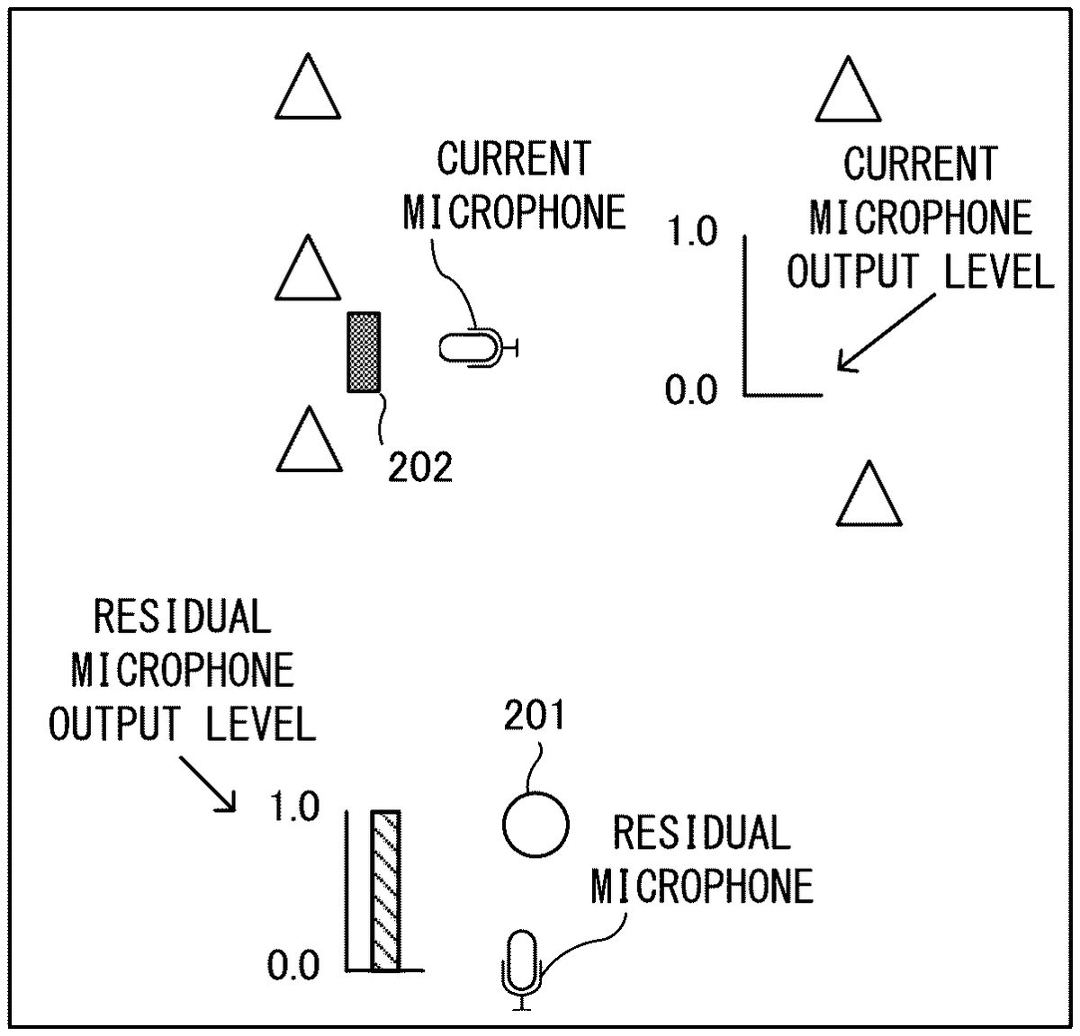
In order to deal with the above problems regarding the manner in which the sound is heard, the following control is performed in the exemplary embodiment. First, in the exemplary embodiment, since the virtual microphone is set at the same position as the position of the virtual camera, the timing of the occurrence of an instantaneous change in camera position and the timing of the occurrence of an instantaneous change in microphone position are substantially the same. When an instantaneous change in microphone position along with an instantaneous change in camera position occurs as described above, a plurality of (two in this example) virtual microphones are temporarily set. Specifically, a virtual microphone after the instantaneous change in microphone position is referred to as “current microphone” (in other words, it can be said that the position of the current microphone is changed instantaneously). Next, a virtual microphone is newly generated at the position of the virtual microphone immediately before the instantaneous change in microphone position occurs, and this virtual microphone is referred to as a “residual microphone”. As a result, as shown inFIG.7, as the virtual microphones, two virtual microphones, that is, the “current microphone” and the “residual microphone”, exist temporarily. As for a sound output signal to the speaker6, while the two virtual microphones exist, a sound signal obtained by combining output from the current microphone to the speaker6and output from the residual microphone to the speaker6is outputted as a game sound to the speaker6.
Furthermore, in the exemplary embodiment, a parameter called “output level” is set for each virtual microphone. In the exemplary embodiment, this parameter is a parameter indicating the degree of output when the virtual microphone outputs a sound acquired from the sound source202, to the speaker6. In other words, the parameter is a parameter that specifies the ratio of input to the virtual microphone (from a predetermined sound source) and output to the speaker6. In the exemplary embodiment, the output level is specified in the range of “0.0” to “1.0”. If the output level is “1.0”, the sound inputted to the virtual microphone (the volume of the sound acquired by the virtual microphone) is outputted to the speaker6at 100% output. If the output level is “0.0”, the sound inputted to the virtual microphone is not outputted to the speaker6(0% output).
In the exemplary embodiment, a process of switching (a main target of sound processing) from the residual microphone to the current microphone over a predetermined period of time is performed. Hereinafter, such switching of the virtual microphone is referred to as microphone switching (as described later, in the exemplary embodiment, microphone switching is completed in 0.3 seconds). Specifically, the output levels of the residual microphone and the current microphone are changed so as to crossfade over time. In the exemplary embodiment, the output level of the residual microphone is changed so as to fade out from “1.0” to “0.0”, and the output level of the current microphone is changed so as to fade in from “0.0” to “1.0”. Then, when the microphone switching is completed, the residual microphone is deleted.
One example of control will be described with reference to the drawings. First,FIG.7shows a state immediately after an instantaneous change in microphone position occurs. In this state, the output level of the residual microphone is set to “1.0”, and the output level of the current microphone is set to “0.0”. In this state, only the sound of the sound source202acquired by the residual microphone can be outputted to the speaker6.
After that, the output level of each virtual microphone changes over time. For example,FIG.8shows a state after 0.1 seconds from the occurrence of the instantaneous change in microphone position.FIG.8shows a state where the output level of the residual microphone has faded out to “0.7” and the output level of the current microphone has faded in to “0.3”. In this state, the sound of the sound source202acquired by the residual microphone is outputted at a volume (intensity) that is 70% of the volume (intensity) at the time when the sound is acquired, and the sound of the sound source202acquired by the current microphone is outputted at a volume that is 30% of the volume at the time when the sound is acquired. Then, the sound actually outputted from the speaker6is a sound obtained by combining the output of the current microphone and the output of the residual microphone.
Furthermore, after 0.3 seconds from the occurrence of the instantaneous change in microphone position, the output level is as shown inFIG.9. InFIG.9, the output level of the residual microphone is “0.0” as a result of further fading-out. In addition, the output level of the current microphone is “1.0” as a result of further fading-in. In this state, only the sound of the sound source202acquired by the current microphone is outputted to the speaker6. In such a state, the residual microphone whose output level has reached “0.0” is deleted. Accordingly, as shown inFIG.10, only the current microphone exists as the virtual microphone, and the microphone switching is completed. Thereafter, sound output control using only the current microphone is performed (until the next instantaneous change in microphone position occurs).
Here, in the exemplary embodiment, as described above, the microphone switching is completed in 0.3 seconds. This is the time that takes into consideration the balance between the sound actually heard by the user and the processing load. As described above, in the microphone switching, the number of temporary virtual microphones is increased, and processing is required for a plurality of virtual microphones, which temporarily increases the processing load. Therefore, it is basically preferable if the time for the microphone switching is shorter. On the other hand, if this time is excessively short, the outputted sound may be heard so as to be choppy or noisy. When the time that does not make the user uncomfortable about the manner in which the sound is heard is examined in consideration of the balance between both, it is conceivable to complete the microphone switching within a range of about 0.1 to 0.8 seconds. Therefore, in the exemplary embodiment, as an example, the case of completing the microphone switching in 0.3 seconds is used as an example.
Moreover, as for the changes in the output levels over time, in the exemplary embodiment, one output level is increased by an amount by which the other output level is decreased, and the output levels are changed such that the total of the output levels is constant. For example, in the example inFIG.8, the output level of the current microphone is increased by an amount (0.3) by which the output level of the residual microphone is decreased from “1.0” to “0.7”. Accordingly, the user's auditory sound volume can be kept constant, and the user can be prevented from being made to feel uncomfortable.
As described above, in the exemplary embodiment, when an instantaneous change in microphone position occurs, a plurality of virtual microphones are temporarily provided, and the above-described microphone switching process is performed, whereby an abrupt change in the outputted sound can be suppressed. For example,FIG.11is a schematic diagram showing a change in output sound in waveform when the microphone switching process as in the exemplary embodiment is not performed and the virtual microphone is simply instantaneously moved along with an instantaneous change in camera position. This is the case where the sound source202that has been present at a distance before the movement is changed to a state of being positioned nearby after the movement. In addition,FIG.12is a schematic diagram showing a change in output sound in waveform when the microphone switching process as in the exemplary embodiment is performed. When the virtual microphone is instantaneously moved, a waveform in which the degree of inclination abruptly changes is formed as shown inFIG.11(especially, change within an ellipse). However, when the microphone switching process as in the exemplary embodiment is performed, the waveform changes gently as shown inFIG.12(especially, change within an ellipse). Accordingly, the possibility that the sound is heard like noise can be reduced, and the sense of mismatch between the appearance of the game screen and the heard sound for the user can be suppressed.
Meanwhile, for easy understanding of the description, the example in which there is only one sound source202has been described above. In actual game processing, it is considered that there are a plurality of sound sources202, and the timings at which reproduction of sounds from the respective sound sources202is started are different from each other. For example, a situation, in which a sound A whose reproduction continues before an instantaneous change in microphone position occurs and a sound B whose reproduction is started after the instantaneous change in microphone position are mixed together, is also considered. Also assuming such a case, in the exemplary embodiment, in the above-described microphone switching, a process of assigning and managing “generation” for the virtual microphone and each sound source202is furthermore performed. Hereinafter, an outline of the processing using this “generation” will be described.
First, the necessity of such a process using the “generation” (situation in which such a process is needed) will be described.FIG.13is a schematic (overhead) view of one example of a game space in a state before an instantaneous change in microphone position occurs. InFIG.13, a first sound source211and a second sound source212exist, and a state where a predetermined sound is reproduced from each sound source is shown. The volumes of the sounds reproduced from both sound sources are the same. In addition, the virtual microphone is placed near the first sound source211. Although not shown, the virtual camera is placed at the same position as the virtual microphone. According to the positional relationship between the virtual microphone and each sound source in this state, a state where, at the position of the virtual microphone, the sound of the first sound source211is heard louder and the sound of the second sound source212is heard relatively quiet, is assumed. Lightning bolt-like symbols near each sound source inFIG.13indicate, by their sizes, the loudness of the sound that would be heard by the virtual microphone.
Next,FIG.14illustrates an example of a game space in a state immediately after the instantaneous change in microphone position occurs. In addition, here, for easy understanding of the description, a description will be given assuming the case where the above-described microphone switching process is not performed and the virtual microphone is simply moved to the position of the virtual camera. In the state inFIG.14, the virtual microphone is positioned near the second sound source212. In such a positional relationship, as for the manner in which the sound from each sound source is heard at the position of the virtual microphone, a state where the sound of the first sound source211is heard quiet and the sound of the second sound source212is heard loud, is assumed. That is, when a change in positional relationship fromFIG.13toFIG.14occurs, the following change is expected as a change in the volume of the sound of each sound source before and after the instantaneous change in microphone position. Specifically, the volume of the sound of the first sound source211is expected to change from loud to quiet, and the volume of the sound of the second sound source212is expected to change from quiet to loud. Then, in such a change in sound volume, in order to change the sound volume such that the sound does not become noise, in the exemplary embodiment, the microphone switching process in which the output levels of the two virtual microphones are crossfaded is performed as described above.
The above is the description of the sound source from which the sound has been reproduced before the instantaneous change in microphone position occurs. Next, a sound source whose reproduction is started after an instantaneous change in microphone position occurs, is considered.FIG.15illustrates an example of a game space in a state before an instantaneous change in microphone position occurs, andFIG.16illustrates an example of a game space in a state immediately after the instantaneous change in microphone position occurs. In bothFIG.15andFIG.16, a third sound source213and a fourth sound source214are shown. The virtual microphone and the virtual camera which is not shown but located at the same position as the virtual microphone are located near the fourth sound source214inFIG.15, and are moved to a position near the third sound source213inFIG.16. In addition, each sound source starts sound reproduction at the same timing and at the same volume immediately after the instantaneous change in microphone position occurs. In such a case, as for the manner in which the sound is heard at the position of the virtual microphone inFIG.16, a state where the sound from the third sound source213is heard loud (sound heard from a near position) and the sound from the fourth sound source214is heard quiet (sound heard from a far position) is expected. In particular, considering that this state is a state where movement of the virtual camera has been completed, the third sound source213in the game screen taken by the virtual camera is seen in front of the user. Since the third sound source213begins to sound in front of the user, as for the volume of the sound of the third sound source213, the output level may be set to “1.0” from the beginning, without fading in the output level as described above. In addition, as for the fourth sound source214(sound reproduced at a distance), if control of fading out the output level is performed for the volume of the sound of the fourth sound source21since the position of the virtual microphone before the instantaneous change in microphone position is nearby, the sound may sound unnatural. It is conceivable to consider such a manner in which the sound is expected to be heard from the sound source whose reproduction is started after an instantaneous change in microphone position occurs. Therefore, in the exemplary embodiment, in addition to the above-described process, the process using the “generation” is also performed as described below.
Next, an outline of the process using the “generation” in the exemplary embodiment will be described. In this process, the generation is divided, based on the timing of the occurrence of an instantaneous change in microphone position (instantaneous change in camera position), into the sound source (hereinafter, referred to as past sound source) from which a sound has been reproduced before the instantaneous change in microphone position and the sound source (hereinafter, referred to as current sound source) whose reproduction is started after the occurrence of the instantaneous change in microphone position. Then, after setting the above output level for each generation, the above-described microphone switching process is performed. Specifically, for the past sound source, the above-described microphone switching process is performed. That is, using both the residual microphone and the current microphone, the output level of each virtual microphone is crossfaded. Meanwhile, for the current sound source, sound processing is performed using only the current microphone. In other words, control, in which the above-described microphone switching process in which the output levels are crossfaded is performed for only the past sound source and the microphone switching process is substantially not performed for the current sound source, is performed. More specifically, until the microphone switching is completed, for the residual microphone, the output level is fixed at “0.0” for the current sound source, and the output level is changed (faded out) over time for the past sound source. That is, the residual microphone does not output any sound of the current sound source to the speaker6(even if a sound is acquired). Meanwhile, for the current microphone, the output level is fixed at “1.0” for the current sound source, and the output level is changed (faded in) over time for the past sound source. That is, the current microphone does not change the volume of the sound of the current sound source, and outputs the sound of the current sound source to the speaker6with the volume of the acquired sound remaining unchanged. In the exemplary embodiment, in order to achieve such control, the concept of “generation” is used. For example, a generation before the occurrence of an instantaneous change in microphone position is defined as a “first generation”, a generation after the occurrence of an instantaneous change in microphone position is defined as a “second generation”, and each sound source is caused to belong to one of the generations according to the timing of the start of reproduction of the sound source. Then, the above-described microphone switching process is performed using output levels that are set for each generation.
An example of setting the above-described “generation” and “output level” will be described with reference toFIG.17toFIG.20. First,FIG.17is a schematic diagram showing a relationship between the virtual microphone and the sound source before an instantaneous change in microphone position occurs. In this state, there is only one current microphone as the virtual microphone. In addition, there is only one sound source A as the sound source (from which a sound is being reproduced). As for the generation, at this time, the “first generation” is set for both the current microphone and the sound source A. In addition, the current microphone is associated with the output level as described above, and this output level is set for each sound source generation. In the example inFIG.17, “1.0” is set as an output level for a “first-generation sound source”. Therefore, the sound from the sound source A (first-generation sound source) acquired by the current microphone is outputted to the speaker6at an output level of “1.0”.
Next,FIG.18shows a state before microphone switching is completed after the instantaneous change in microphone position occurs. Therefore, two virtual microphones, that is, a residual microphone and a current microphone, temporarily exist. In addition, the reproduction from the sound source A continues. InFIG.18, as for the current microphone, the position thereof changes so as to follow the movement of the virtual camera. Then, as for the generation, the generation of the sound source A is still the first generation, and the sound source A corresponds to the above “past sound source” according to the relationship before and after the instantaneous change in microphone position occurs. In addition, for the current microphone, the “second generation” is set as a generation. As for the residual microphone, the “first generation” is set as a generation. Moreover, as an output level that is set for each virtual microphone, an output level for a first-generation sound source and an output level for a second-generation sound source are set (since a second-generation virtual microphone exists). Among them, the output level for a first-generation sound source is changed so as to crossfade over time. Meanwhile, the output level for a second-generation sound source is set to “0.0” as a fixed value for the residual microphone. That is, for the residual microphone, control in which, even if a second-generation sound source appears in the future, a sound reproduced by this second-generation sound source is not outputted to the speaker6, is performed. In other words, for the residual microphone, control in which the sound of a second-generation sound source is substantially not acquired is performed. In contrast, for the current microphone (which has become a second-generation microphone), the output level for a second-generation sound source is set to “1.0” as a fixed value. Therefore, for the current microphone, control in which the sound reproduced by a second-generation sound source is outputted to the speaker6with the volume of the acquired sound remaining unchanged, without particularly changing the volume of the sound, is performed.
Next,FIG.19shows a state where a sound source B which newly starts reproduction is added from the state inFIG.18. Since the sound source B starts reproduction after the instantaneous change in microphone position occurs, the “second generation” (which is the same as the current microphone at that time) is set for the sound source B. That is, the sound source B corresponds to the above “current sound source” according to the relationship before and after the instantaneous change in microphone position occurs. Then, in the state inFIG.19, as for the sound of the sound source A, the output level of each virtual microphone for a first-generation sound source is being changed so as to crossfade, and the sound of the sound source A is outputted to the speaker6by each virtual microphone on the basis of this output level. Meanwhile, as for the sound of the sound source B, the output level of the residual microphone for a second-generation sound source is “0.0”, so that the sound of the sound source B is not outputted from the residual microphone to the speaker6. That is, the residual microphone substantially does not pick up the sound of the sound source B. In contrast, the output level of the current microphone for a second-generation sound source is “1.0”, so that the current microphone outputs the sound from the sound source B to the speaker6with the volume of the sound remaining unchanged.
FIG.20shows a state when the time has further passed from the state inFIG.19and the microphone switching has ended. Specifically, the output level for a first-generation sound source is “0.0” at the residual microphone, and is “1.0” at the current microphone. Both of the sound sources A and B continue reproduction. In this state, no sound is outputted from the residual microphone to the speaker6, and the sounds of the sound source A and the sound source B are processed only with the current microphone.
As described above, the generation is divided based on the timing of the occurrence of an instantaneous change in microphone position, the output level for the past sound source is crossfaded, and the output level for the current sound source is fixed without performing such crossfade. Accordingly, even if there is a sound source whose reproduction is started immediately after an instantaneous change in microphone position, it is possible to achieve a hearing manner that does not give an uncomfortable feeling.
[Details of Game Processing of Exemplary Embodiment]
Next, the game processing in the exemplary embodiment will be described in more detail with reference toFIG.21toFIG.29.
[Data to be Used]
First, various kinds of data to be used in the game processing will be described.FIG.21illustrates a memory map showing an example of various kinds of data stored in the storage section84of the game apparatus2. The storage section84includes a program storage area301and a data storage area303. In the program storage area301, a game processing program302is stored. In addition, in the data storage area303, sound source data304, virtual microphone data305, virtual camera data306, current microphone specification data307, event scene definition data308, operation data309, etc., are stored.
The game processing program302is a program for executing the game processing according to the exemplary embodiment, and also includes a program code for executing the above-described control for the virtual microphone.
The sound source data304is data regarding the sound sources202.FIG.22illustrates an example of the data structure of the sound source data304. The sound source data304is a database that includes at least a sound source ID341, reproduction sound data342, sound source position-orientation data343, a sound source generation ID344, and a reproduction flag345. The sound source ID341is an ID for uniquely identifying each sound source. The reproduction sound data342is sound data based on which a sound is reproduced. The sound source position-orientation data343is data indicating the position and the orientation of the sound source202in the virtual game space. The sound source generation ID344is data indicating the above “generation” to which the sound source belongs, and a predetermined generation number is stored. In addition, the content of the sound source generation ID344is updated at the timing when sound reproduction is started by the sound source. The reproduction flag345is data indicating whether the sound source is reproducing the sound of the reproduction sound data342.
Referring back toFIG.21, the virtual microphone data305is data regarding the virtual microphones.FIG.23illustrates an example of the data structure of the virtual microphone data305. The virtual microphone data305is a database that has items such as a microphone generation ID351, a residual flag352, a switching flag353, a switching completion flag354, microphone position-orientation data355, and an output level specification table356.
The microphone generation ID351is an ID indicating the generation of the virtual microphone. In the exemplary embodiment, the number of residual microphones generated temporarily as described above along with the occurrence of an instantaneous change in microphone position is only one. Therefore, the virtual microphone and the microphone generation ID351are associated with each other in a one-to-one relationship. That is, in the exemplary embodiment, the microphone generation ID351also serves to uniquely identify a plurality of virtual microphones.
The residual flag352is a flag for indicating whether the virtual microphone corresponds to a residual microphone. If the residual flag352is ON, it indicates that the virtual microphone is a residual microphone, and if the residual flag352is OFF, it indicates that the virtual microphone is a current microphone.
The switching flag353is a flag for indicating whether the virtual microphone is in a state during the microphone switching. If the switching flag353is ON, it indicates that the virtual microphone is in a state during the microphone switching, and if the switching flag353is OFF, it indicates that the virtual microphone is not in a state during the microphone switching.
The switching completion flag354is a flag for indicating the virtual microphone that is in a state immediately after the microphone switching is completed. The switching completion flag354is set to be ON when the microphone switching for the virtual microphone is completed. The switching completion flag354is used for determining the necessity of processing at the time of switching completion described later.
The microphone position-orientation data355is data for indicating the current position of the virtual microphone (each of the current microphone and the residual microphone) in the virtual game space. In addition, the microphone position-orientation data355also includes information indicating the orientation of the virtual microphone.
The output level specification table356is data for specifying the output level of the virtual microphone for each sound source generation. Specifically, the output level specification table356is data in a table format including items such as a sound source generation357and output level data358. The sound source generation357is data for specifying the generation of each sound source, and the output level data358is data that specifies an output level for the sound source of the generation. In addition, the output level data358is also data whose content can be changed over time as described above, depending on the generation of the sound source. In consideration of the case where an instantaneous change in microphone position (camera position) occurs in multiple stages, the output level specification table356may be treated as data in a ring buffer format. For example, the number of buffers may be set to 4, and data from the newest generation to the generation previous to the newest generation by four generations may be stored. Then, when an instantaneous change in microphone position occurs, the data may be updated in the order from the oldest.
Referring back toFIG.21, the virtual camera data306is data that specifies the current position, orientation, angle of view, etc., of the virtual camera.
The current microphone specification data307is data that specifies which virtual microphone is the current microphone at the current time. In a state where the microphone switching process is not being performed, only one virtual microphone exists, and necessarily becomes a current microphone.
The event scene definition data308is data that defines the contents of the event demonstration scene described above. The event scene definition data308can include data that defines the contents of each of a plurality of event demonstration scenes. The data regarding each event includes the above event start condition, information that defines the movement contents of the player character201and NPCs in the event demonstration scene, information that defines the camera movement of the virtual camera in the event demonstration scene, etc.
The operation data309is data indicating the content of an operation performed on the controller4. In the exemplary embodiment, the operation data309includes data indicating pressed states of the buttons such as the cross key or an input state to the analog stick provided to the controller4. The content of the operation data309is updated in predetermined cycles on the basis of a signal from the controller4.
In addition, various kinds of data to be used in the game processing are stored as necessary in the storage section84. For example, history data of the positions of the virtual camera and the virtual microphone from the last frame to the frame previous to the current frame by several frames, etc., which are used for determining the occurrence of the above instantaneous change in camera position or microphone position, can also be stored.
[Details of Processing Executed by Processor81]
Next, the game processing according to the exemplary embodiment will be described in detail. Here, processing related to the above-described control of the virtual microphone will be mainly described, and other game processing will be briefly described and the detailed description thereof is omitted.
FIG.24is a flowchart showing the details of the game processing according to the exemplary embodiment. A process loop of steps S2to S6shown inFIG.24is repeatedly executed every frame period. In addition, this flowchart is merely an example of the processing. Therefore, the order of each process step may be changed as long as the same result is obtained. In addition, the values of variables and thresholds used in determination steps are also merely examples, and other values may be used as necessary. When the game processing according to the exemplary embodiment is started, first, in step S1, the processor81executes a preparation process. Specifically, the processor81constructs a virtual game space, and places objects such as the player character201, various NPCs, and various sound sources202in the virtual game space as appropriate. Furthermore, the processor81also places the virtual camera and the virtual microphone at a predetermined position (based on the position of the player character201). Accordingly, the virtual camera data306and the virtual microphone data305are also generated. At this time, the number of data sets included in the virtual microphone data305is only one. In addition, a value (initial value of “01”) of the microphone generation ID351is set in the current microphone specification data307. Furthermore, the processor81takes an image of the virtual game space by the virtual camera to generate a game image, and generates a game sound on the basis of the sounds of the various sound sources202acquired by the virtual microphone. Then, the processor81outputs the game image to the display unit5, and outputs the game sound to the speaker6.
Next, in step S2, the processor81acquires the operation data309.
Next, in step S3, the processor81executes various kinds of game processing. Here, the following processing is mainly performed. First, the processor81determines whether the current state is during an event demonstration scene. If the current state is not during an event demonstration scene, the processor81executes a movement control process for the player character201on the basis of the operation data309. Furthermore, accordingly, the processor81also executes various kinds of game processing such as contact determination processing. As a result of moving the player character201, if the player character201has come into contact with an object of the warp gimmick described above, a process of further changing the current position of the player character201is performed on the basis of the warp gimmick. In addition, the processor81also determines whether the event start condition has been satisfied. Examples of the event start condition include a condition that the player character201has reached a predetermined position, and a condition that the player character201has spoken to a predetermined NPC. If the event start condition has been satisfied, the processor81executes a process for transition to an event demonstration scene. On the other hand, if the current state is during an event demonstration scene, the processor81automatically controls the movement of various characters on the basis of the contents of the event scene definition data308. Furthermore, the processor81also determines whether the event demonstration scene has ended. If the event demonstration scene has ended, the processor81shifts to a game mode in which the movement control process for the player character201is executed on the basis of the operation data309as described above.
Next, in step S4, the processor81executes a virtual camera-related process. In this process, an image of the virtual game space in which the result of the game processing is reflected is taken by the virtual camera and outputted to the display unit5. Specifically, first, the processor81determines whether the current state is during an event demonstration scene. Then, if the current state is during an event demonstration scene, the processor81performs movement control for the virtual camera on the basis of the contents of the event scene definition data308. As a result, the above-described instantaneous change in camera position may occur during the event demonstration scene. The case immediately after the start of the event demonstration scene corresponds to a state “during an event demonstration scene”, and the virtual camera is moved to the position defined as the position at the start of the event demonstration scene. As a result, the above-described instantaneous change in camera position may occur as the event demonstration scene starts. On the other hand, if the current state is not during an event demonstration scene, the processor81performs movement control such that the virtual camera follows the player character201, on the basis of the position of the player character201. In addition, along with the above-described movement control for the virtual camera, the contents (current position, etc.) of the virtual camera data306are also updated as appropriate. Then, the processor81takes an image of the virtual game space by the virtual camera to generate a game image, and outputs the game image to the display unit5.
Next, in step S5, the processor81executes a virtual microphone-related process. In this process, while the above-described microphone switching process is performed as appropriate, the sound of each sound source202acquired by the virtual microphone is outputted to the speaker6.
[Sound Source Reproduction Process]
FIG.25is a flowchart showing the details of the virtual microphone-related process. InFIG.24, first, in step S11, the processor81executes a sound source reproduction process. This process is a process for reproducing a predetermined sound from each sound source that exists in the virtual game space.FIG.26is a flowchart showing the details of the sound source reproduction process. InFIG.26, first, in step S21, the processor81selects one sound source202as a target of the processing described below, from among the sound sources202in the virtual game space. Hereinafter, the selected sound source202is referred to as a processing target sound source. The method for this selection may be any method. For example, the sound sources202that exist in a predetermined range centered on the virtual microphone may be extracted, and selected in the order from the one having the smallest sound source ID341.
Next, in step S22, the processor81determines whether the current state is a state where the processing target sound source is reproducing a predetermined sound, on the basis of the reproduction flag345. If the current state is not a state of reproducing a predetermined sound (NO in step S22), in step S23, the processor81determines whether a predetermined condition for starting sound reproduction (hereinafter, referred to as a reproduction start condition) has been satisfied for the processing target sound source. As a result of the determination, if the reproduction start condition has been satisfied (YES in step S23), in step S24, the processor81sets the same value (generation number) as the microphone generation ID351of the current microphone at this time, as the sound source generation ID344of the processing target sound source.
Next, in step S25, the processor81sets the reproduction flag345to be ON for the processing target sound source.
Next, in step S26, the processor81starts reproduction of the predetermined sound corresponding to the processing target sound source, on the basis of the reproduction sound data342of the processing target sound source. Then, the processor81advances the processing to step S30described later.
On the other hand, as a result of the determination in step S23, if the reproduction start condition has not been satisfied (NO in step S23), the processor81advances the processing to step S30described later.
Next, the processing performed if, as a result of the determination in step S22, it is determined that the current state is a state where the processing target sound source is reproducing a predetermined sound (YES in step S22), will be described. In this case, in step S27, the processor81determines whether a predetermined condition for stopping reproduction (hereinafter, referred to as a reproduction stop condition) has been satisfied for the processing target sound source. As a result of the determination, if the reproduction stop condition has not been satisfied (NO in step S27), the processor81advances the processing to step S26, and continues the process of reproducing the predetermined sound.
On the other hand, if the reproduction stop condition has been satisfied (YES in step S27), in step S28, the processor81stops the sound reproduction process for the processing target sound source. In subsequent step S29, the processor81clears the sound source generation ID344of the processing target sound source (sets a Null value), and sets the reproduction flag345to be OFF.
Next, in step S30, the processor81determines whether the above processes have been performed for all the sound sources202. If any unprocessed sound source202remains (NO in step S30), the processor81returns to step S21, selects the next processing target sound source, and repeats the processes. On the other hand, if the above processes have been performed for all the sound sources202(YES in step S30), the processor81ends the sound source reproduction process.
[Processing when Instantaneous Change in Microphone Position Occurs]
Referring back toFIG.25, next, in step S12, the processor81performs a virtual microphone (current microphone) movement process. In the virtual camera-related process, the contents of the virtual camera data306can be updated as appropriate (so as to follow the position of the player character201). The processor81performs a process of referring to the virtual camera data306and moving the current microphone by setting the content of the microphone position-orientation data355of the current microphone to the same position as the current virtual camera.
Next, in step S13, the processor81determines whether an instantaneous change in microphone position has occurred. In the exemplary embodiment, if the above instantaneous change in camera position has occurred, it substantially means that an instantaneous change in microphone position has occurred. Therefore, for example, whether an instantaneous change in microphone position has occurred can be determined on the basis of whether or not the difference in distance between the position at the last frame and the current position of the virtual camera or the virtual microphone is equal to or greater than a predetermined value. As a result of the determination, if an instantaneous change in microphone position has not occurred (NO in step S13), the processor81advances the processing to step S15described later. If an instantaneous change in microphone position has occurred (YES in step S13), in step S14, the processor81executes a microphone switching preparation process. In this process, mainly, the above-described generation of a residual microphone and setting of the output level specification table356are performed.
FIG.27is a flowchart showing the details of the microphone switching preparation process. InFIG.27, first, in step S41, the processor81performs a setting process for the current microphone. Specifically, the processor81sets a generation higher by one, as the microphone generation ID351of the virtual microphone. For example, if the microphone generation ID351has been “01”, the processor81sets “02” as the microphone generation ID351. Next, the processor81sets the newly set microphone generation ID351in the current microphone specification data307. Next, the processor81sets the contents of the output level specification table356(for the current microphone). Since the virtual microphone is a current microphone, the processor81sets “1.0” as a fixed value in the output level data358for the generation sound source202having the same value as (or a value higher than) the microphone generation ID351of the current microphone. In this case, data of the generation corresponding to the newly set microphone generation ID351is added to the output level specification table356. In addition, if the output level specification table356is already filled with data for four generations, the data is replaced in the order from the oldest. On the other hand, the processor81sets “0.0” as the output level data358for the generation sound source202having a value less than the microphone generation ID351of the current microphone itself. The value of the output level data358set here changes toward “1.0” over time. Moreover, the processor81sets the switching flag353to be ON for the current microphone, and sets the switching completion flag354to be OFF for the current microphone.
Next, in step S42, the processor81executes a process of generating a residual microphone at the position of the current microphone before movement. Specifically, the processor81generates data having the following contents, and adds the generated data to the virtual microphone data305. First, as the microphone generation ID351, the microphone generation ID351of the current microphone before movement is set (a generation previous by one to the generation of the current microphone at the current time). In addition, the residual flag352and the switching flag353are set to be ON, and the switching completion flag354is set to be OFF. The position of the current microphone before movement is set in the microphone position-orientation data355. In the output level specification table356, “0.0” is uniformly set as a fixed value for sound source generations newer than the generation of the residual microphone itself. “1.0” is set as an initial value for sound source generations each of which is the same as or older than the generation of the residual microphone itself. This value is a value that changes over time.
Next, in step S43, the processor81calculates the volume of the sound from each sound source202acquired by the residual microphone at this time, on the basis of the positional relationship (distance, etc.) between the residual microphone and the sound source202(the sound source202that is reproducing a sound) of the same generation as the residual microphone. Hereinafter, this volume is referred to as a residual basic volume. In addition, the residual basic volume is treated as the volume when the output level of the residual microphone is “1.0”. Here, in the processing described later, a process of gradually decreasing the volume from the residual basic volume over time is performed. Here, if the sound source202is, for example, an autonomously movable object or the like, the position of the sound source202may change with respect to the residual microphone until the microphone switching is completed. In this regard, in the exemplary embodiment, such a change in positional relationship is not taken into consideration, and a volume corresponding to the above output level is calculated based on the above residual basic volume. That is, until the microphone switching is completed, a process of gradually decreasing the volume with the residual basic volume calculated here being used as a base, is performed regardless of whether or not the position of the sound source202changes with respect to the residual microphone. This is due to the viewpoint of reducing the processing load. That is, if, also during the microphone switching the process is performed such that a change in the position of the sound source with respect to the residual microphone is reflected, the processing load may be increased, so that such a residual basic volume is used as a reference. In addition, this is considered to be because, since the microphone switching is completed in a short time of 0.3 seconds as described above, even if the process is performed using such a residual basic volume, the user is not made to feel uncomfortable.
When the process in step S43ends, the processor81ends the microphone switching preparation process.
[Processing During Microphone Switching]
Referring back toFIG.25, next, in step S15, the processor81refers to the switching flag353in the virtual microphone data305, and determines whether there is a virtual microphone for which the microphone switching process is being performed. As a result of the determination, if there is no virtual microphone for which the microphone switching process is being performed (NO in step S15), the processor81advances the processing to step S17described later. On the other hand, if there is a virtual microphone for which the microphone switching process is being performed (YES in step S15), in step S16, the processor81executes the microphone switching process.
FIG.28is a flowchart showing the details of the microphone switching process. First, in step S51, the processor81determines whether a condition for completing the microphone switching has been satisfied. Specifically, the processor81determines whether the output level data358of the residual microphone is all “0.0” for the sound source of each generation, and the output level data358of the current microphone is all “1.0” for the sound source of each generation. That is, the processor81determines whether the current state is a state where the sound outputted to the speaker6is only from the current microphone. As a result of the determination, if the condition for completing the microphone switching has not being satisfied yet (NO in step S51), next, in step S52, the processor81updates the contents of the output level data358such that the output levels of the current microphone and the residual microphone crossfade according to the time elapsed from the occurrence of the instantaneous change in microphone position. That is, for the current microphone, the processor81updates the output level data358for the sound source generation357less than the microphone generation ID351(that is, of the past sound source) so as to gradually fade in from “0.0” toward “1.0” (over 0.3 seconds in this example). In addition, the output level data358for the other sound source generation357(of the current sound source) is kept fixed at “1.0”. Moreover, for the residual microphone, the processor81updates the output level data358for the same sound source generation357(past sound source) as the microphone generation ID351so as to gradually fade out from “1.0” toward “0.0” (over 0.3 seconds). In addition, the output level data358for the sound source generation357(the current sound source) newer than the generation of the residual microphone itself, is kept fixed at “0.0”. Then, the processor81ends the microphone switching process.
On the other hand, as a result of the determination in step S51, if the condition for completing the microphone switching has been satisfied (YES in step S51), in step S53, the processor81sets the switching flag353to be OFF for the residual microphone and the current microphone for which the completion condition has been satisfied.
Next, in step S54, the processor81sets the switching completion flag354to be ON for the residual microphone and the current microphone for which the condition for completing the microphone switching has been satisfied. Then, the processor81ends the microphone switching process.
[Processing Performed Immediately after Completion of Microphone Switching]
Referring back toFIG.25, next, in step S17, the processor81determines whether there is a virtual microphone for which the switching completion flag354is ON. As a result of the determination, if there is no virtual microphone for which the switching completion flag354is ON (NO in step S17), the processor81advances the processing to step S19described later. If there is a virtual microphone for which the switching completion flag354is ON (YES in step S17), in step S18, the processor81executes a switching completion-time process. In the switching completion-time process, a generation merging process and a process of deleting the residual microphone are mainly performed.
Here, an outline of the generation merging process performed in the switching completion-time process will be described. In this process, after the microphone switching is completed, the sound source generation ID344for the sound source202of an old generation is updated with that of a new generation. That is, a process of merging the generation of the sound source202with the latest one is performed.FIG.29shows the concept of the switching completion-time process.FIG.29is also an example of setting of “generation” and “output level” afterFIG.20. InFIG.29, the sound source generation of the sound source A is updated from “1” to “2”. Accordingly, the sound source generations of both the sound sources A and B are made uniform to be second generation. As a result, only the output level of the current microphone for a second-generation sound source is used. Therefore, in the exemplary embodiment, a process of clearing the contents of the sound source generation357and the output level data358for a “first-generation sound source” (no longer used) of the current microphone (setting Null) is also performed. Furthermore, a process of deleting the data for the residual microphone from the virtual microphone data305is also performed.
FIG.30is a flowchart showing the details of the switching completion-time process. First, in step S61, the processor81refers to the virtual microphone data305and extracts the virtual microphone for which the switching completion flag354is ON.
Next, in step S62, the processor81extracts the sound source202of the same generation as the microphone generation ID351of the residual microphone, from the sound source data304. Then, the processor81updates the sound source generation ID344of the extracted sound source to the same generation as the microphone generation ID351of the current microphone.
Next, in step S63, the processor81clears the data (the sound source generation357and the output level data358) for the sound source generation corresponding to the microphone generation ID351of the residual microphone for which the switching is completed this time, from the output level specification table356for the current microphone (sets Null).
Next, in step S64, the processor81deletes the data for the residual microphone for which the microphone switching is completed this time, from the virtual microphone data305.
Next, in step S65, the processor81sets the switching completion flag354to be OFF for the current microphone. This is the end of the switching completion-time process.
[Process of Outputting Sound to Speaker6]
Referring back toFIG.25, next, in step S19, the processor81executes a sound output process. Specifically, if there is a residual microphone, that is, if the current state is during microphone switching, the processor81calculates the volume of the sound of each sound source that is to be outputted from the residual microphone to the speaker6, on the basis of the contents of the output level specification table356for the residual microphone and the residual basic volume. In addition, for the current microphone, the following process is performed. First, the processor81calculates the volume of the sound from each sound source acquired at the position of the current microphone at this time (hereinafter, referred to as current basic volume). Next, the processor81calculates the volume of the sound of each sound source that is to be outputted from the current microphone to the speaker6, on the basis of the contents of the output level specification table356for the current microphone and the current basic volume. Then, if the current state is during microphone switching, the processor81combines both of the outputs of the residual microphone and the current microphone to generate a sound signal to be outputted to the speaker6, and outputs the sound signal to the speaker6. On the other hand, if the current state is not during microphone switching, the processor81generates a sound signal to be outputted to the speaker6, using only the current microphone, and outputs the sound signal to the speaker6. That is, the processor81performs output to the speaker6at the same volume as the current basic volume. Then, the processor81ends the virtual microphone-related process.
As for the current basic volume, in another exemplary embodiment, the same process as that for the above-described residual basic volume may be performed. That is, until the microphone switching is completed, even if the position of the sound source changes with respect to the current microphone, the process may be performed without taking into consideration this position change.
Referring back toFIG.24, next, in step S6, the processor81determines whether a condition for ending the game processing has been satisfied. For example, the processor81determines whether a game end instruction operation has been performed by the user. If this condition has not been satisfied (NO in step S6), the processor81returns to step S2and repeats the processes. On the other hand, if this condition has been satisfied (YES in step S6), the processor81ends the game processing.
This is the end of the detailed description of the game processing according to the exemplary embodiment.
As described above, in the exemplary embodiment, if the position of the virtual microphone (virtual camera) is instantaneously and considerably moved, a virtual microphone is provided at each of positions before and after movement, so that a plurality of virtual microphones exist temporarily. Then, the output level from each virtual microphone to the speaker6is changed so as to crossfade. Accordingly, an abrupt change in the sound outputted from the speaker6can be suppressed, and the user can be prevented from hearing the outputted sound such that noise is included therein.
MODIFICATIONS
In the above embodiment, the case where the number of virtual cameras is one has been described as an example. In another exemplary embodiment, a plurality of virtual cameras and a plurality of virtual microphones may be prepared, and control in which a virtual camera and a virtual microphone (current camera/current microphone) to be used are switched according to whether or not it is an event demonstration scene may be performed. For example, a game camera which is a normally used virtual camera and moves so as to follow the player character201, and two virtual cameras which are event cameras used exclusively for an event demonstration scene, are placed in a virtual space. In addition, virtual microphones (game microphone, event microphones) are placed at the same positions as the virtual cameras, respectively. Then, control in which only either of these cameras and only either of these microphones are enabled is performed. That is, control may be performed in which the game camera (game microphone) is enabled as the initial state, and when a condition for starting an event demonstration scene is satisfied, the game camera (game microphone) is disabled and the event cameras (event microphones) are enabled. Even when switching the current camera/current microphone among the plurality of virtual cameras/virtual microphones, it is possible to apply the above-described virtual microphone switching process. In such a case, if the change in the position of the current camera/current microphone is greater than a predetermined distance, it means that the above condition for an instantaneous change in camera position/instantaneous change in microphone position is satisfied. In addition, in the case of performing such control, instead of “generating/deleting” the residual microphone, it is sufficient to perform control in which the residual microphone is “enabled/disabled”, for example. In other words, it is sufficient to perform control in which the role of the current microphone and the role of the residual microphone are switched between the game microphone and the event microphones.
In the above embodiment, as one example of the condition for starting the microphone switching process, the occurrence of an instantaneous change in microphone position, that is, a change in the position of the virtual microphone before and after one frame being equal to or greater than a predetermined distance, has been described. In addition, the following conditions may be used as the condition for starting the microphone switching process. For example, when the process related to warp is performed as described above, it may be determined that the condition for starting the microphone switching process is satisfied (regardless of the magnitude of the actual movement distance). Moreover, when a condition for the player character201to move at a high speed is satisfied, and control in which the player character201is moved at a high speed is performed, it may be determined that the condition for starting the microphone switching process is satisfied (regardless of the magnitude of the actual movement distance). Specifically, this is the case where a command for the player character201to move at a higher speed than the movement speed at the time of normal movement is inputted. Furthermore, this is the case where, even in the absence of such a command input, a condition for high-speed movement is satisfied (for example, the case where the player character201is on a “floor that allows sliding at a high speed in an arrow direction”), and high-speed movement control of the player character201is actually performed. Moreover, in the case where a plurality of virtual cameras are prepared as described above, when switching is performed from the game camera (microphone) to the event camera (microphone) as described above, the above-described microphone switching process may be performed uniformly regardless of the magnitude of the distance between both cameras.
As another example of the condition for starting the microphone switching process, when using the warp gimmick described above, for example, the microphone switching process may be started when a position away from the current position by a predetermined distance or more is specified as the warp destination. That is, when the warp destination is specified without calculating the actual movement distance after warp, it may be determined that the condition for starting the microphone switching process is satisfied.
During reproduction of the event demonstration scene, since the movement content and the movement path of the virtual camera are set in advance, a scene in which the virtual camera instantaneously moves by a predetermined distance or more can also be determined in advance. Therefore, in a scene, in the event demonstration scene, which is preset such that the virtual camera instantaneously moves, microphone switching may be set such that the microphone switching is started in synchronization with the transition to this scene without calculating the movement speed or the like of the virtual camera. In addition, in an embodiment where a plurality of virtual cameras are used as described above, when switching from the game camera to the event camera, it is possible to determine in advance an event in which switching occurs such that the position of the camera to be used is changed instantaneously and considerably, from among a plurality of events that exist. Therefore, an event that involves such an instantaneous change in camera position may be set such that the microphone switching process is executed in synchronization with the start of the event. That is, when a condition for starting an event in which it is known in advance that an instantaneous change in camera/microphone position occurs is satisfied, it may be determined that the condition for the instantaneous change in microphone position is satisfied, without calculating the actual position change or movement speed of the virtual camera or the virtual microphone.
As for setting of the output level specification table356for each virtual microphone, in addition to the above process, for example, data that predefines the contents of the output level specification table356for each virtual microphone generation may be used. For example, output level master data having a data structure shown inFIG.31may be prepared. The output level master data shown inFIG.31is data that predefines the correspondence between sound source generation and initial output level for each virtual microphone generation. When generating the residual microphone and setting the current microphone in the above-described microphone switching preparation process (step S14), such output level master data may be referred to and the output level data358may be set according to the generation of each microphone. By using such output level master data, different output levels can be specified for each virtual microphone generation and each sound source generation, respectively, and it is also possible to perform finer adjustment.
In the above embodiment, the example in which the output level of the residual microphone is decreased from “1.0” as the initial value has been described. The present disclosure is not limited thereto, and in another exemplary embodiment, a process of decreasing the output level of the residual microphone from “0.8” as the initial value may be performed.
In the above embodiment, the case where the output level of the residual microphone reaches “0.0” and the output level of the current microphone reaches “1.0” has been described as an example of the condition for completing the microphone switching. That is, control in which the output levels of the respective virtual microphones are gradually changed with “0.0” and “1.0” as target values has been described as an example. In another exemplary embodiment, for example, when the output level of the residual microphone reaches “0.1” and the output level of the current microphone reaches “0.9”, the microphone switching may be completed. Furthermore, after that, control in which only the current microphone whose output level is set to “1.0” is used may be performed. That is, when a state where the sound outputted to the speaker6is substantially only from the current microphone is brought about, the microphone switching may be completed.
In the above embodiment, the case where the positions of the virtual camera and the virtual microphone are the same, has been illustrated, but in another exemplary embodiment, the positions of the virtual camera and the virtual microphone may be different from each other. For example, the position of the virtual microphone may be the position ahead of the position of the virtual camera by a predetermined distance. Alternatively, the virtual microphone may be provided at the midpoint between the virtual camera and the player character201. In this case, the position of the virtual microphone can also change as the orientation of the virtual camera changes. Therefore, it may be determined that the above instantaneous change in microphone position has occurred, on the basis of the change speed of the orientation of the virtual camera.
In the above embodiment, as for the determination of an instantaneous change in microphone position, the example based on a change in position before and after one frame has been described, but the present disclosure is not limited thereto. In another exemplary embodiment, when, instead of a change in position before and after one frame, a change in position within several frames to several dozen frames satisfies the predetermined condition, it may be determined that the above-described instantaneous change in microphone position has occurred. In addition to such a change in the position of the virtual microphone, the occurrence of an instantaneous change in microphone position may be determined on the basis of a change in acceleration related to movement of the virtual microphone.
As for the value of the output level, the range of “0.0” to “1.0” has been shown as an example, but other values may be used. Other parameters may be used as appropriate as long as these parameters correspond to the output level.
As for the time for completing the microphone switching, the example in which the microphone switching is completed within the range of 0.1 to 0.8 seconds has been described above. In another exemplary embodiment, the microphone switching may be completed in a time that is outside this range. For example, the case where a representation that two images crossfade is performed as a video representation and the above-described microphone switching process is performed in synchronization with this representation, is assumed. In such a case, the time for completing the crossfade of the images and the time for completing the microphone switching (that is, the crossfade of sounds) may be made the same. Therefore, in such a case, a time of 0.8 seconds or more may be set as the time for completing the microphone switching.
As for the output level in the above embodiment, for example, the output level may be further multiplied by another parameter, and then the volume of the sound to be finally outputted to the speaker6may be adjusted. For example, the “basic system (operating system or the like)” that performs basic control of the game apparatus2holds a parameter called “first output level”, and the output level to be determined in the game processing (game application) described in the above embodiment may be calculated as a “second output level”. The final output volume to the speaker6may be based on the value obtained by multiplying the “first output level” by the “second output level”, for example.
In the above embodiment, the example in which, when crossfading the output levels, the output levels are changed in a complementary manner such that the total of the output levels is constant (the total is “1.0”), has been described. In another exemplary embodiment, the output levels do not necessarily have to be changed in a complementary manner. For example, in order to equalize the auditory sound volume, it is also conceivable to keep the power constant instead of the multiplier. In this case, the output levels can be calculated such that the result of squaring and adding together is “1.0”. As an example, at a certain moment, the output level of the residual microphone may be 0.836 (when squared, about 0.7), and the output level of the current microphone may be 0.547 (when squared, about 0.3). Alternatively, for example, in a certain event demonstration scene, a change in the output level of each microphone may be individually set in advance regardless of complementarity.
In the above embodiment, the case where the series of processes according to the game processing are performed in the single game apparatus2has been described. However, in another embodiment, the above series of processes may be performed in an information processing system that includes a plurality of information processing apparatuses. For example, in an information processing system that includes a terminal side apparatus and a server side apparatus capable of communicating with the terminal side apparatus via a network, a part of the series of processes may be performed by the server side apparatus. Alternatively, in an information processing system that includes a terminal side apparatus and a server side apparatus capable of communicating with the terminal side apparatus via a network, a main process of the series of the processes may be performed by the server side apparatus, and a part of the series of the processes may be performed by the terminal side apparatus. Still alternatively, in the information processing system, a server side system may include a plurality of information processing apparatuses, and a process to be performed in the server side system may be divided and performed by the plurality of information processing apparatuses. In addition, a so-called cloud gaming configuration may be adopted. For example, the game apparatus2may be configured to send operation data indicating a user's operation to a predetermined server, and the server may be configured to execute various kinds of game processing and stream the execution results as video/audio to the game apparatus2.
While the exemplary embodiments have been described in detail, the foregoing description is in all aspects illustrative and not restrictive. It is to be understood that numerous other modifications and variations can be devised without departing from the scope of the exemplary embodiments.
Claims
- A computer-readable non-transitory storage medium having stored therein a game program causing a computer of an information processing apparatus, capable of outputting sound data to a speaker, to: place a virtual sound source with which the sound data is associated, in a virtual space;reproduce the sound data on the basis of game processing;move a virtual microphone in the virtual space on the basis of the game processing;set a volume of virtual microphone acquisition sound data virtually acquired by the virtual microphone from the virtual sound source, on the basis of a distance between the virtual microphone and the virtual sound source;set an output level indicating a degree of output of the virtual microphone acquisition sound data to be outputted to the speaker, to a first output level;and when a first condition related to a change in a position of the virtual microphone in the virtual space is satisfied, place a residual virtual microphone at a position of the virtual microphone before the change in the position, and output residual virtual microphone acquisition sound data whose volume is set on the basis of a distance between the residual virtual microphone and the virtual sound source, and current virtual microphone acquisition sound data whose volume is set on the basis of a distance between the virtual microphone after the change in the position and the virtual sound source, to the speaker such that the output level of the residual virtual microphone acquisition sound data is gradually decreased and the output level of the current virtual microphone acquisition sound data is gradually increased toward the first output level.
- The storage medium according to claim 1, wherein the first condition is satisfied when a parameter related to a movement speed of the virtual microphone in the virtual space becomes equal to or greater than a predetermined value.
- The storage medium according to claim 2, wherein the virtual microphone is placed in association with a position and/or an orientation of the virtual camera, and the first condition is satisfied when the parameter related to the movement speed of the virtual microphone becomes equal to or greater than the predetermined value or a parameter related to a change speed of the orientation of the virtual camera becomes equal to or greater than a predetermined value.
- The storage medium according to claim 1, wherein the virtual microphone is placed in association with a position and/or an orientation of the virtual camera, a first virtual camera which is used for reproducing a predetermined scene in which movement of the virtual camera is automatically controlled, and a second virtual camera which is normally used other than for the predetermined scene and whose movement is controlled on the basis of an operation of a user or movement of a player character object are used in the game processing, and when the virtual camera used for generating a game image to be displayed is switched from the second virtual camera to the first virtual camera, the first condition is satisfied.
- The storage medium according to claim 1, wherein the virtual microphone is placed in association with a position and/or an orientation of the virtual camera, and the first condition is satisfied when a predetermined scene in which the virtual camera automatically moves is being reproduced and a preset timing when the virtual camera moves in the virtual space by a predetermined distance at a predetermined speed or more has come.
- The storage medium according to claim 1, wherein the output level of the residual virtual microphone acquisition sound data is gradually decreased from the first output level.
- The storage medium according to claim 1, wherein when the first condition is satisfied, a sound of a past sound source which is a sound source whose reproduction is performed before the first condition is satisfied is outputted to the speaker such that the output level of the residual virtual microphone acquisition sound data is gradually decreased and the output level of the current virtual microphone acquisition sound data is gradually increased toward the first output level, and a sound of a current sound source which is a sound source whose reproduction is started after the first condition is satisfied is outputted to the speaker such that the output level of the current virtual microphone acquisition sound data is not changed from the first output level.
- The storage medium according to claim 7, wherein a sound acquired from the current sound source by the residual virtual microphone is not outputted to the speaker, or the residual virtual microphone is not caused to acquire a sound from the current sound source.
- The storage medium according to claim 1, wherein a time from start of a process of outputting the residual virtual microphone acquisition sound data and the current virtual microphone acquisition sound data to the speaker while changing the output level of the residual virtual microphone acquisition sound data and the output level of the current virtual microphone acquisition sound data such that the output level of the residual virtual microphone acquisition sound data is gradually decreased and the output level of the current virtual microphone acquisition sound data is gradually increased toward the first output level, to completion of the process by the output level of the current virtual microphone acquisition sound data reaching the first output level, is a time in a range of 0.1 seconds to 0.8 seconds.
- The storage medium according to claim 1, wherein the residual virtual microphone acquisition sound data is outputted such that the output level of the residual virtual microphone acquisition sound data is gradually decreased from a volume of a sound set on the basis of a distance between the virtual microphone and the virtual sound source when the first condition is satisfied.
- The storage medium according to claim 1, wherein the game program causes the computer to change the output level of the residual virtual microphone acquisition sound data and the output level of the current virtual microphone acquisition sound data such that the output level of the current virtual microphone acquisition sound data is increased by an amount by which the output level of the residual virtual microphone acquisition sound data is decreased, when changing the output level of the residual virtual microphone acquisition sound data and the output level of the current virtual microphone acquisition sound data such that the output level of the residual virtual microphone acquisition sound data is gradually decreased and the output level of the current virtual microphone acquisition sound data is gradually increased toward the first output level.
- The storage medium according to claim 1, wherein the game program causes the computer to delete or disable the residual virtual microphone after the output level of the residual virtual microphone acquisition sound data reaches a minimum value or 0 as a result of the output level of the residual virtual microphone acquisition sound data being changed so as to be gradually decreased.
- A game apparatus capable of outputting sound data to a speaker and comprising a processor, the processor: placing a virtual sound source with which the sound data is associated, in a virtual space;reproducing the sound data on the basis of game processing;moving a virtual microphone in the virtual space on the basis of the game processing;setting a volume of virtual microphone acquisition sound data virtually acquired by the virtual microphone from the virtual sound source, on the basis of a distance between the virtual microphone and the virtual sound source;setting an output level indicating a degree of output of the virtual microphone acquisition sound data to be outputted to the speaker, to a first output level;and when a first condition related to a change in a position of the virtual microphone in the virtual space is satisfied, placing a residual virtual microphone at a position of the virtual microphone before the change in the position, and outputting residual virtual microphone acquisition sound data whose volume is set on the basis of a distance between the residual virtual microphone and the virtual sound source, and current virtual microphone acquisition sound data whose volume is set on the basis of a distance between the virtual microphone after the change in the position and the virtual sound source, to the speaker such that the output level of the residual virtual microphone acquisition sound data is gradually decreased and the output level of the current virtual microphone acquisition sound data is gradually increased toward the first output level.
- A game system comprising a game apparatus capable of outputting sound data to a speaker and including a processor, the processor: placing a virtual sound source with which the sound data is associated, in a virtual space;reproducing the sound data on the basis of game processing;moving a virtual microphone in the virtual space on the basis of the game processing;setting a volume of virtual microphone acquisition sound data virtually acquired by the virtual microphone from the virtual sound source, on the basis of a distance between the virtual microphone and the virtual sound source;setting an output level indicating a degree of output of the virtual microphone acquisition sound data to be outputted to the speaker, to a first output level;and when a first condition related to a change in a position of the virtual microphone in the virtual space is satisfied, placing a residual virtual microphone at a position of the virtual microphone before the change in the position, and outputting residual virtual microphone acquisition sound data whose volume is set on the basis of a distance between the residual virtual microphone and the virtual sound source, and current virtual microphone acquisition sound data whose volume is set on the basis of a distance between the virtual microphone after the change in the position and the virtual sound source, to the speaker such that the output level of the residual virtual microphone acquisition sound data is gradually decreased and the output level of the current virtual microphone acquisition sound data is gradually increased toward the first output level.
- A game processing method executed by a computer of an information processing apparatus capable of outputting sound data to a speaker, the game processing method causing the computer to: place a virtual sound source with which the sound data is associated, in a virtual space;reproduce the sound data on the basis of game processing;move a virtual microphone in the virtual space on the basis of the game processing;set a volume of virtual microphone acquisition sound data virtually acquired by the virtual microphone from the virtual sound source, on the basis of a distance between the virtual microphone and the virtual sound source;set an output level indicating a degree of output of the virtual microphone acquisition sound data to be outputted to the speaker, to a first output level;and when a first condition related to a change in a position of the virtual microphone in the virtual space is satisfied, place a residual virtual microphone at a position of the virtual microphone before the change in the position, and output residual virtual microphone acquisition sound data whose volume is set on the basis of a distance between the residual virtual microphone and the virtual sound source, and current virtual microphone acquisition sound data whose volume is set on the basis of a distance between the virtual microphone after the change in the position and the virtual sound source, to the speaker such that the output level of the residual virtual microphone acquisition sound data is gradually decreased and the output level of the current virtual microphone acquisition sound data is gradually increased toward the first output level.
Disclaimer: Data collected from the USPTO and may be malformed, incomplete, and/or otherwise inaccurate.