U.S. Pat. No. 12,145,052
GAME CONTROLLER FOR A MOBILE DEVICE WITH FLAT FLEX CONNECTOR
AssigneeBackbone Labs, Inc.
Issue DateOctober 18, 2021
Illustrative Figure
Abstract
A game controller for a mobile device, the game controller including a first handle, a second handle, a bridge, and a flat, flexible cable. The first handle is configured to contact and support a mobile device. The first handle includes a user-accessible, first hardware interface on a main body portion of the first handle that is configured to accept touch inputs. The second handle is configured to contact and support the mobile device. The second handle includes a user-accessible, second hardware interface on a main body portion of the second handle that is configured to accept touch inputs. The bridge couples the first handle to the second handle. The bridge is in sliding engagement with the first handle and the second handle. The flat, flexible cable is configured to conduct an electrical signal between the first handle and the second handle.
Description
DETAILED DESCRIPTION As described in this document, embodiments are directed to a game controller for a mobile device with a hold-open feature. Keeping the handles pulled apart while inserting the mobile device into a game controller can be difficult. For example, a user holding a mobile device in the user's right hand may need to use the user's left hand to pull the two handles apart when placing the mobile device between the two handles of the game controller. This difficulty with insertion may be exacerbated when the game controller connects to the mobile device via a connector, such as USB-C connector, because the user must also ensure that the mobile device is aligned with the connector when inserting it. The removal of the mobile device may be equally vexing as the user must once again attempt to pull the two handles apart with one hand. But in embodiments of the disclosed game controller, once the handles are pulled apart sufficiently, the handles lock in place, allowing the user to easily insert the mobile device. Then, by applying light pressure on the handles, the user can unlock the handles and snap the device shut, securing the mobile device to the game controller. FIG.1is a perspective view showing portions of a game controller100, according to embodiments. As illustrated inFIG.1, a game controller100may include a first handle101, a second handle102, and a bridge119. Each of the first handle101and the second handle102is configured to contact and support a mobile device199, though not all contemplated embodiments will include the second handle102. An exemplary mobile device199is shown in broken lines to illustrate how the game controller100may contact and support a mobile device199in some embodiments. The mobile device199may be, as examples, a smartphone or a tablet computer. As illustrated inFIG.1, the first handle101includes a guide portion113and ...
DETAILED DESCRIPTION
As described in this document, embodiments are directed to a game controller for a mobile device with a hold-open feature.
Keeping the handles pulled apart while inserting the mobile device into a game controller can be difficult. For example, a user holding a mobile device in the user's right hand may need to use the user's left hand to pull the two handles apart when placing the mobile device between the two handles of the game controller. This difficulty with insertion may be exacerbated when the game controller connects to the mobile device via a connector, such as USB-C connector, because the user must also ensure that the mobile device is aligned with the connector when inserting it. The removal of the mobile device may be equally vexing as the user must once again attempt to pull the two handles apart with one hand.
But in embodiments of the disclosed game controller, once the handles are pulled apart sufficiently, the handles lock in place, allowing the user to easily insert the mobile device. Then, by applying light pressure on the handles, the user can unlock the handles and snap the device shut, securing the mobile device to the game controller.
FIG.1is a perspective view showing portions of a game controller100, according to embodiments. As illustrated inFIG.1, a game controller100may include a first handle101, a second handle102, and a bridge119. Each of the first handle101and the second handle102is configured to contact and support a mobile device199, though not all contemplated embodiments will include the second handle102. An exemplary mobile device199is shown in broken lines to illustrate how the game controller100may contact and support a mobile device199in some embodiments. The mobile device199may be, as examples, a smartphone or a tablet computer.
As illustrated inFIG.1, the first handle101includes a guide portion113and a main body portion105. The guide portion113extends from the main body portion105and along a first end115of the span120of the bridge119. (See alsoFIGS.5and6.) The guide portion113of the first handle101is configured to align the bridge119with the main body portion105of the first handle101.
As illustrated, the first handle101includes a user-accessible, first hardware interface103on the main body portion105of the first handle101. The first hardware interface103could be a button, an analog stick, a touchscreen, a touchpad, a knob, a slider, a switch, a wheel, a dial, a directional pad, or another such feature configured to accept touch inputs from a user's finger or a stylus. As shown inFIG.1, the first hardware interface103may include multiple such hardware interfaces.
Likewise, the second handle102includes a guide portion114and a main body portion106. The guide portion114extends from the main body portion106and along a second end116of the span120of the bridge119. (See alsoFIGS.5and6.) The guide portion114of the second handle102is configured to align the bridge119with the main body portion106of the second handle102.
As illustrated, the second handle102further includes a user-accessible, second hardware interface104on the main body portion106of the second handle102. As above for the first hardware interface103of the first handle101, the second hardware interface104could be a button, an analog stick, a touchscreen, a touchpad, a knob, a slider, a switch, a wheel, a dial, a directional pad, or another such feature configured to accept touch inputs from a user's finger or a stylus. The second hardware interface104may include multiple such hardware interfaces, as illustrated inFIG.1.
One or both of the first handle101and the second handle102may include a connector125for physical and electrical connection to the mobile device199. The connector125may be, for example, a USB-C connector.
FIGS.2-4are top views of the game controller100ofFIG.1, showing an example process of how the game controller100may contact and support an example mobile device199. As illustrated inFIG.2, the mobile device199may be placed over the bridge119, between the first handle101and the second handle102of the game controller100. As illustrated inFIG.3, the connector125of the game controller100may be joined with a corresponding connector on the mobile device199.FIGS.2and3show examples of an extended configuration of the game controller100. InFIG.4, the mobile device199is secured between the first handle101and the second handle102of the game controller100.FIG.4illustrates an example of a retracted configuration of the game controller100. The extended configuration and the retracted configuration of the game controller100will be described in more detail below. The reader will note, though, that there is more than one retracted configuration. For example,FIG.4illustrates an example of a retracted configuration when the game controller100is securing a mobile device199. As another example,FIG.5(described below) illustrates an example of a retracted configuration when the game controller100is not securing a mobile device199.
FIG.5is a front, partial sectional view of the game controller100ofFIG.1in an example of a retracted configuration of the game controller100.FIG.6is a front, partial sectional view of the game controller100ofFIG.1in an example of an extended configuration of the game controller100. As illustrated inFIGS.5-6, a game controller100may include a first handle101, a second handle102, and a bridge119, each as described above forFIGS.1-4. In each ofFIGS.5-6, external portions of the first handle101, the second handle102, and the bridge119are not shown to make certain internal features visible.
As illustrated, the bridge119is in sliding engagement with the first handle101. As illustrated, the bridge119is not telescoping, meaning that segments of the bridge119do not slide within another segment of the bridge119to allow for lengthening or shortening of the bridge119. The bridge119has a span120extending away from the main body portion105of the first handle101, and the span120has a transverse midline121.
The bridge119and the first handle101are configured to allow the main body portion105of the first handle101to translate in a retraction direction122toward the midline121of the bridge119and into a retracted configuration, such as one of the example retracted configurations illustrated inFIG.4or5. The bridge119and the first handle101are configured to allow the main body portion105of the first handle101to also translate in an extension direction123away from the midline121of the bridge119into an extended configuration, such as one of the example extended configurations illustrated inFIG.2or6.
As used in this disclosure, the transverse midline121of the bridge119is a reference datum used to define the extension direction123and the retraction direction122. That is, the retraction direction122is toward the transverse midline121, while the retraction direction122is away from the transverse midline121. Accordingly, the transverse midline121of the bridge119may or may not coincide with a physical structure on the game controller100.
Likewise, the bridge119, as illustrated, is in sliding engagement with the second handle102, and the span120of the bridge119extends away from the main body portion106of the second handle102. The bridge119and the second handle102are configured to allow the main body portion106of the second handle102to translate in the retraction direction122toward the midline121of the bridge119and into the retracted configuration. The bridge119and the second handle102are configured to allow the main body portion106of the second handle102to also translate in the extension direction123away from the midline121of the bridge119into the extended configuration.
As illustrated inFIGS.5-6, the game controller100may also include a first spring mechanism107, a second spring mechanism108, a first latch mechanism109, a second latch mechanism110, a first linear rack111, a second linear rack112, and a pinion124. These are described below.
The first spring mechanism107is configured to bias the first handle101toward the retracted configuration. In addition, the first spring mechanism107exerts a first retraction force on the first latch mechanism109in the retraction direction122. As illustrated, the first spring mechanism107may be attached to the first handle101through a shaft117and is also attached to the bridge119. The first spring mechanism107may be or include a first constant-load spring connecting the first handle101to the bridge119. The first constant-load spring is configured to exert a substantially constant force on the first handle101in the retraction direction122. As used in this disclosure, “substantially constant” means largely or essentially invariable, yet without requiring perfect constancy, as the game controller100transitions from the retracted configuration to the extended configuration and from the extended configuration to the retracted configuration.
The second spring mechanism108is configured to bias the second handle102toward the retracted configuration. In addition, the second spring mechanism108exerts a second retraction force on the second latch mechanism110in the retraction direction122. As illustrated, the second spring mechanism108is attached to the second handle102through a shaft118and is also attached to the bridge119. The second spring mechanism108may be or include a second constant-load spring connecting the second handle102to the bridge119. The second constant-load spring is configured to exert a substantially constant force on the second handle102in the retraction direction122.
The first latch mechanism109is configured to temporarily lock the bridge119in the extended configuration. The first latch mechanism109is further configured to require a first disengagement force in the retraction direction122to unlock the bridge119from the extended configuration. The first disengagement force is greater than the first retraction force exerted by the first spring mechanism107in the retraction direction122. The additional force (that is, that portion of the first disengagement force that exceeds the first retraction force) may be provided by, for example, pressure from the user's hands exerted in the retraction direction122.
Likewise, the second latch mechanism110is configured to temporarily lock the bridge119in the extended configuration. The second latch mechanism110is further configured to require a second disengagement force in the retraction direction122to unlock the bridge119from the extended configuration. The second disengagement force is greater than the second retraction force exerted by the second spring mechanism108in the retraction direction122. The additional force (that is, that portion of the second disengagement force that exceeds the second retraction force) may be provided by, for example, pressure from the user's hands exerted in the retraction direction122.
As illustrated, the first linear rack111is coupled to the first handle101and is in sliding engagement with the bridge119. The first linear rack111extends substantially along the span120of the bridge119. As used in this disclosure, “substantially along” means largely or essentially in the direction of, without requiring perfect conformity. The first linear rack111may further include a step126or indentation, which may engage with the first latch mechanism109as described more fully below. As used in this disclosure, “to engage” means “to interlock with; to fit together.”
The second linear rack112is coupled to the second handle102and is in sliding engagement with the bridge119. The second linear rack112extends substantially along the span120of the bridge119. The second linear rack112may further include a step126, which may engage with the second latch mechanism110as described more fully below.
As illustrated, the pinion124is affixed to the bridge119. The pinion124is in contact with each of the first linear rack111and the second linear rack112. The pinion124is configured to rotate relative to the bridge119as the first linear rack111is translated relative to the pinion124. The pinion124is also configured to rotate as the second linear rack112is translated relative to the pinion124.
FIG.7is a close-up of a portion of the game controller100ofFIGS.5and6, illustrating an example latch mechanism in an unlatched configuration.FIG.8is a close-up of a portion of the game controller100ofFIGS.5and6, illustrating the example latch mechanism ofFIG.7in a latched configuration. While illustrated and described for the first-handle side of the game controller100, the discussion forFIGS.7and8applies equally to the second-handle side of the game controller100. Hence, the example latch mechanism ofFIGS.7and8may be the first latch mechanism109described above forFIGS.5and6, the second latch mechanism110described above forFIGS.5and6, or both the first latch mechanism109and the second latch mechanism110.
As illustrated inFIGS.7and8, the example latch mechanism may include a catch127coupled to the bridge119. The catch127is configured to contact and engage the step126on the first linear rack111in the extended configuration and disengage from the step126on the first linear rack111in the retracted configuration. To facilitate the engagement and disengagement of the catch127from the step126, the step126may be angled or rounded, or a portion of the catch127facing the step126may be angled or rounded, or both.
As illustrated, the catch127is coupled to the bridge119through a pivot128. The first latch mechanism109may also include a cantilevered spring129configured to apply a torque to the catch127about the pivot128to bias the catch127against the first linear rack111. The cantilevered spring129may be coupled to the bridge119by one or more attachment points130.
With particular reference toFIGS.2-8, in use the game controller100may initially be in a retracted configuration, such as the retracted configuration illustrated inFIG.5. In the retracted configuration, the catch127is disengaged from the step126on the first linear rack111. In versions having a catch127on a second linear rack112(also or instead of the catch127on the first linear rack111), in the retracted configuration, the catch127is disengaged from the step126on the second linear rack112.
Then, the user may apply a force (using, for example, the user's hands) to the first handle101or the second handle102, or both, in the extension direction123to move the game controller100into an extended configuration, such as the extended configurations illustrated inFIGS.1,2, and6. In other words, the user may pull the first handle101and the second handle102apart from each other.
In transitioning to the extended configuration, the first linear rack111slides relative to the catch127for the first end115of the span120until that catch127is aligned with the step126in the first linear rack111. During the transition, the first spring mechanism107continues to bias the first handle101toward the retracted configuration and exerts a first retraction force on the first latch mechanism109in the retraction direction122. The cantilevered spring129then causes the catch127for the first end115of the span120to engage the step126of the first linear rack111by forcing the catch127into the step126. The first latch mechanism109is now temporarily locking the bridge119in the extended configuration by way of the catch127.
In versions having a catch127on a second linear rack112(also or instead of the catch127on the first linear rack111), in transitioning to the extended configuration, the second linear rack112slides relative to the catch127for the second end116of the span120until the catch127is aligned with the step126in the second linear rack112. During the transition, the second spring mechanism108continues to bias the second handle102toward the retracted configuration and exerts a second retraction force on the second latch mechanism110in the retraction direction122. The cantilevered spring129then causes the catch127for the second end116of the span120to engage the step126of the second linear rack112by forcing the catch127into the step126. The second latch mechanism110is now temporarily locking the bridge119in the extended configuration by way of the catch127.
With the bridge119temporarily locked in the extended configuration, the user may then insert a mobile device199into the game controller100by placing the mobile device199over the bridge119, such as illustrated inFIG.2. If necessary, the connector125of the game controller100may then be joined with a corresponding connector on the mobile device199, such as illustrated inFIG.3.
To unlock the hold-open feature, where the bridge119is temporarily locked in the extended configuration, and return the game controller100to a retracted configuration, the user typically applies a force to the first handle101in the retraction direction122. This user-applied force, coupled with the first retraction force exerted by the first spring mechanism107, causes the catch127for the first end115of the span120to disengage from the step126in the first linear rack111. Once disengaged, the first retraction force exerted by the first spring mechanism107causes the game controller100to transition to a retracted configuration.
In versions having a catch127on a second linear rack112(also or instead of the catch127on the first linear rack111), the user may apply a force to the second handle102in the retraction direction122. This user-applied force, coupled with the second retraction force exerted by the second spring mechanism108, causes the catch127for the second end116of the span120to disengage from the step126in the second linear rack112. Once disengaged, the second retraction force exerted by the second spring mechanism108causes the game controller100to transition to a retracted configuration.
Since moving the game controller100from the retracted configuration to the extended configuration is often done by using both of the user's hands (such as, for example, one hand on each of the first handle101and the second handle102), the hold-open feature allows the user—once the game controller100is temporarily locked in the extended configuration—to remove one or both of the user's hands from the game controller100(such as, for example, from either the first handle101or the second handle102, or both) to manipulate the mobile device199into position, such as the position illustrated inFIG.2. Hence, embodiments of the disclosed technology allow the user to efficiently and easily insert and remove a mobile device199from the game controller100.
FIG.9is a close-up of a portion of an alternative arrangement for the game controller100ofFIGS.5and6, illustrating an example latch mechanism in an unlatched configuration.FIG.10is a close-up of a portion of an alternative arrangement for the game controller100ofFIGS.5and6, illustrating the example latch mechanism ofFIG.9in a latched configuration. While illustrated and described for the first-handle side of the game controller100, the discussion forFIGS.9and10applies equally to the second-handle side of the game controller100. Hence, the example latch mechanism ofFIGS.9and10may be the first latch mechanism109described above forFIGS.5and6, the second latch mechanism110described above forFIGS.5and6, or both the first latch mechanism109and the second latch mechanism110.
As illustrated inFIGS.9and10, the example latch mechanism may include a tension spring132coupled to the bridge119. An engagement portion131of the tension spring132is configured to contact and engage the step126on the first linear rack111in the extended configuration and disengage from the step126on the first linear rack111in the retracted configuration. To facilitate the engagement and disengagement of the catch127from the step126, the step126may be angled or rounded.
As illustrated, the tension spring132is coupled to the bridge119through one or more attachment points133. The tension spring132is configured to bias the engagement portion131of the tension spring132against the first linear rack111. The engagement portion131is configured to engage the step126in the extended configuration.
Accordingly, in transitioning from the retracted configuration (an example of which is illustrated inFIG.9) to the extended configuration (an example of which is illustrated inFIG.10), the first linear rack111slides relative to the engagement portion131of the tension spring132until the engagement portion131is aligned with the step126in the first linear rack111. The tension spring132then causes the engagement portion131to engage the step126of the first linear rack111by forcing the engagement portion131into the step126. Likewise, in transitioning from the extended configuration to the retracted configuration, the engagement portion131of the tension spring132is disengaged from the step126in the first linear rack111. Otherwise, operation of this example latch mechanism is substantially as described above forFIGS.2-8.
FIG.11is a close-up of a portion of an alternative arrangement for the game controller100ofFIGS.5and6, illustrating an example latch mechanism in an unlatched configuration.FIG.12is a close-up of a portion of an alternative arrangement for the game controller100ofFIGS.5and6, illustrating the example latch mechanism ofFIG.11in a latched configuration. While illustrated and described for the first-handle side of the game controller100, the discussion forFIGS.11and12applies equally to the second-handle side of the game controller100. Hence, the example latch mechanism ofFIGS.11and12may be the first latch mechanism109described above forFIGS.5and6, the second latch mechanism110described above forFIGS.5and6, or both the first latch mechanism109and the second latch mechanism110.
As illustrated inFIGS.11and12, the example latch mechanism may include a catch134coupled to the bridge119. The catch134is configured to contact and engage the step126on the first linear rack111in the extended configuration and disengage from the step126on the first linear rack111in the retracted configuration. To facilitate the engagement and disengagement of the catch134from the step126, the step126may be angled or rounded, or a portion of the catch134facing the step126may be angled or rounded, or both.
As illustrated, the catch134is coupled to the bridge119through a pivot135. The first latch mechanism109may also include a cantilevered spring136configured to apply a torque to the catch134about the pivot135to bias the catch134against the first linear rack111. As illustrated, the cantilevered spring136may be integral to and extend from the catch134. Accordingly, the cantilevered spring136may be configured to slide through one or more guide points137of the bridge119, which constrain an end of the cantilevered spring136opposite the catch134.
Operation of this example latch mechanism is substantially as described above forFIGS.2-8.
FIG.13is a close-up of a portion of an alternative arrangement for the game controller100ofFIGS.5and6, illustrating an example latch mechanism in an unlatched configuration.FIG.14is a close-up of a portion of an alternative arrangement for the game controller100ofFIGS.5and6, illustrating the example latch mechanism ofFIG.13in a latched configuration. While illustrated and described for the first-handle side of the game controller100, the discussion forFIGS.13and14applies equally to the second-handle side of the game controller100. Hence, the example latch mechanism ofFIGS.13and14may be the first latch mechanism109described above forFIGS.5and6, the second latch mechanism110described above forFIGS.5and6, or both the first latch mechanism109and the second latch mechanism110.
As illustrated inFIGS.13and14, the example latch mechanism may include an elastic body138coupled to the bridge119. The elastic body138is configured to contact and frictionally engage a raised portion139on the first linear rack111in the extended configuration and disengage from the raised portion139in the retracted configuration. To facilitate the engagement and disengagement of the elastic body138from the raised portion139, the raised portion139may be angled or rounded, or the raised portion139may be angled or rounded, or both. As illustrated, the elastic body138is configured to elastically distort when engaged with the raised portion139of the first linear rack111.
Accordingly, in transitioning from the retracted configuration (an example of which is illustrated inFIG.13) to the extended configuration (an example of which is illustrated inFIG.14), the first linear rack111slides relative to the elastic body138until the elastic body138contacts the raised portion139of the first linear rack111. The elastic body138then elastically distorts and frictionally engages the raised portion139on the first linear rack111. Likewise, in transitioning from the extended configuration to the retracted configuration, the elastic body138is disengaged from the raised portion139of the first linear rack111. Otherwise, operation of this example latch mechanism is substantially as described above forFIGS.2-8.
FIG.15is a close-up of a portion of an alternative arrangement for the game controller100ofFIGS.5and6, illustrating an example latch mechanism in an unlatched configuration.FIG.16is a close-up of a portion of an alternative arrangement for the game controller100ofFIGS.5and6, illustrating the example latch mechanism ofFIG.15in a latched configuration. While illustrated and described for the first-handle side of the game controller100, the discussion forFIGS.15and16applies equally to the second-handle side of the game controller100. Hence, the example latch mechanism ofFIGS.15and16may be the first latch mechanism109described above forFIGS.5and6, the second latch mechanism110described above forFIGS.5and6, or both the first latch mechanism109and the second latch mechanism110.
As illustrated inFIGS.15and16, the example latch mechanism may include one or more resilient clips140on the first handle101. As illustrated, the resilient clip140may be within the guide portion113of the first handle101. The resilient clip140is configured to contact and engage an outer edge of the bridge119in the extended configuration and to disengage from the outer edge of the bridge119in the retracted configuration. To facilitate the engagement and disengagement of the resilient clip140from the outer edge of the bridge119, the resilient clip140may be angled or rounded, the outer edge may be angled or rounded, or both. The resilient clip140is biased against the outer edge of the bridge119. As illustrated inFIG.15, the resilient clips140may be disengaged from the outer edge of the bridge119while still being in contact with the outer edge.
As illustrated inFIG.16, the resilient clip140engages a terminus of the bridge119. In other embodiments, the resilient clip140may engage an indentation or step on the outer edge of the bridge119, the indentation or step not being at the terminus of the bridge119.
Alternatively, one or more resilient clips140may be on the bridge119and be configured to contact and engage the first handle101in the extended configuration and to disengage from the first handle101in the retracted configuration.
With specific reference to the embodiment illustrated inFIGS.15and16, in transitioning from the retracted configuration (an example of which is illustrated inFIG.15) to the extended configuration (an example of which is illustrated inFIG.16), the bridge119slides relative to the first handle101until the resilient clip140engages the terminus of the bridge119. Likewise, in transitioning from the extended configuration to the retracted configuration, the resilient clip140is disengaged from the terminus of the bridge119. Otherwise, operation of this example latch mechanism is analogous to what is described above forFIGS.2-8.
FIG.17is a top, perspective view of the game controller100ofFIG.1in an example of a retracted configuration of the game controller and illustrated next to an example mobile device199.FIG.18is a top, perspective view of the game controller100ofFIG.17, in an example of an extended configuration of the game controller100and illustrating how the example mobile device199fits into the game controller100in configurations. As illustrated inFIGS.17and18, the game controller100includes the first handle101, the second handle102, and the bridge119, each as discussed above. The configuration illustrated inFIGS.17-23may include any or all of the features discussed in this disclosure for other configurations of the game controller100.
FIG.19is a top, perspective view of the game controller100ofFIG.17, showing only certain features internal to the game controller100.FIG.20is a partially exploded view of the game controller100ofFIG.19.FIG.21is a bottom, perspective view of the game controller100ofFIG.19.
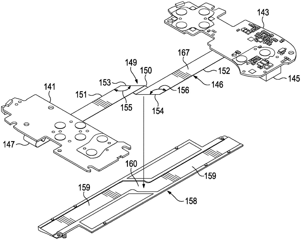
As illustrated inFIGS.19-21, the first handle101includes a first electronic circuit141that is coupled to the first hardware interface103. For example, as illustrated inFIGS.17and19, the first hardware interface103has a corresponding feature142of the first electronic circuit141. The corresponding feature142of the first electronic circuit141is configured to translate a mechanical, touch input the first hardware interface103into an electrical signal. Hence, for example, the corresponding feature142of the first electronic circuit141may be an electronic switch.
Likewise, the second handle102includes a second electronic circuit143that is coupled to the second hardware interface104. For example, as illustrated inFIGS.17and19, the second hardware interface104has a corresponding feature144of the second electronic circuit143. The corresponding feature144of the second electronic circuit143is configured to translate a mechanical, touch input the second hardware interface104into an electrical signal. Hence, for example, the corresponding feature144of the second electronic circuit143may be an electronic switch.
The second handle102further includes an electronic controller145. The electronic controller145is configured to receive an electrical signal from the second electronic circuit143. The electrical signal from the second electronic circuit143may be, for example, the electrical signal produced by the corresponding feature144of the second electronic circuit143in response to a touch input at the second hardware interface104. The electronic controller145is also configured to receive an electrical signal from the first electronic circuit141via a flat, flexible cable146. The electrical signal from the first electronic circuit141may be, for example, the electrical signal produced by the corresponding feature142of the first electronic circuit141in response to a touch input at the first hardware interface103.
The flat, flexible cable146is configured to conduct an electrical signal between the first handle and the second handle. In configurations, the flat, flexible cable146is a flat and flexible plastic film base, with multiple, flat, metallic conductors bonded to one surface of the film base. As illustrated most clearly inFIG.21, the flat, flexible cable146may be coupled at a first end147of the flat, flexible cable146to the first electronic circuit141and, at a second end148of the flat, flexible cable146, to the second electronic circuit143.
As illustrated most clearly inFIG.20, in configurations the flat, flexible cable146includes a double fold149. In configurations, the double fold149may be at the midline121of the bridge119. In the illustrated configuration, the double fold149includes a folded section150. Between the folded section150and a first elongated section151of the flat, flexible cable146is a first fold153. And between the folded section150and a second elongated section152of the flat, flexible cable146is a second fold154.
As illustrated, the fold angle155of the first fold153and the fold angle156of the second fold154are substantially equal and are less than 180°. As used in this context, “substantially equal” means largely or essentially equivalent, without requiring perfect identicalness. Accordingly, the first elongated section151of the flat, flexible cable146and the second elongated section152of the flat, flexible cable146are substantially parallel. As used in this context, “substantially parallel” means largely or essentially equidistant at all points (if the longitudinal centerline169of each elongated section were conceptually extended), without requiring perfect parallelism.
Consequently, the folded section150is at an angle to each of the first elongated section151and the second elongated section152as defined by the fold angles. Stated another way, before it is folded, the flat, flexible cable146has a longitudinal centerline169midway between its edges. Once folded, the longitudinal centerline169running through the first elongated section151and the longitudinal centerline169running through the folded section150are and an angle to each other, that angle being related to the fold angles.
In configurations, including in the illustrated configuration, the double fold149causes the same side157of the flat, flexible cable146to double over onto itself for each of the first fold153and the second fold154.
In configurations, the flat, flexible cable146is fixed to the bridge. The flat, flexible cable146may be fixed to the bridge by, for example, glue or another adhesive. In configurations, the flat, flexible cable146is fixed to the bridge at the midline of the bridge. Fixing the flat, flexible cable146to the bridge may help to prevent the flat, flexible cable146from sliding within the bridge119during normal use of the game controller100, where the game controller100may be repeatedly moved between the retracted configuration and the extended configuration. In configurations where the flat, flexible cable146is fixed to the bridge, the bridge may or may not include the tray158(as describe below), the flat, flexible cable146may or may not include the double fold149, and the tray158may or may not include the double jog160(described below).
As illustrated most clearly inFIG.20, the bridge119may include a tray158that is configured to contain the flat, flexible cable146within the tray158. As illustrated, the tray158may include a narrow conduit159that is slightly wider and taller than the flat, flexible cable146such that the flat, flexible cable146fits snugly within the tray158. The tray158is configured to prevent the flat, flexible cable146from bunching during normal use of the game controller100, where the game controller100may be repeatedly moved between the retracted configuration and the extended configuration.
In configurations, the tray158may include a double jog160, or turn. The double jog160in the tray158is configured to snugly contain the double fold149of the flat, flexible cable146. Accordingly, the double fold149of the flat, flexible cable146coincides with the double jog160in the tray158. The combination of the double fold149and the double jog160help to prevent the flat, flexible cable146from sliding within the tray158(and, therefore, within the bridge119) during normal use of the game controller100, where the game controller100may be repeatedly moved between the retracted configuration and the extended configuration.
FIG.22is a front view of the game controller ofFIG.17, in the example of the retracted configuration of the game controller, and showing only certain features internal to the game controller.FIG.23is a front view of the game controller ofFIG.18, in the example of the extended configuration of the game controller, and showing only certain features internal to the game controller.
As illustrated inFIGS.22and23, the flat, flexible cable146includes a first double loop161within the first handle101, and the flat, flexible cable146includes a second double loop162within the second handle102. As used in this context, a “double loop” means two loops, one following the other, the first of the two loops163having a center of curvature164that is on an opposite side of the flat, flexible cable146from the center of curvature166of the second of the two loops165. As illustrated, the center of curvature164of the first of the two loops163is on the first side157of the flat, flexible cable146, while the center of curvature166of the second of the two loops165is on a second side167of the flat, flexible cable146, which is opposite the first side157of the flat, flexible cable146.
The double loops encourage the flat, flexible cable146to bunch within the first handle101or the second handle102, or both (namely, at the location of the first double loop161or the second double loop162, or both) rather than elsewhere along the flat, flexible cable146when the game controller100is moved between the retracted configuration and the extended configuration. In configurations, the flat, flexible cable146may include the first double loop161but not the second double loop162, the second double loop162but not the first double loop161, neither the first double loop161nor the second double loop162, or both the first double loop161and the second double loop162.
In configurations, the flat, flexible cable146may include a crimped portion168. The crimped portion168may, for example, be between the first of the two loops163and the second of the two loops165. In such configurations, to crimped portion168encourages the flat, flexible cable146to bunch at the location of the crimped portion168rather than elsewhere along the flat, flexible cable146when the game controller100is moved between the retracted configuration and the extended configuration. As illustrated, the crimped portion168may be used in conjunction with the first double loop161or the second double loop162, or both.
EXAMPLES
Illustrative examples of the disclosed technologies are provided below. An embodiment of the technologies may include one or more, and any combination of, the examples described below.
Example 1 includes a game controller for a mobile device, the game controller comprising: a first handle configured to contact and support a mobile device, the first handle comprising a user-accessible, first hardware interface on a main body portion of the first handle and configured to accept touch inputs; a second handle configured to contact and support the mobile device, the second handle comprising a user-accessible, second hardware interface on a main body portion of the second handle and configured to accept touch inputs; a bridge coupling the first handle to the second handle, the bridge being in sliding engagement with the first handle and the second handle; and a flat, flexible cable configured to conduct an electrical signal between the first handle and the second handle.
Example 2 includes the game controller of Example 1, further comprising: a first electronic circuit within the first handle, the first electronic circuit coupled to the first hardware interface; a second electronic circuit within the second handle, the second electronic circuit coupled to the second hardware interface; and an electronic controller in the second handle, the electronic controller configured to receive an electrical signal from the second electronic circuit within the second handle and to receive an electrical signal from the first electronic circuit within the first handle via the flat, flexible cable.
Example 3 includes the game controller of any of Examples 1-2, the bridge further comprising a tray configured to contain the flat, flexible cable within the tray.
Example 4 includes the game controller of Example 3, in which the flat, flexible cable includes a double fold, the double fold coinciding with a double jog in the tray.
Example 5 includes the game controller of any of Examples 1-4, in which the bridge has a span extending away from the main body portion of the first handle, the span having a transverse midline, the midline of the bridge being between the first handle and the second handle, the bridge and the first handle being configured for the main body portion of the first handle to translate in a retraction direction toward the midline of the bridge and into a retracted configuration and also to translate in an extension direction away from the midline of the bridge into an extended configuration, the bridge and the second handle being configured for the main body portion of the second handle to translate along the bridge in the retraction direction toward the midline of the bridge and into the retracted configuration and also to translate in the extension direction away from the midline of the bridge and into the extended configuration.
Example 6 includes the game controller of Example 5, in which the flat, flexible cable includes a double fold at the midline of the bridge.
Example 7 includes the game controller of Example 6, the bridge further comprising a tray configured to contain the flat, flexible cable within the tray, the double fold of the flat, flexible cable coinciding with a double jog in the tray.
Example 8 includes the game controller of any of Examples 5-7, in which the flat, flexible cable is fixed to the bridge at the midline of the bridge.
Example 9 includes the game controller of any of Examples 1-8, in which the flat, flexible cable includes a double loop within the first handle.
Example 10 includes the game controller of Example 9, in which the flat, flexible cable further includes a crimped portion between a first loop of the double loops and a second loop of the double loop.
Example 11 includes the game controller of any of Examples 1-10, in which the flat, flexible cable includes a double loop within the second handle.
Example 12 includes the game controller of Example 11, in which the flat, flexible cable further includes a crimped portion between a first loop of the double loops and a second loop of the double loop.
Example 13 includes the game controller of any of Examples 1-12, further comprising: a first linear rack coupled to the first handle and in sliding engagement with the bridge, the first linear rack extending substantially along the span of the bridge; and a pinion affixed to the bridge and in contact with the first linear rack, the pinion configured to rotate relative to the bridge as the first linear rack is translated relative to the pinion.
Example 14 includes the game controller of Example 13, further comprising a second linear rack coupled to the second handle and in sliding engagement with the bridge, the second linear rack extending substantially along the span of the bridge, the pinion being in contact with the second linear rack, the pinion further configured to rotate relative to the bridge as the second linear rack is translated relative to the pinion.
Example 15 includes the game controller of any of Examples 1-14, in which a guide portion of the first handle extends from the main body portion of the first handle and along a first end of the span of the bridge, the guide portion of the first handle configured to align the bridge with the main body portion of the first handle.
Example 16 includes the game controller of Example 15, in which a guide portion of the second handle extends from the main body portion of the second handle and along a second end of the span of the bridge, the guide portion of the second handle configured to align the bridge with the main body portion of the second handle.
Example 17 includes the game controller of any of Examples 1-16, in which the flat, flexible cable includes a double fold within the bridge.
Example 18 includes the game controller of Example 17, in which the double fold comprises a first fold being between a first elongated section of the flat, flexible cable and a folded section of the flat, flexible cable and a second fold being between a second elongated section of the flat, flexible cable and the folded section.
Example 19 includes the game controller of Example 18, in which a fold angle of the first fold and a fold angle of the second fold are substantially equal and are less than 180 degrees.
The previously described versions of the disclosed subject matter have many advantages that were either described or would be apparent to a person of ordinary skill. Even so, all of these advantages or features are not required in all versions of the disclosed apparatus, systems, or methods. For example, not all contemplated embodiments will include the second handle. As another example, not all contemplated embodiments having the second handle will include the second latch mechanism or the second spring mechanism. As another example, not all contemplated embodiments will include the connector of the game controller if, for example, the mobile device and the game controller communicate wirelessly.
Additionally, this written description makes reference to particular features. It is to be understood that the disclosure in this specification includes all possible combinations of those particular features. For example, where a particular feature is disclosed in the context of a particular aspect or embodiment, that feature can also be used, to the extent possible, in the context of other aspects and embodiments.
Also, when reference is made in this application to a method having two or more defined steps or operations, the defined steps or operations can be carried out in any order or simultaneously, unless the context excludes those possibilities.
Furthermore, the term “comprises” and its grammatical equivalents are used in this application to mean that other components, features, steps, processes, operations, etc. are optionally present. For example, an article “comprising” or “which comprises” components A, B, and C can contain only components A, B, and C, or it can contain components A, B, and C along with one or more other components.
Although specific embodiments have been illustrated and described for purposes of illustration, it will be understood that various modifications may be made without departing from the spirit and scope of the disclosure. Accordingly, the invention should not be limited except as by the appended claims.
Claims
- A game controller for a mobile device, the game controller comprising: a first handle comprising: a first guide portion comprising a first main surface and a first support surface, wherein the first support surface is configured to contact and support a mobile device above the first main surface of the first guide portion;and a user-accessible, first hardware interface;a first electronic circuit within the first handle the first electronic circuit coupled to the first hardware interface;a second handle comprising: a second guide portion comprising a second main surface and a second support surface, wherein the second support surface is configured to contact and support the mobile device above the second main surface of the second guide portion;and a user-accessible, second hardware interface;a second electronic circuit within the second handle, the second electronic circuit coupled to the second hardware interface;a bridge coupling the first handle to the second handle, the bridge being in sliding engagement with the first handle and the second handle;a flat, flexible cable configured to conduct an electrical signal between the first handle and the second handle;and an electronic controller in the second handle, the electronic controller configured to receive an electrical signal from the second electronic circuit within the second handle and to receive an electrical signal from the first electronic circuit within the first handle via the flat, flexible cable.
- The game controller of claim 1, in which the flat, flexible cable includes a double loop within the first handle.
- The game controller of claim 2, in which the flat, flexible cable further includes a crimped portion between a first loop of the double loop and a second loop of the double loop.
- The game controller of claim 1, in which the flat, flexible cable includes a double fold within the bridge.
- The game controller of claim 4, in which the double fold comprises a first fold being between a first elongated section of the flat, flexible cable and a folded section of the flat, flexible cable and a second fold being between a second elongated section of the flat, flexible cable and the folded section.
- The game controller of claim 5, in which a fold angle of the first fold and a fold angle of the second fold are substantially equal and are less than 180 degrees.
- The game controller of claim 1, further comprising a wired connector configured for physical and electrical connection with a corresponding port on the mobile phone.
- The game controller of claim 7, wherein the wired connector comprises a USB-C connector.
- A game controller for a mobile device, the game controller comprising: a first handle configured to contact and support a mobile device, the first handle comprising a user-accessible, first hardware interface;a second handle configured to contact and support the mobile device, the second handle comprising a user-accessible, second hardware interface;a bridge coupling the first handle to the second handle, the bridge being in sliding engagement with the first handle and the second handle;and a flat, flexible cable configured to conduct an electrical signal between the first handle and the second handle;wherein the bridge further comprises a tray configured to contain the flat, flexible cable within the tray;and wherein the flat, flexible cable is prevented from sliding in the tray as the first and second handles move between retracted and extended positions.
- The game controller of claim 9, in which the flat, flexible cable includes a double fold, the double fold coinciding with a double jog in the tray.
- The game controller of claim 9, wherein the flat, flexible cable is prevented from sliding in the tray because of a physical feature of the tray.
- The game controller of claim 11, wherein the physical feature comprises a recess in the tray that is shaped as an outline of the flat, flexible cable.
- The game controller of claim 11, wherein the physical feature comprises a double jog.
- The game controller of claim 9, wherein the flat, flexible cable is fixed to the tray.
- The game controller of claim 14, wherein the flat, flexible cable is fixed to the tray with an adhesive.
- The game controller of claim 9, wherein: the first handle comprises a first guide portion comprising a first main surface and a first support surface, wherein the first support surface is configured to contact and support the mobile device above the first main surface of the first guide portion;and the second handle comprising a second guide portion comprising a second main surface and a second support surface, wherein the second support surface is configured to contact and support the mobile device above the second main surface of the second guide portion.
- The game controller of claim 9, wherein the flat, flexible cable is allowed to bunch in the first handle and/or second handle rather than elsewhere along the flat, flexible cable when the first and second handles move between retracted and extended positions.
- The game controller of claim 17, wherein the flat, flexible cable is allowed to bunch due to a double loop in the flat, flexible cable.
- The game controller of claim 17, wherein the flat, flexible cable is allowed to bunch due to a crimped portion in the flat, flexible cable.
- A game controller for a mobile device, the game controller comprising: a first handle configured to contact and support a mobile device, the first handle comprising a user-accessible, first hardware interface;a second handle configured to contact and support the mobile device, the second handle comprising a user-accessible, second hardware interface;a bridge coupling the first handle to the second handle, the bridge being in sliding engagement with the first handle and the second handle;a flat, flexible cable configured to conduct an electrical signal between the first handle and the second handle;and a pinion affixed to the bridge, wherein rotation of the pinion caused by linear movement of one of the first and second handles causes linear movement of the other of the first and second handles.
- The game controller of claim 20, in which the bridge has a span extending away from a main body portion of the first handle, the span having a transverse midline, the midline of the bridge being between the first handle and the second handle, the bridge and the first handle being configured for the main body portion of the first handle to translate in a retraction direction toward the midline of the bridge and into a retracted configuration and also to translate in an extension direction away from the midline of the bridge into an extended configuration, the bridge and the second handle being configured for a main body portion of the second handle to translate along the bridge in the retraction direction toward the midline of the bridge and into the retracted configuration and also to translate in the extension direction away from the midline of the bridge and into the extended configuration.
- The game controller of claim 21, in which the flat, flexible cable includes a double fold at the midline of the bridge.
- The game controller of claim 22, the bridge further comprising a tray configured to contain the flat, flexible cable within the tray, the double fold of the flat, flexible cable coinciding with a double jog in the tray.
- The game controller of claim 21, in which the flat, flexible cable is fixed to the bridge at the midline of the bridge.
- The game controller of claim 20, wherein: the first handle comprises a first guide portion comprising a first main surface and a first support surface, wherein the first support surface is configured to contact and support the mobile device above the first main surface of the first guide portion;and the second handle comprising a second guide portion comprising a second main surface and a second support surface, wherein the second support surface is configured to contact and support the mobile device above the second main surface of the second guide portion.
Disclaimer: Data collected from the USPTO and may be malformed, incomplete, and/or otherwise inaccurate.