U.S. Pat. No. 12,121,800
HAPTICS FOR TOUCH-INPUT HARDWARE INTERFACES OF A GAME CONTROLLER
AssigneeBackbone Labs, Inc.
Issue DateJuly 20, 2023
Illustrative Figure
Abstract
A handheld game controller having a handle and a bumper assembly on the handle. The bumper assembly includes a bumper and a haptic actuator. The bumper is configured to accept touch inputs from a user. The haptic actuator includes at least one plate and a piezoelectric actuator. The piezoelectric actuator is configured to receive an electrical signal, convert the electrical signal to mechanical motion, translate the mechanical motion to the at least one plate, and cause the at least one plate and the bumper to vibrate.
Description
DETAILED DESCRIPTION As described herein, aspects are directed to an apparatus and method for providing haptic feedback in a handheld game controller. In configurations, a handheld game controller includes a haptic actuator as part of the assembly for a touch-input hardware interface. The touch-input hardware interface may be, for example, a bumper or trigger, and other examples are noted below. The haptic actuator includes a piezoelectric actuator that provides haptic feedback to the user through the touch-input hardware interface (e.g., the bumper or trigger). Additionally, configurations include capacitive touch sensor to engage and disengage the piezoelectric actuator in response to the user's touch. Also, in configurations having more than one piezoelectric actuator on a given touch-input hardware interface (e.g., a bumper or trigger), the separate piezoelectric actuators may be engaged simultaneously or at separate times (and perhaps in a certain sequence) to provide different types of haptic feedback to the user's finger. In addition to the benefits just noted, configurations of the disclosed technology help to differentiate haptics coming from a haptic engine in the mobile device from the haptics generated from within the game controller. This is accomplished by, for example, focusing the haptic feedback on a particular part of the game controller, such as a particular bumper or trigger. FIG.1is a perspective view showing portions of a handheld game controller, according to an example configuration.FIG.2is a top perspective view of the game controller ofFIG.1. As illustrated inFIGS.1and2, a game controller100may include a first handle101, a second handle102, and a bridge119. Each of the first handle101and the second handle102is configured to contact and support a mobile device199, though not all contemplated embodiments will include the second handle102. An exemplary mobile device199is shown in broken lines to illustrate how the game controller100may contact and support a mobile device199in some embodiments. ...
DETAILED DESCRIPTION
As described herein, aspects are directed to an apparatus and method for providing haptic feedback in a handheld game controller. In configurations, a handheld game controller includes a haptic actuator as part of the assembly for a touch-input hardware interface. The touch-input hardware interface may be, for example, a bumper or trigger, and other examples are noted below. The haptic actuator includes a piezoelectric actuator that provides haptic feedback to the user through the touch-input hardware interface (e.g., the bumper or trigger). Additionally, configurations include capacitive touch sensor to engage and disengage the piezoelectric actuator in response to the user's touch. Also, in configurations having more than one piezoelectric actuator on a given touch-input hardware interface (e.g., a bumper or trigger), the separate piezoelectric actuators may be engaged simultaneously or at separate times (and perhaps in a certain sequence) to provide different types of haptic feedback to the user's finger. In addition to the benefits just noted, configurations of the disclosed technology help to differentiate haptics coming from a haptic engine in the mobile device from the haptics generated from within the game controller. This is accomplished by, for example, focusing the haptic feedback on a particular part of the game controller, such as a particular bumper or trigger.
FIG.1is a perspective view showing portions of a handheld game controller, according to an example configuration.FIG.2is a top perspective view of the game controller ofFIG.1.
As illustrated inFIGS.1and2, a game controller100may include a first handle101, a second handle102, and a bridge119. Each of the first handle101and the second handle102is configured to contact and support a mobile device199, though not all contemplated embodiments will include the second handle102. An exemplary mobile device199is shown in broken lines to illustrate how the game controller100may contact and support a mobile device199in some embodiments. The mobile device199may be, as examples, a smartphone or a tablet computer.
As illustrated inFIGS.1and2, the first handle101includes a guide portion113and a main body portion105. The guide portion113extends from the main body portion105and along a first end115of the span120of the bridge119. The guide portion113of the first handle101is configured to align the bridge119with the main body portion105of the first handle101.
As illustrated, the first handle101includes a user-accessible, first hardware interface103on the main body portion105of the first handle101. The first hardware interface103could be a button, a bumper, a trigger, an analog stick, a touchscreen, a touchpad, a knob, a slider, a switch, a wheel, a dial, a directional pad, or another such feature configured to accept touch inputs from a user's finger or a stylus. As shown inFIGS.1and2, the first hardware interface103may include multiple such hardware interfaces.
As best illustrated inFIG.2, the user-accessible, first hardware interface103may include a first touch-input hardware interface129coupled to the first handle101. The first touch-input hardware interface129is configured to accept touch inputs from a user. For example, the user might depress the first touch-input hardware interface129with the user's index finger or middle finger. As illustrated, the first touch-input hardware interface129may be at a top edge131of the main body portion105of the first handle101. The main body portion105is confined by a housing132of the first handle101. As illustrated in the drawings, in configurations the first touch-input hardware interface129projects from the housing132of the first handle101. The first touch-input hardware interface129may be, for example, a bumper or trigger, or it may be one of the other features noted above for the first hardware interface103that are configured to accept touch inputs from a user's finger or a stylus. Typically, though, the first touch-input hardware interface129is a mechanical input device, such as a button, a bumper, a trigger, an analog stick, a knob, a slider, a switch, a wheel, a dial, or a directional pad.
Referring toFIGS.1and2together, the second handle102likewise includes a guide portion114and a main body portion106. The guide portion114extends from the main body portion106and along a second end116of the span120of the bridge119. The guide portion114of the second handle102is configured to align the bridge119with the main body portion106of the second handle102.
As illustrated, the second handle102further includes a user-accessible, second hardware interface104on the main body portion106of the second handle102. As above for the first hardware interface103of the first handle101, the second hardware interface104could be a button, a bumper, a trigger, an analog stick, a touchscreen, a touchpad, a knob, a slider, a switch, a wheel, a dial, a directional pad, or another such feature configured to accept touch inputs from a user's finger or a stylus. The second hardware interface104may include multiple such hardware interfaces, as illustrated inFIGS.1and2.
As best illustrated inFIG.2, the user-accessible, second hardware interface104may include a second touch-input hardware interface154coupled to the second handle102. The second touch-input hardware interface154is configured to accept touch inputs from a user as described above for the first touch-input hardware interface129. As illustrated, the second touch-input hardware interface154may be at a top edge of the main body portion106of the second handle102. The main body portion106is confined by a housing133of the second handle102. As illustrated in the drawings, in configurations the second touch-input hardware interface154projects from the housing133of the second handle102. The second touch-input hardware interface154may be, for example, a bumper or trigger, or it may be one of the other features noted above for the second hardware interface104that are configured to accept touch inputs from a user's finger or a stylus. Typically, though, the second touch-input hardware interface154is a mechanical input device, such as a button, a bumper, a trigger, an analog stick, a knob, a slider, a switch, a wheel, a dial, or a directional pad.
One or both of the first handle101and the second handle102may include a connector125for physical and electrical connection to the mobile device199. The connector125may be, for example, a USB-C connector.
It is noted that each ofFIGS.1,3,4, and5includes indications showing the directions of mutually orthogonal x-, y-, and z-axes. These are used to orient the reader and to assist with the descriptions of the illustrated configurations. Accordingly, the bridge119lies in the x-y plane as illustrated, and the intended gameplay position of the mobile device199is substantially parallel to the x-y plane of the bridge119, such as is illustrated inFIGS.1and3-5. As used in this context, “substantially parallel” means largely or essentially equidistant from the x-y plane at all points, without requiring perfect parallelism.
FIG.3is a front view of the handheld game controller ofFIG.1.FIG.4is a top view of the handheld game controller ofFIG.1, shown in an example extended position. AndFIG.5is a top view of the handheld game controller ofFIG.1, shown in an example retracted position.FIGS.3-5illustrate an example of how a mobile device199may be installed into the game controller100. As illustrated inFIG.4, the mobile device199may be placed over the bridge119, between the first handle101and the second handle102of the game controller100. The connector125of the game controller100may be joined with a corresponding connector on the mobile device199.FIG.4shows an example of an extended configuration of the game controller100, where the handles are extended away from each other a sufficient distance to allow the mobile device199to be inserted. InFIG.5, the mobile device199is secured between the first handle101and the second handle102of the game controller100.FIGS.3and5illustrate an example of a retracted configuration of the game controller100, where the handles are retracted toward each other such that the mobile device199contacts the contact zone (explained below). The extended configuration and the retracted configuration of the game controller100are described in more detail below.
Hence, as illustrated the bridge119is in sliding engagement with the first handle101. In the illustrated configuration, the bridge119is not telescoping, meaning that segments of the bridge119do not slide within another segment of the bridge119to allow for lengthening or shortening of the bridge119. The bridge119has a span120extending away from the main body portion105of the first handle101, and the span120has a transverse midline121.
The bridge119and the first handle101are configured to allow the main body portion105of the first handle101to translate in a retraction direction122toward the midline121of the bridge119and into a retracted configuration, an example of which is illustrated inFIGS.3and5. The bridge119and the first handle101are configured to allow the main body portion105of the first handle101to also translate in an extension direction123away from the midline121of the bridge119into an extended configuration, an example of which is illustrated inFIG.4.
As used in this disclosure, the transverse midline121of the bridge119is a reference datum used to define the extension direction123and the retraction direction122. That is, the retraction direction122is toward the transverse midline121, while the retraction direction122is away from the transverse midline121. Accordingly, the transverse midline121of the bridge119may or may not coincide with a physical structure on the game controller100.
Likewise, the bridge119, as illustrated, is in sliding engagement with the second handle102, and the span120of the bridge119extends away from the main body portion106of the second handle102. The bridge119and the second handle102are configured to allow the main body portion106of the second handle102to translate in the retraction direction122toward the midline121of the bridge119and into the retracted configuration. The bridge119and the second handle102are configured to allow the main body portion106of the second handle102to also translate in the extension direction123away from the midline121of the bridge119into the extended configuration.
In configurations, the bridge119is configured such that the first handle101and the second handle102are equidistant from the midline121of the bridge119in the retracted configuration and in the extended configuration. In configurations, the bridge119is configured such that the first handle101and the second handle102are equidistant from the midline121of the bridge119when the first handle101and the second handle102are translating from the retracted configuration to the extended configuration. In configurations, the bridge119is configured such that the first handle101and the second handle102are equidistant from the midline121of the bridge119when the first handle101and the second handle102are translating from the extended configuration to the retracted configuration.
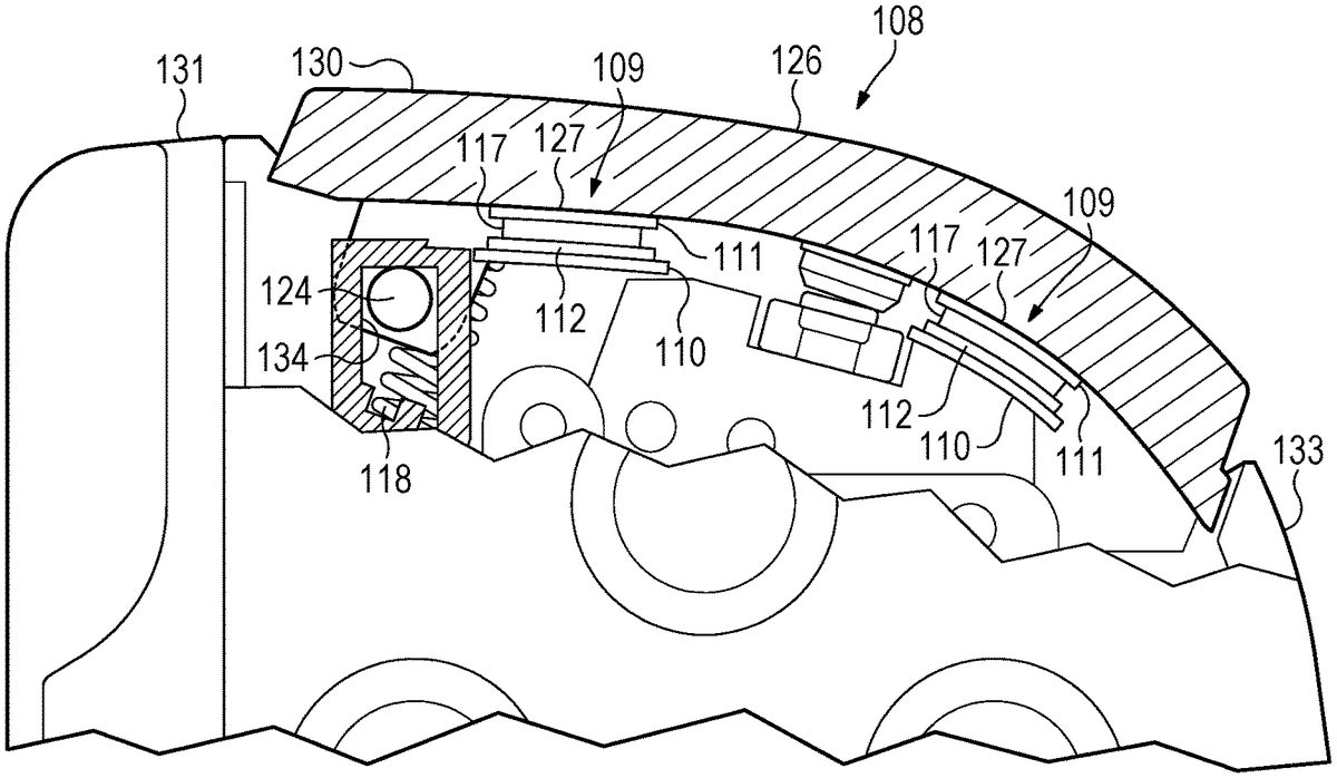
FIG.6is a partial sectional view of a portion of the second handle102ofFIG.1, illustrating an example haptic actuator109embedded in the second touch-input hardware interface130.FIG.7is a partial sectional view of a portion of the second handle102ofFIG.1, illustrating an example haptic actuator109in direct, physical contact with the second touch-input hardware interface130. While illustrated and described for the second handle102, the discussion ofFIGS.6and7applies also to the first handle101. Indeed, the game controller100may include a touch-input assembly on one or both handles, namely the first touch-input assembly107, which includes the first touch-input hardware interface129, and the second touch-input assembly108, which includes the second touch-input hardware interface130.
As illustrated inFIGS.6and7, the second touch-input assembly108includes a second touch-input hardware interface130and a haptic actuator109.
The touch-input hardware interface is configured to accept touch inputs from a user. In configurations, the touch-input hardware interface may be, for example, a button, a bumper, a trigger, an analog stick, a knob, a slider, a switch, a wheel, a dial, or a directional pad. In the illustrated configuration, the touch-input hardware interface is a bumper or trigger that the user might depress, typically with the user's index finger or middle finger.
As illustrated, the haptic actuator109includes a first plate111, a second plate112, and a piezoelectric actuator117. While the illustrated configuration shows two plates, the first plate111and the second plate112, some configurations have just one plate and some configurations have more than two plates. As illustrated, the first plate111, the second plate112, and the piezoelectric actuator117are in layers, with the piezoelectric actuator117being between the first plate111and the second plate112.
The piezoelectric actuator117, or piezoelectric transducer, is configured to receive an electrical signal, convert the electrical signal to mechanical motion, translate the mechanical motion to the first plate111and the second plate112, and cause the first plate111and the second plate112to vibrate. The electrical signal to the piezoelectric actuator117may come from, as examples, a processor within the game controller100or a processor within the mobile device199. The processor within the game controller100may be, for example, part of a printed circuit board within the second handle102. Vibration of the plates, in turn, causes the second touch-input hardware interface130to vibrate. Accordingly, the haptic actuator109causes haptic vibration without the use of an eccentric rotating mass (ERM) or a linear resonant actuator (LRA). ERM- and LRA-type haptic actuators109are too bulky for the application described here and would not allow the second touch-input assembly108(which includes the haptic actuator109) to translate as a unit relative to the second handle or to focus the haptic feedback sensation (i.e. the vibrations) to a specific portion of the game controller100, such as to the second touch-input assembly108. In addition, ERM- and LRA-type haptic actuators109require more electrical power than the technologies discussed in this disclosure. Thus, the described technologies require less battery power, resulting in longer battery life, less frequent recharging of the battery, and less need to be tethered by a cord to an electrical outlet to provide power to depleted batteries.
In some example configurations, the layers of the haptic actuator109include a capacitive touch sensor128, such as a capacitive touch film. The capacitive touch sensor128is configured to detect presence of a finger of the user on the second touch-input hardware interface130. Such capacitive touch sensors128typically have a grid of electrodes that complete an electrical circuit in response to a user's touch. Accordingly, in configurations the haptic actuator109is “off” unless the capacitive touch sensor128detects a user's finger on the second touch-input hardware interface130. If a user's finger is detected, then the haptic actuator109is “on” and will cause the plate(s) to vibrate in response to an electrical signal as described above. In such configurations, battery power may be conserved by not activating the haptic feedback when the user's finger is not in place on the corresponding touch-input hardware interface. As illustrated inFIG.6, the capacitive touch sensor128may be affixed to the outward surface of the second touch-input hardware interface130. The outward surface is the surface indicated as including the contact surface area126and coincides with the input surface (which is described below) of the second touch-input hardware interface130. In some example configurations, the layers of the haptic actuator109do not include a capacitive touch sensor128.
In configurations, the layers of the haptic actuator109include a flexible, printed circuit board110. In configurations, the flexible circuit board110is connected via a flexible cable to the main circuit board of the game controller100. As noted above, that main printed circuit board may be within the second handle102, or it may be elsewhere within the game controller100.
As illustrated inFIGS.6and7, the second touch-input hardware interface130and the haptic actuator109translate as a unit relative to the handle. To accomplish that, the second touch-input assembly108is not rigidly coupled to the housing133of the second handle102. Rather, the second touch-input assembly108is connected to the housing133through a non-rigid connection, such as through a pivot rod124and a spring118as illustrated inFIGS.6and7. As used in this context, a rigid coupling would not allow the coupled components to be moved relative to each other without causing permanent damage to either component. Accordingly, in such configurations the second touch-input assembly108is isolated from the main body portion106of the second handle106(because of the lack of a rigid coupling between them) and, likewise, from the remainder of the game controller100.
As illustrated, a track slot134is rigidly coupled to the housing133, and the second touch-input hardware interface130includes a pivot rod124. The pivot rod124is configured to engage the track slot134of the second handle102. The pivot rod124is configured to rotate within the track slot134and to translate within the track slot134. Accordingly, the pivot rod124and track slot134provide a dual-action coupling between the second touch-input assembly108and the housing133of the second handle102, the two actions being rotation and translation. The spring118is configured to bias the second touch-input hardware interface130into the upward, or undepressed, position, an example of which is shown inFIGS.6and7. Hence, in configurations where the haptic actuator109translates as a unit relative to the handle and the touch-input assembly is connected to the housing133through a non-rigid connection, the haptic feedback provided by the haptic actuator109may be focused on a particular part of the game controller (namely the second touch-input hardware interface130to which the particular haptic actuator109is coupled) rather than the game controller as a whole.
As noted above,FIG.6illustrates a haptic actuator109that is embedded in the second touch-input hardware interface130. As used in this context, “embedded” means that the haptic actuator109is snugly enclosed in the second touch-input hardware interface130, which substantially surrounds the haptic actuator109. As used in this context, “substantially surrounds” means largely or essentially extending around, without requiring perfect encircling. By contrast,FIG.7illustrates a haptic actuator109that, instead of being embedded in the second touch-input hardware interface130, is in direct, physical contact with the second touch-input hardware interface130. In the example configuration ofFIG.7, then, the haptic actuator109is coupled to an underside of the second touch-input hardware interface130. In other configurations, the haptic actuator109could be coupled to another part of the second touch-input assembly108. These two configurations (i.e. embedded within the second touch-input hardware interface130or being in direct, physical contact with the second touch-input hardware interface130) each provide non-dampened, no-gap contact between the haptic actuator109and the second touch-input hardware interface130, which transfers the mechanical force (i.e. the vibration) of the haptic actuator109to the input surface (i.e. where the user places their finger during typical use) of the second touch-input hardware interface130.
As best illustrated inFIGS.2,6, and7, the second touch-input hardware interface130has a contact surface area126of an outward surface of the second touch-input hardware interface130. The outward surface of the second touch-input hardware interface130is configured to receive touch inputs from the user and coincides with the input surface of the second touch-input hardware interface130. The haptic actuator109has a planform area127in the y-axis. For the illustrated configuration, this planform area127is indicated by the dashed-line circles109inFIG.2. (The planform area127is shown from the side inFIGS.6and7.) In configurations, the planform area127of the haptic actuator109is less than the contact surface area126of the outward surface of the second touch-input hardware interface130.
In configurations, a single touch-input hardware interface may include more than one haptic actuator109. The haptic actuators109may be spaced apart to provide haptic feedback (i.e. vibrations) to different parts of the input surface. WhileFIG.2shows an example of the touch-input hardware interfaces each having two haptic actuators109, other configurations could have more than two haptic actuators109. For example a single touch-input hardware interface may include four haptic actuators109arranged at the corners of a rectangular shape. In configurations having more than one haptic actuator109on a single touch-input hardware interface, the haptic actuators109can be activated and deactivated individually. Accordingly, the haptic actuators109can be turned “on” and “off” separately (including in a particular sequence). Thus, while conventional systems either have the haptics on or off, configurations of the disclosed technology provide a range of haptic feedback by engaging one haptic actuator109on a touch-input hardware interface (e.g. a bumper or trigger), multiple haptic actuators109on the same touch-input hardware interface simultaneously, or multiple haptic actuators109on the same touch-input hardware interface individually (including sequentially). Engaging the haptic actuators109sequentially may provide, for example, a sense of movement to the user. Additionally, engaging more than one of the haptic actuators109at the same time may provide, for example, a sense of stronger force to the user as compared to when fewer haptic actuators109are engaged.
Although described with respect to the illustrated bumper, it is recognized that the disclosed haptics technology could be applied to other types of user-accessible, touch-input hardware interfaces such as, for example, a button, an analog stick, a touchscreen, a touchpad, a knob, a slider, a switch, a wheel, a dial, a directional pad, and a trigger.
In use, the user holds the game controller in the customary way. That typically means holding each handle with the user's thumbs available to activate the hardware interfaces103,104(e.g., buttons, joysticks, etc.) on the front side of the handles101,102. The user's index or middle finger is typically available to activate the touch-input hardware interfaces129,130(e.g. the bumpers, triggers, etc.) at the top edge131of the handle101,102. With the user's finger(s) resting on the touch-input hardware interface(s), in configurations having the capacitive touch sensor128, the capacitive touch sensor128would detect the presence of the user's finger and send a signal, either directly to the corresponding haptic actuator109or to another processor, to turn the haptic actuator109“on” so that it will vibrate in response to a received electrical signal indicative of when haptic feedback should occur during gameplay. As noted, each touch-input hardware interface may have more than one haptic actuator109. In such configurations, the haptic actuators109can be controlled separately to provide haptic feedback to the user that is more complex and immersive than (a) the haptics provided by the mobile device itself, (b) a single haptic engine rigidly coupled to the housing of the game controller, or (c) a single haptic actuator109for the particular touch-input hardware interface.
EXAMPLES
Illustrative examples of the disclosed technologies are provided below. A particular configuration of the technologies may include one or more, and any combination of, the examples described below.
Example 1 includes a handheld game controller comprising: a handle; and a bumper assembly on the handle, the bumper assembly comprising: a bumper configured to accept touch inputs from a user, and a haptic actuator comprising at least one plate and a piezoelectric actuator configured to receive an electrical signal, convert the electrical signal to mechanical motion, translate the mechanical motion to the at least one plate, and cause the at least one plate and the bumper to vibrate.
Example 2 includes the handheld game controller of Example 1, in which the bumper assembly is configured to translate as a unit relative to the handle.
Example 3 includes the handheld game controller of any of Examples 1-2, in which the handle further comprises a housing from which the bumper projects, and in which the bumper assembly is not rigidly coupled to the housing.
Example 4 includes the handheld game controller of Example 3, in which the bumper assembly is connected to the housing through at least one spring and at least one pivot.
Example 5 includes the handheld game controller of any of Examples 1-4, in which the bumper has a contact surface area of an outward surface of the bumper, the outward surface of the bumper being configured to receive touch inputs from the user, the haptic actuator having a planform area, the planform area of the haptic actuator being less than the contact surface area of the outward surface of the bumper.
Example 6 includes the handheld game controller of any of Examples 1-5, in which the haptic actuator further includes a capacitive touch sensor configured to detect presence of a finger of the user on the bumper.
Example 7 includes the handheld game controller of any of Examples 1-6, in which the haptic actuator does not include an eccentric rotating mass or a linear resonant actuator to cause vibration.
Example 8 includes the handheld game controller of any of Examples 1-7, in which the haptic actuator comprises layers, the layers including a first plate; a second plate; and the piezoelectric actuator; the piezoelectric actuator being between the first plate and the second plate, the piezoelectric actuator configured to receive the electrical signal and mechanically vibrate the first plate and the second plate in response to the electrical signal.
Example 9 includes the handheld game controller of Example 8, the layers of the haptic actuator further including a capacitive touch sensor configured to detect presence of a finger of the user on the bumper.
Example 10 includes the handheld game controller of any of Examples 1-9, in which the haptic actuator is in direct, physical contact with the bumper.
Example 11 includes the handheld game controller of any of Examples 1-10, in which the haptic actuator is embedded in the bumper.
Example 12 includes the handheld game controller of any of Examples 1-11, in which the handle is a first handle, the handheld game controller further comprising: a second handle; a bridge connecting the first handle and the second handle; a second bumper assembly on the second handle, the second bumper assembly comprising: a second bumper configured to accept touch inputs from the user, and a second haptic actuator comprising at least one plate and a piezoelectric actuator configured to receive an electrical signal, convert the electrical signal to mechanical motion, translate the mechanical motion to the at least one plate of the second haptic actuator, and cause the at least one plate of the second haptic actuator and the second bumper to vibrate.
Example 13 includes the handheld game controller of Example 12, in which the bridge is in sliding engagement with the first handle and the second handle, the bridge having a span extending away from the first handle, the span having a transverse midline, the midline of the bridge being between the first handle and the second handle, the bridge and the first handle being configured for the first handle to translate in a retraction direction toward the midline of the bridge and into a retracted configuration and also to translate in an extension direction away from the midline of the bridge into an extended configuration, the bridge and the second handle being configured for the second handle to translate along the bridge in the retraction direction toward the midline of the bridge and into the retracted configuration and also to translate in the extension direction away from the midline of the bridge and into the extended configuration.
Example 14 includes the handheld game controller of any of Examples 1-13, further comprising a mobile device contacted and supported by the first handle and the second handle.
Example 15 includes the handheld game controller of any of Examples 1-14, in which the haptic actuator is a plurality of haptic actuators, each haptic actuator of the plurality of haptic actuators comprising at least one plate and a piezoelectric actuator configured to receive an electrical signal, convert the electrical signal to mechanical motion, translate the mechanical motion to the at least one plate, and cause the at least one plate and the bumper to vibrate, each haptic actuator of the plurality of haptic actuators being separably controllable to turn off and on independently of another haptic actuator of the plurality of haptic actuators.
Example 16 includes a handheld game controller comprising: a handle; and a touch-input assembly on the handle, the touch-input assembly comprising: a touch-input hardware interface configured to accept touch inputs from a user, and a haptic actuator comprising at least one plate and a piezoelectric actuator configured to receive an electrical signal, convert the electrical signal to mechanical motion, translate the mechanical motion to the at least one plate, and cause the at least one plate to vibrate.
Example 17 includes the handheld game controller of Example 16, in which the touch-input assembly is configured to translate as a unit relative to the handle.
Example 18 includes the handheld game controller of any of Examples 16-17, in which the handle further comprises a housing from which the touch-input hardware interface projects, and in which the touch-input assembly is not rigidly coupled to the housing.
Example 19 includes the handheld game controller of any of Examples 16-18, in which the haptic actuator does not include an eccentric rotating mass or a linear resonant actuator to cause vibration.
Example 20 includes the handheld game controller of any of Examples 16-19, in which the haptic actuator comprises layers, the layers including: a first plate; a second plate; and a piezoelectric transducer between the first plate and the second plate, the piezoelectric transducer configured to receive an electrical signal and mechanically vibrate the first plate and the second plate in response to the electrical signal.
Example 21 includes the handheld game controller of Example 20, the layers of the haptic actuator further including a capacitive touch sensor configured to detect presence of a finger of the user on the touch-input hardware interface.
Example 22 includes the handheld game controller of any of Examples 16-21, in which the touch-input hardware interface is selected from the group consisting of a button, an analog stick, a knob, a slider, a switch, a wheel, a dial, a directional pad, and a trigger.
Aspects may operate on a particularly created hardware, on firmware, digital signal processors, or on a specially programmed general purpose computer including a processor operating according to programmed instructions. The terms “controller” or “processor” as used herein are intended to include microprocessors, microcomputers, ASICs, and dedicated hardware controllers. One or more aspects may be embodied in computer-usable data and computer-executable instructions, such as in one or more program modules, executed by one or more computers (including monitoring modules), or other devices. Generally, program modules include routines, programs, objects, components, data structures, etc. that perform particular tasks or implement particular abstract data types when executed by a processor in a computer or other device. The computer executable instructions may be stored on a non-transitory computer readable medium such as a hard disk, optical disk, removable storage media, solid state memory, RAM, etc. As will be appreciated by one of skill in the art, the functionality of the program modules may be combined or distributed as desired in various configurations. In addition, the functionality may be embodied in whole or in part in firmware or hardware equivalents such as integrated circuits, field programmable gate arrays (FPGA), and the like. Particular data structures may be used to more effectively implement one or more aspects of the disclosed systems and methods, and such data structures are contemplated within the scope of computer executable instructions and computer-usable data described herein.
The previously described versions of the disclosed subject matter have many advantages that were either described or would be apparent to a person of ordinary skill. Even so, all of these advantages or features are not required in all versions of the disclosed apparatus, systems, or methods.
Additionally, this written description makes reference to particular features. It is to be understood that the disclosure in this specification includes all possible combinations of those particular features. For example, where a particular feature is disclosed in the context of a particular example configuration, that feature can also be used, to the extent possible, in the context of other example configurations.
Also, when reference is made in this application to a method having two or more defined steps or operations, the defined steps or operations can be carried out in any order or simultaneously, unless the context excludes those possibilities.
Furthermore, the term “comprises” and its grammatical equivalents are used in this application to mean that other components, features, steps, processes, operations, etc. are optionally present. For example, an article “comprising” or “which comprises” components A, B, and C can contain only components A, B, and C, or it can contain components A, B, and C along with one or more other components.
Also, directions such as “vertical,” “horizontal,” “right,” and “left” are used for convenience and in reference to the views provided in figures. But the game controller may have a number of orientations in actual use. Thus, a feature that is vertical, horizontal, to the right, or to the left in the figures may not have that same orientation or direction in actual use.
Although specific example configurations have been described for purposes of illustration, it will be understood that various modifications may be made without departing from the spirit and scope of the disclosure.
Claims
- A handheld game controller comprising: a handle;and a bumper assembly on the handle, the bumper assembly comprising: a bumper configured to accept touch inputs from a user, and a haptic actuator comprising at least one plate and a piezoelectric actuator configured to receive an electrical signal, convert the electrical signal to mechanical motion, translate the mechanical motion to the at least one plate, and cause the at least one plate and the bumper to vibrate;wherein the haptic actuator comprises layers, the layers including a first plate;a second plate;and the piezoelectric actuator;the piezoelectric actuator being between the first plate and the second plate, the piezoelectric actuator configured to receive the electrical signal and mechanically vibrate the first plate and the second plate in response to the electrical signal.
- The handheld game controller of claim 1, in which the bumper assembly is configured to translate as a unit relative to the handle.
- The handheld game controller of claim 1, in which the handle further comprises a housing from which the bumper projects, and in which the bumper assembly is not rigidly coupled to the housing.
- The handheld game controller of claim 3, in which the bumper assembly is connected to the housing through at least one spring and at least one pivot.
- The handheld game controller of claim 1, in which the bumper has a contact surface area of an outward surface of the bumper, the outward surface of the bumper being configured to receive touch inputs from the user, the haptic actuator having a planform area, the planform area of the haptic actuator being less than the contact surface area of the outward surface of the bumper.
- The handheld game controller of claim 1, in which the haptic actuator further includes a capacitive touch sensor configured to detect presence of a finger of the user on the bumper.
- The handheld game controller of claim 1, in which the haptic actuator does not include an eccentric rotating mass or a linear resonant actuator to cause vibration.
- The handheld game controller of claim 1, the layers of the haptic actuator further including a capacitive touch sensor configured to detect presence of a finger of the user on the bumper.
- The handheld game controller of claim 1, in which the haptic actuator is in direct, physical contact with the bumper.
- The handheld game controller of claim 1, in which the haptic actuator is embedded in the bumper.
- The handheld game controller of claim 1, in which the handle is a first handle, the handheld game controller further comprising: a second handle;a bridge connecting the first handle and the second handle;a second bumper assembly on the second handle, the second bumper assembly comprising: a second bumper configured to accept touch inputs from the user, and a second haptic actuator comprising at least one plate and a piezoelectric actuator configured to receive an electrical signal, convert the electrical signal to mechanical motion, translate the mechanical motion to the at least one plate of the second haptic actuator, and cause the at least one plate of the second haptic actuator and the second bumper to vibrate.
- The handheld game controller of claim 11, in which the bridge is in sliding engagement with the first handle and the second handle, the bridge having a span extending away from the first handle, the span having a transverse midline, the mid line of the bridge being between the first handle and the second handle, the bridge and the first handle being configured for the first handle to translate in a retraction direction toward the midline of the bridge and into a retracted configuration and also to translate in an extension direction away from the mid line of the bridge into an extended configuration, the bridge and the second handle being configured for the second handle to translate along the bridge in the retraction direction toward the mid line of the bridge and into the retracted configuration and also to translate in the extension direction away from the midline of the bridge and into the extended configuration.
- The handheld game controller of claim 1, further comprising a mobile device contacted and supported by the first handle and the second handle.
- The handheld game controller of claim 1, in which the haptic actuator is a plurality of haptic actuators, each haptic actuator of the plurality of haptic actuators comprising at least one plate and a piezoelectric actuator configured to receive an electrical signal, convert the electrical signal to mechanical motion, translate the mechanical motion to the at least one plate, and cause the at least one plate and the bumper to vibrate, each haptic actuator of the plurality of haptic actuators being separably controllable to turn off and on independently of another haptic actuator of the plurality of haptic actuators.
- A handheld game controller comprising: a handle;and a touch-input assembly on the handle, the touch-input assembly comprising: a touch-input hardware interface configured to accept touch inputs from a user, and a haptic actuator comprising at least one plate and a piezoelectric actuator configured to receive an electrical signal, convert the electrical signal to mechanical motion, translate the mechanical motion to the at least one plate, and cause the at least one plate to vibrate;wherein the haptic actuator comprises layers, the layers including: a first plate;a second plate;and a piezoelectric transducer between the first plate and the second plate, the piezoelectric transducer configured to receive an electrical signal and mechanically vibrate the first plate and the second plate in response to the electrical signal.
- The handheld game controller of claim 15, in which the touch-input assembly is configured to translate as a unit relative to the handle.
- The handheld game controller of claim 15, in which the handle further comprises a housing from which the touch-input hardware interface projects, and in which the touch-input assembly is not rigidly coupled to the housing.
- The handheld game controller of claim 15, in which the haptic actuator does not include an eccentric rotating mass or a linear resonant actuator to cause vibration.
- The handheld game controller of claim 15, the layers of the haptic actuator further including a capacitive touch sensor configured to detect presence of a finger of the user on the touch-input hardware interface.
- The handheld game controller of claim 15, in which the touch-input hardware interface is selected from the group consisting of a button, an analog stick, a knob, a slider, a switch, a wheel, a dial, a directional pad, and a trigger.
Disclaimer: Data collected from the USPTO and may be malformed, incomplete, and/or otherwise inaccurate.